Here is a SCR and Triac gate resistor calculator along with the full detailed explanation. This will help users to calculate the right value of gate resistor for triggering an SCR or TRIAC safely.

SCR / TRIAC Gate Resistor Calculator
How We Can Calculate the Resistor for SCR or Triac Gate
Alright, so here we are trying to calculate one simple thing – that gate resistor which we connect in series with the gate pin of an SCR or a TRIAC. That resistor is super important because if that value is wrong, then either the gate will not fire properly or it will get burned badly. So we must get this value correctly, right?
What Actually Happens Here?
See, to trigger any SCR or TRIAC, we need to push a small current into its gate pin, that we call Igt or Gate Trigger Current. But before this current starts flowing, the device also has something called Vgt or Gate Trigger Voltage which means, unless your voltage goes higher than this, current will not flow.
Now we already have a trigger voltage source (could be a microcontroller pin, or a transistor collector, or any DC source). But that source is usually more than the gate voltage. So if we connect it directly, it will push excess current and burn the gate.
So to limit that current, we add one resistor in series, we call it the Gate Resistor.
Basic Formula for Gate Resistor
Rg = (Vsupply - Vgt) / IgtWhere:
- Vsupply = The voltage you are using to trigger the gate.
- Vgt = The gate trigger voltage of the SCR or TRIAC (from datasheet).
- Igt = The minimum gate trigger current (also from datasheet).
- Rg = The resistor value in Ohms that we must put in series.
So this formula is just simple Ohm’s law.
Let us say:
- Vsupply = 5V
- Vgt = 1.5V
- Igt = 20mA (0.02 A)
Then: So we can use 180 Ohms standard value, no problem.
Important Tips
- Always choose the next higher standard resistor after calculation. So if you get 188 Ohms then better go with 220 Ohms.
- If your circuit fails to trigger the SCR or TRIAC then reduce the resistor slightly, and then try again.
- Always check the gate current rating, never allow more than its maximum.
- If using microcontroller (like Arduino) pin to trigger directly, then make sure Igt is below 30mA max.
Where can You Get the Vgt and Igt Values?
You will find these values inside the SCR or TRIAC datasheet. For example:
| Device | Vgt | Igt |
|---|---|---|
| BT136 TRIAC | 1.3V | 25mA |
| TIC106 SCR | 0.8V | 12mA |
| MCR100 SCR | 0.7V | 5mA |
Real Life Example
You are using BT136 TRIAC and giving gate trigger from 12V DC.
From datasheet:
- Vgt = 1.3V
- Igt = 25mA
So,
Rg = (12 - 1.3) / 0.025 = 428 OhmsThen Use 470 Ohms, it will work perfectly.
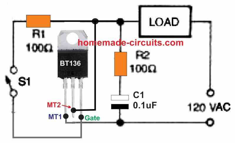
Pull-Down Resistor for SCR/Triac Gates
In SCR or TRIAC triggering circuits like the one shown above, we definitely need a pull-down resistor at the gate side, especially when the gate signal is not coming from a fixed logic level (like a microcontroller) and instead it is coming from push buttons or mechanical switches like S1 and S2 or from a transistor collector.
Why We Need Pull-Down Resistor at the Gate
So in this diagram, the gate is getting signal through a manual setup:
- There is S1 for main power,
- Then S2 which works as a gate pulse switch,
- Then R1 and R2 acting as current limiting resistors.
But look closely, after S2 is released, the gate input becomes floating (open), right?
If there is no proper connection to ground then:
- The gate may still hold some charge,
- It may behave unstable,
- The SCR/triac may trigger wrongly or stay ON or OFF randomly.
So, to keep the gate fully grounded when S2 is open, we add a pull-down resistor. That way, any leakage or stray voltage gets safely drained to ground.
Where and How to Connect Pull-Down Resistor
Just like this bro:
- Connect the one extra resistor from the gate pin to negative line (ground).
- That resistor keeps the gate voltage at zero when no pulse is present.
How to Calculate This Pull-Down Resistor?
Alright now let us come to the main part, how to calculate its value.
This resistor should be:
- High enough so it does not interfere with the main gate triggering current.
- Low enough so it can drain any leftover or leakage current quickly.
So we use this general rule:
Rpull-down = 10 × RgateWhere Rgate is the main gate series resistor which we calculated earlier using the above SCR gate resistor calculator.
Example Calculation
Suppose:
- You already calculated gate resistor Rgate = 180 Ohms.
- Then,
Rpull-down = 10 × 180 = 1800 Ohms or 1.8k OhmYou can use 1.8k or even 2.2k...both are perfectly fine.
Quick Tips
- Pull-down should be at least 5 to 10 times higher than Rgate.
- It should not allow current to bypass the gate signal.
- You can use 1k to 10k Ohms as a safe range in most circuits.
- Always you double-check that pull-down resistor is going to GND not to supply.
Final Words
So now you do not need to scratch your head. Just enter 3 values in the calculator:
- Gate voltage,
- Gate current,
- Your supply voltage...
And instantly you will get the exact gate resistor value that will safely fire your SCR or TRIAC.
If your gate is being triggered by some manual button or mechanical switch or even a transistor collector with open-drain type output, then yes always add a pull-down resistor at gate to keep it stable and prevent false triggering.
And the value is super easy:
Just make it 10 times the gate resistor or simply use 1k to 10k Ohms and you are totally safe.


Questions & Answers
Hi Swagatam,
I want to make a switching device for 220 Vac 2 kw load using BTA41/600 triac, I want triac’s gate to be triggered with same 220 vac.
Can you send me a circuit diagram with component value.
Hi, Rana, I think you can try the second circuit as described in the following article:
https://www.homemade-circuits.com/simple-triac-triggering-circuits-explained/
Thanks, will the values of R1, R2 & C1 remains same for 220 v ac.
I think the R1 value should be changed to 1k, whereas R2 and C1 values can be same as shown in the diagram:
Bonjour de France !
C’est toujours intéressant.
Merci pour la contribution.
JC LM
You are welcome, JC LM!
Namaskar Swatam
I wanted to ask you if in your circuits library you have
1. A circuit for a voltage regulator AC 220V 4000W to control the speed of an induction motor which runs on 220V and draws 1Amp.
2. A charger for NICAD batteries 1.25 Volts which will cut off when fully charged.
Thank you in antecipation
Carlos Peres da Costa
Hi Carlos, you can try any of the circuits from the following article to implement 220V 4kv speed control of an induction motor, but make sure to use a triac rated at 40 amps, so maybe you can use a BTA41/600 triac or similar.
https://www.homemade-circuits.com/simple-ceiling-fan-regulator-circuit/
For Nicad battery auto cut off may not be required if the voltage is constant and current is limited to 10% of its Ah rating.
https://www.homemade-circuits.com/simple-ni-cd-battery-charger-circuit/
Good information. thank you sir.
Thank you Moses, glad you found it useful…