We can use this small LM567 calculator tool for finding the right frequency, Rt, and Ct values for our tone decoder circuit.
Now we know that this IC works on one simple relation which is,
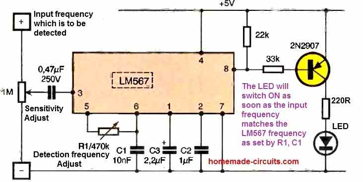
f = 1 / (1.1 × Rt × Ct)
So we can see that this frequency depends only on the resistance and the capacitance connected to pin 5 and pin 6 of the LM567, which is why we can easily calculate one value if we already know the other two. So therefore this online calculator helps us to do that fast without any long calculation.
How the Calculator Works
When we open the calculator then we will see one small box that says “Select what to calculate.” In that dropdown option we can choose what we are trying to find. Suppose if we want to find the Frequency, then we select “Frequency (f)”, if we want to find Rt then we select “Rt”. And if we want to find Ct then we select “Ct.”
Now let us say we selected “Frequency (f)”, then the calculator will show two input boxes, one for Rt (in ohms) and one for Ct (in farads). Here we just need to type our Rt and Ct values and then press the “Calculate” button. It will show the output frequency in hertz instantly.
Now if we select “Rt” instead then we have to enter the frequency (f) and the Ct value and the calculator will give us the correct resistance in ohms.
Similarly if we select “Ct” then we have to enter the frequency (f) and the Rt value and it will give us the capacitance in farads.
We can use decimal numbers or even scientific notation like 0.000001 for microfarad or 1e-6 for 1 microfarad.
Manual Example
Let us now take one small example for understanding.
Suppose we are using Rt = 10000 ohms and Ct = 0.000001 farad (which is same as 1 µF). Then we can put these two values in the calculator after selecting Frequency (f) mode.
So the tool will use this formula:
f = 1 / (1.1 × 10000 × 0.000001)
That becomes f = 1 / 0.011 = 90.9 Hz approximately.
So the output frequency of LM567 will be around 90.9 Hz when Rt = 10 kΩ and Ct = 1 µF.
Now if we want to find what Rt value will give us around 500 Hz using the same Ct = 0.000001 F, then we select “Rt” mode and enter f = 500 and Ct = 0.000001, then the tool will calculate Rt = 1 / (1.1 × 500 × 0.000001) = 1818.18 ohms (approx. 1.8 kΩ).
Same way if we want to find what Ct value will make around 1 kHz when Rt = 10000 ohms then we select “Ct” mode, enter f = 1000 and Rt = 10000. The tool will calculate Ct = 1 / (1.1 × 10000 × 1000) = 9.09 × 10⁻⁸ farad (which is around 0.09 µF).
Using The Tool Practically
So thus we can see that this small calculator makes our design work faster and allows to change Rt and Ct values and check what frequency will match our audio tone or carrier signal. It also allows us to use this LM567 calculator to test which capacitor to choose for a fixed frequency lock range.
But you must always remember that the frequency from the formula is an ideal value, in real hardware experiments it can vary a little because of the tolerance of the resistor and capacitor, so we should always check the final frequency using a frequency counter or oscilloscope when we build the actual LM567 circuit.

Questions & Answers
On the LM567 doesn’t pin 2 cap narrow the bandwidth as it gets larger?
Yes, increasing the value of the capacitor on Pin 2 narrows the detection bandwidth of the LM567 tone decoder.
Thank you
1. What is the largest AC INPUT VOLTAGE TO THE LM567?
2. What caps for max bandwidth would I use at 300Hz?
The absolute maximum AC input voltage is from -10V to 0.5V above your supply voltage. However for the internal tracking loop to work properly and match the datasheet formulas, keep your input signal at or below 200 mV RMS. If your signal is larger, use a resistor divider to step it down.
To get the maximum bandwidth (around 14 percent) at 300Hz with a strong 200 mV RMS input, use a 3.3uF or 4.7uF capacitor on Pin 2 (loop filter). For Pin 1 (output filter), use a 10uF capacitor to prevent output chatter and ensure stable switching.
Thank You!