• Skip to main content
  • Skip to primary sidebar

Homemade Circuit Projects

Need circuit help? Post them in the comments! I've answered over 50,000!

Blog | Categories | About | Hire Me | Contact | Calculators-online
You are here: Home / Notch Filter Calculator Tool

Notch Filter Calculator Tool

This small calculator is made for calculating notch filter frequency using the simple formula f = 1 / 2πR4C4 and as per the given circuit diagram below. We can also use the same calculator in reverse for finding R4 or C4 when the other two values are known to us.
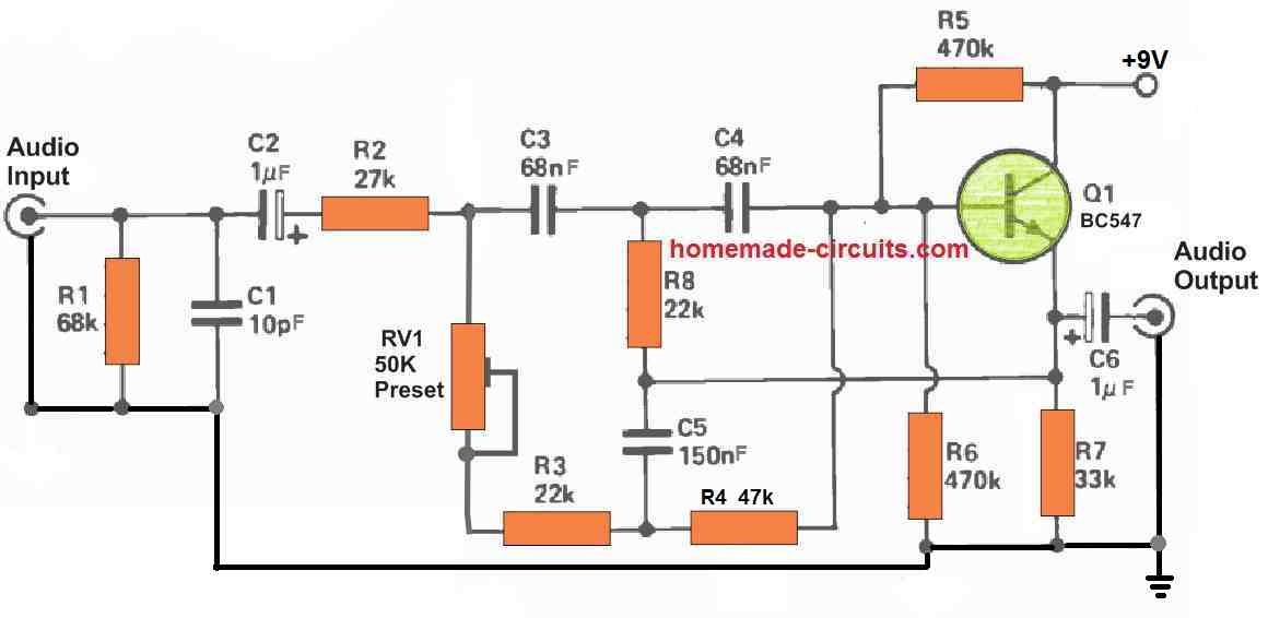
Calculator by homemade-circuits.com

Notch Filter Calculator

Formula: f = 1 / 2π R4 C4
Notes: Enter numeric values only. Units selectable. The calculator uses the plain formula: f = 1 / 2π R4 C4.

We have three radio buttons so that we can select what we want to calculate... f, R4, or C4. When we select one of them, then code automatically hides and shows the proper input boxes according to that mode.

Then we have three main input areas:

  1. R4 input area with its value box and unit dropdown (Ω, kΩ, MΩ).
  2. C4 input area with its value box and unit dropdown (pF, nF, µF, etc).
  3. Frequency input area with its value and unit (Hz, kHz, MHz).

When we select to calculate f, then it hides the frequency input, When we select to calculate R4 or C4, then it shows the frequency box and disables the one that we are going to calculate.

The Buttons Section

Then we see two buttons “Calculate” and “Reset”.
The Calculate button triggers the main math part inside the script.
The Reset button fills back default values for R4 = 10kΩ and C4 = 10nF and clears the result box.

  1. When mode is f:
    Then we take R and C values, then multiply their unit multipliers and calculate frequency using f = 1 / (2 * π * R * C).
    Then it shows both numeric and formatted values on the screen.
  2. When mode is r:
    Then we take f and C values and use the rearranged formula R = 1 / (2 * π * f * C).
    Then the result shows R4 in ohms and formatted value like kΩ or MΩ depending on result range.
  3. When mode is c:
    Then we take f and R values and use the rearranged formula C = 1 / (2 * π * f * R).
    Then the result shows C4 in Farads with formatted readable format like µF or nF.

The code also checks for in-valid or missing values and displays an error message in red if any input is wrong or missing.

Practical Working Calculation

let us now take one clear manual example so that we can see how this notch filter calculator actually works using the formula f = 1 / (2πR4C4).

We will do the full step-by-step math manually just like the calculator would do it.

Example Situation

Let us say we have:
R4 = 10 kΩ
C4 = 10 nF

Now we want to find the notch (center) frequency f.

Step 1 – Convert All Values To Base Units

We must convert both R4 and C4 into ohms and farads first because the formula works only with SI base units.

So
R4 = 10 kΩ = 10 * 1000 = 10,000 Ω
C4 = 10 nF = 10 * 10⁻⁹ = 0.00000001 F

Step 2 – Apply The Formula

The main formula is:

f = 1 / (2 * π * R4 * C4)

Now let us substitute the values:

f = 1 / (2 * 3.1416 * 10000 * 0.00000001)

Step 3 – Do The Multiplications Step By Step

First, multiply R4 × C4:

10000 * 0.00000001 = 0.0001

Now multiply 2 * π * 0.0001:

2 * 3.1416 * 0.0001 = 0.00062832

Step 4 – Take The Reciprocal

Now divide 1 by 0.00062832:

1 / 0.00062832 ≈ 1592.5 Hz

Step 5 – Write The Final Answer

So for R4 = 10 kΩ and C4 = 10 nF,

f ≈ 1.59 kHz

That is the notch frequency.

Step 6 – Verify Reverse Calculation (Optional)

If we now want to find C4 from this frequency and resistance, we can reverse the formula:

C4 = 1 / (2π f R4)

Substitute f = 1592.5 Hz and R4 = 10,000 Ω

C4 = 1 / (2 * 3.1416 * 1592.5 * 10000)
C4 = 1 / 100,000,000 ≈ 1.0 × 10⁻⁸ F = 10 nF

So our math perfectly matches the forward calculation.

Step 7 – Summary Of Example

So in this example,
R4 = 10 kΩ
C4 = 10 nF
Then f = 1 / (2πR4C4) = 1592.5 Hz ≈ 1.6 kHz

That means the notch filter will have its center (cut) frequency at about 1.6 kHz.

Primary Sidebar

My YouTube Channel

Circuit Simulator: Draw and Simulate Schematics

circuit simulator image


Categories

  • Arduino Projects (95)
  • Audio and Amplifier Projects (134)
  • Automation Projects (18)
  • Automobile Electronics (104)
  • Battery Charger Circuits (90)
  • Datasheets and Components (109)
  • Electronics Theory (151)
  • Energy from Magnets and Earth (43)
  • Games and Sports Projects (11)
  • Grid and 3-Phase (20)
  • Health related Projects (27)
  • Home Electrical Circuits (13)
  • Indicator Circuits (16)
  • Inverter Circuits (98)
  • Lamps and Lights (161)
  • Meters and Testers (72)
  • Mini Projects (28)
  • Motor Controller (68)
  • Oscillator Circuits (30)
  • Pets and Pests (15)
  • Power Supply Circuits (91)
  • Remote Control Circuits (50)
  • Security and Alarm (65)
  • Sensors and Detectors (107)
  • SMPS and Converters (46)
  • Solar Controller Circuits (62)
  • Temperature Controllers (44)
  • Timer and Delay Relay (51)
  • Voltage Control and Protection (44)
  • Water Controller (37)
  • Wireless Circuits (31)


Subscribe to get New Circuits in your Email


Other Links

  • Privacy Policy
  • Cookie Policy
  • Disclaimer
  • Copyright
  • Videos
  • Sitemap

People also Search

555 Circuits | 741 Circuits | LM324 Circuits | LM338 Circuits | 4017 Circuits | Ultrasonic Projects | SMPS Projects | Christmas Projects | MOSFETs | Radio Circuits | Laser Circuits | PIR Projects |


Recent Comments

  • Swagatam on Remote Controlled Toy Car using 433 MHz Remote Modules
  • Uchechukwu on Remote Controlled Toy Car using 433 MHz Remote Modules
  • Swagatam on How to Connect IC 4066 in a Circuit
  • Swagatam on How to Check a MOSFET Using a Digital Multimeter
  • Darmco on How to Check a MOSFET Using a Digital Multimeter

Social Profiles

  • Twitter
  • YouTube
  • Instagram
  • Pinterest
  • My Facebook-Page
  • Stack Exchange
  • Linkedin

Calculators

  • ZVS Induction Heater + Tank Calculator Tool
  • Zener Diode Calculator
  • Wire Current and Thickness Calculator (Ampacity Calculator)
  • Voltage Divider Calculator
  • Transistor Base Resistor Calculator
  • Transistor Astable Multivibrator Calculator
  • TL431 Calculator
  • Solar Panel, Inverter, Battery Calculator
  • Ferrite Core Air Gap Calculator Tool
  • Parallel MOSFET Calculator Tool: How to Connect MOSFETs in Parallel Safely
  • LC Resonance Calculator for EV Battery Charger Circuits
  • LED String Series Resistor Calculator
  • PFC (Power Factor Correction) Calculator Tool: 3kW
  • Passive Power Factor Correction (PFC) Calculator
  • LM567 IC Calculator Tool
  • SMPS Flyback Boost Converter Calculator
  • Shunt Resistor Calculator for Ammeters
  • SCR and Triac Gate Resistor Calculator
  • Battery Back up Time Calculator
  • Boost Converter Calculator (Non-Isolated)
  • Bootstrap Capacitor Calculator
  • Buck Converter Calculator
  • Buck-Boost Converter Calculator
  • Capacitance Reactance Calculator
  • DCM Flyback Transformer & Wire Gauge Wire Size Calculator Tool
  • Filter Capacitor Calculator
  • IC 4047 Calculator (Frequency and PWM)
  • IC 4060 Calculator
  • IC 555 Astable Calculator
  • IC 555 Monostable Calculator
  • IC SG3525, SG3524 Calculator
  • Inductance Calculator
  • Induction Heater Inductor and Resonant Frequency Calculator
  • Induction Heater Work Coil Calculator
  • Inverter LC Filter Calculator
  • LC Resonance Calculator
  • LED Current Calculator
  • LM317, LM338, LM396 Calculator
  • NAND/NOT Gate RC Values Calculator
  • NOT, NAND Gate Frequency Calculator
  • Notch Filter Calculator Tool
  • Ohm’s Law Calculator
  • Phase Angle Phase Shift Calculator
  • Power Factor (PF) Calculator
  • RC Filter Calculator
  • Reactance Calculator
  • Sine Table Calculator for SPWM Arduino Code
  • Small Signal Transistor(BJT) and Diode Quick Datasheet
  • SMPS Calculator for Toroidal Ferrite Transformers
  • SMPS Flyback Transformer Calculator – Design by Target Duty Cycle
  • TL431 Calculator
  • Op-Amp Hysteresis Resistor Calculator

© 2026 · Swagatam Innovations