In this post I have explained the making of a simple 3 phase induction motor speed controller circuit, which can be also applied for a single phase induction motor or literally for any type of AC motor.
When it comes to controlling the speed of induction motors, normally matrix converters are employed, involving many complex stages such as LC filters, bi-directional arrays of switches (using IGBTs) etc.
All these are employed for ultimately achieving a chopped AC signal whose duty cycle could be adjusted using a complex microcontroller circuit, finally providing the required motor speed control.
However we can experiment and try to accomplish a 3-phase induction motor speed control through a much simpler concept using the advanced zero crossing detector opto coupler ICs, a power triac and a PWM circuit.
Using Zero Crossing Detector Opto Coupler
Thanks to the MOC series of optocouplers which has made triac control circuits extremely safe and easy to configure, and allow a hassle free PWM integration for the intended controls.
In one of my earlier posts I discussed a simple PWM soft start motor controller circuit which implemented the MOC3063 IC for providing an effective soft start on the connected motor.
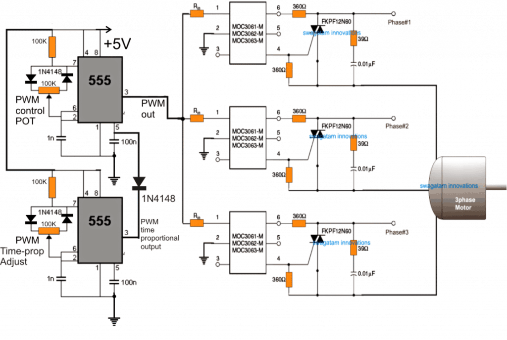
Here too we use an identical method for enforcing the proposed 3 phase induction motor speed controller circuit, the following image shows how this can be done:
In the figure we can see three identical MOC opto coupler stages configured in their standard triac regulator mode, and the input side integrated with a simple IC 555 PWM circuit.
The 3 MOC circuits are configured for handling the 3 phase AC input and delivering the same to the attached induction motor.
The PWM input at the isolated LED control side of the opto determines the chopping ratio of the 3 phase AC input which is being processed by the MOC ICS.
Using IC 555 PWM Controller (Zero Voltage Switching)
That implies, by adjusting the PWM pot associated with the 555 IC one can effectively control the speed of the induction motor.
Output at its pin#3 comes with a varying duty cycle which in turn switches the output triacs accordingly, resulting in either increasing the AC RMS value or decreasing the same.
Increasing the RMS through wider PWMs enables acquiring a higher speed on the motor, while decreasing the AC RMS through narrower PWMs produces an opposite effect, that is it causes the motor to proportionately slow down.
The above features are implemented with a lot of precision and safety since the ICs are assigned with many internal sophisticated features, specifically intended for driving triacs and heavy inductive loads such as inductions motors, solenoids, valves, contactors, solid state relays etc.
The IC also ensures a perfectly isolated operation for the DC stage which allows the user to make the adjustments without the fear of an electric shock.
The principle can be also efficiently used for controlling single phase motor speed, by employing a single MOC IC instead of 3.
The design is actually based on time proportional triac drive theory. The upper IC555 PWM circuit may be adjusted to produce a 50% duty cycle at much higher frequency, while the lower PWM circuit may be used for implementing the speed control operation of the induction motor through the adjustments of the associated pot.
This 555 IC is recommended to have relatively lower frequency than the upper IC 555 circuit. This may be done by increasing the pin#6/2 capacitor to around 100nF.
Assumed Waveform and Phase Control using the above Concept:
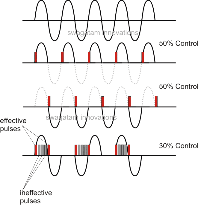
The above explained method of controlling a 3-phase induction motor is actually quite crude since it has no V/Hz control.
It simply employs switching the mains ON/OFF at different rates to produce an average power to the motor and control the speed by altering this average AC to the motor.
Imagine if you switch the motor ON/OFF manually 40 times or 50 times per minute. That would result in your motor slowing down to some relative average value, yet moving continuously. The above principle works in the same way.
A more technical approach is to design a circuit which ensures a proper control of the V/Hz ratio and automatically adjusts the same depending on the speed of the slip or any voltage fluctuations.
For this we basically employ the following stages:
- H-Bridge or Full Bridge IGBT driver Circuit
- 3-Phase Generator Stage for Feeding the Full Bridge Circuit
- V/Hz PWM Processor
Using a Full Bridge IGBT control Circuit
If the setting up procedures of the above triac based design look daunting to you, the following full-bridge PWM based induction motor speed control could be tried:
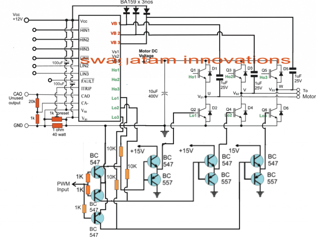
The circuit shown in the above figure utilizes a single chip full-bridge driver IC IRS2330 (latest version is 6EDL04I06NT) which has all the features in-built in order to satisfy a safe and a perfect 3 phase motor operation.
The IC only needs a synchronized 3 phase logic input across its HIN/LIN pinouts for generating the required 3 phase oscillating output, which finally is used for operating the full bridge IGBT network and the connected 3 phase motor.
The speed control PWM injection is implemented through 3 separate half bridge NPN/PNP drivers stages, controlled with a SPWM feed from an IC 555 PWM generator as seen in our previous designs. This PWM level may be ultimately used for controlling the speed of the induction motor.
Before I have explained the actual speed control method for the induction motor, let's first understand how the automatic V/Hz control can be achieved using a few IC 555 circuits, as discussed below
The Automatic V/Hz PWM Processor Circuit (Closed Loop)
In the above sections I have explained the designs which will help the induction motor to move at the rate which is specified by the manufacturer, but it won't adjust according to a constant V/Hz ratio unless the following PWM processor is integrated with the H-Bridge PWM input feed.
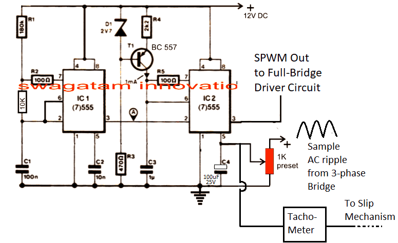
The above circuit is a simple PWM generator using a couple of IC 555. The IC1 generates the PWM frequency which is converted into triangle waves at pin#6 of IC2 with the help of R4/C3.
These triangle waves are compared with the sinewave ripple at pin#5 of IC2. These sample ripples are acquired by rectifying the 3 phase AC mains into a 12V AC ripple and is fed to pin#5 of the IC2 for the required processing.
By comparing the two waveform, an appropriately dimensioned SPWM is generated at pin#3 of IC2, which becomes the driving PWM for the H-bridge network.
How the V/Hz Circuit Works
When power is switched ON the capacitor at pin#5 begins by rendering a zero voltage at pin#5 which causes the lowest SPWM value to the H-bridge circuit, which in turn enables the induction motor to start with a slow gradual soft start.
As this capacitor charges, the potential at pin#5 rises which proportionately raises the SPWM and enables the motor to gain speed gradually.
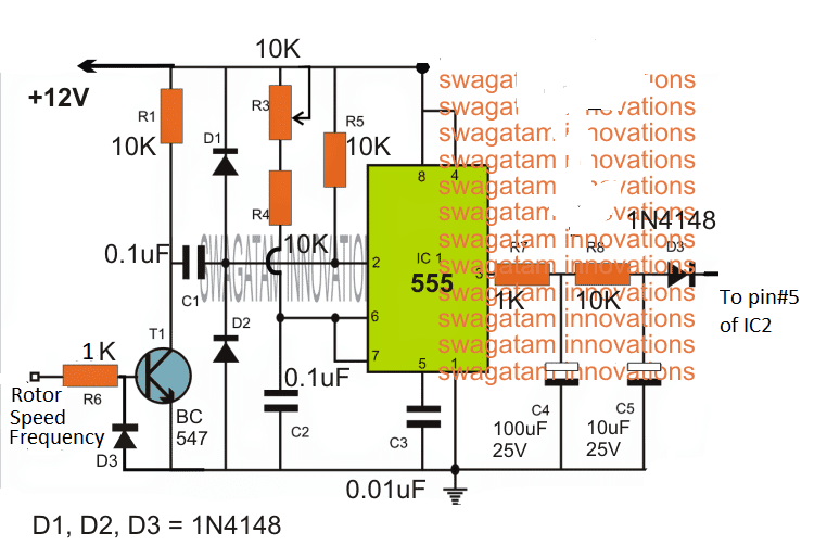
We can also see a tachometer feedback circuit which is also integrated with pin#5 of the IC2.
This tachometer monitors the rotor speed or the slip speed and generates additional voltage at pin#5 of IC2.
Now as the motor speed increases the slip speed tries to synchronize with the stator frequency and in the process it begins gaining speed.
This increase in the induction slip increases the tachometer voltage proportionately which in turn causes IC2 to increase the SPWM output and this in turn further increases the motor speed.
The above adjustment tries to maintain the V/Hz ratio to a fairly constant level until finally when the SPWM from IC2 is unable to increase any further.
At this point the slip speed and the stator speed acquire a steady-state and this is maintained until the input voltage or the slip speed (due to load) are not altered. In case these are altered the V/Hz processor circuit again comes into action and begins adjusting the ratio for maintaining the optimal response of the induction motor speed.
The tachometer
The Tachometer circuit can be also cheaply built using the following simple circuit and integrated with the above explained circuit stages:
How to Implement the Speed Control
In the above paragraphs we understood the automatic regulation process that can eb achieved by integrating a tachometer feedback to a auto regulating SPWM controller circuit.
Now I have explained how the speed of an induction motor can be controlled by varying the frequency, which will ultimately force the SPWM to drop and maintain the correct V/Hz ratio.
The following diagram explains the speed control stage:
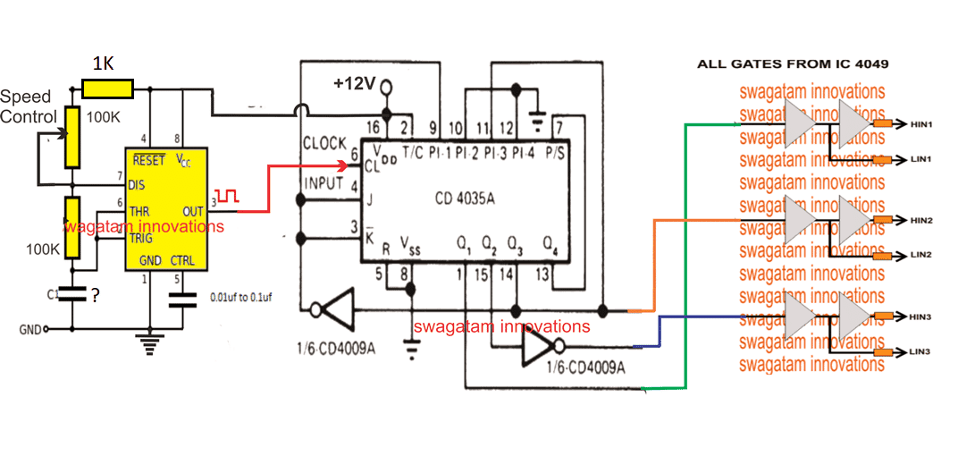
Here we can see a 3-phase generator circuit using IC 4035 whose phase shift frequency can be varied by varying the clock input at its pin#6.
The 3 phase signals are applied across the 4049 IC gates for producing the required HIN, LIN feeds for the full -bridge driver network.
This implies that by suitably varying the clock frequency of IC 4035, we can effectively change the operating 3-phase frequency of the induction motor.
This is implemented through a simple IC 555 astable circuit which feeds an adjustable frequency at pin#6 of IC 4035, and allows the frequency to be adjusted through the attached 100K pot.
The capacitor C needs to be calculated such that the adjustable frequency range comes within the correct specification of the connected induction motor.
When the frequency pot is varied, the effective frequency of the induction motor also changes, which correspondingly changes the speed of the motor.
For example when the frequency is reduced, causes the motor speed to reduce, which in turn causes the tachometer output to reduce the voltage proportionately.
This proportionate reduction in the tachometer output forces the SPWM to narrow down and thereby pulls down the voltage output to the motor proportionately.
This action in turn ensures that the V/Hz ratio is maintained while controlling the induction motor speed through frequency control.
Warning: The above concept is designed on theoretical assumptions only, please proceed with caution.
If you have any further doubts regarding this 3-phase induction motor speed controller design, you are most welcome to post the same through your comments.



Questions & Answers
Will this circuit replace vfd
VFD purpose is different than the above, VFD is for matching motor frequency specs correctly with the input mains frequency…whereas the above is for specifically adjusting speed.
you can use 1K for it, calculation is not necessary
Dear brother what will be transister we want to use? Also can i use 1n4007 for the doide bridge?
Dear Siva, the diode should be rated much above the motor current specs.
the transistor is supposed to be a suitably rated IGBT
Hi Swag.
Greats works. Your site is a real reference for many persons.
I failed realising 10A / 220 v dc for a motor a found but I am still trying reading more and more articles on your site to increase my chances.
When I have something working I'll feed back
Thanks
Thanks Michel, but I cannot see any 220V 10 amp DC figure in the above article?
Dear is it working with soft start?
Dear Sir,
Let me know pwm static voltage regulator with buck boost transformer. If have simple schematic without PIC, share some idea. I appreciate much for soon reply.
Your Sincerely,
KL
Dear KYI,
you can refer to the following article
https://www.homemade-circuits.com/2013/06/universal-ic-555-buck-boost-circuit.html
Hi Swagat,
Is there any IC with 3 PWM pins which can directly generate a sine wave using PWM to drive, say, a MOSFET or something? I was searching for something simple for a project. Please could you point me in the right direction?
Thanks in advance
Hi George, there's no such IC in my knowledge which can do such thing.
you can manufacture SPWM by feeding a fast triangle wave and a slow triangle wave across the two inputs of any opamp…the output from the opamp could be applied to the mosfets for the required sinewave AC generation.
Sir,
Thanks for your reply and i am waiting eagerly for your post.
I have published it here
https://www.homemade-circuits.com/2016/11/submersible-pumpset-timer-circuit.html
Sir pwm put its ok but not working in put voltage 90-90-90
Raj, I have clarified at the bottom of the article that the design has problems
possibly I will try to update a corrected version of the same soon…
Sir update version use 4 doide 1n4007 and what's transistor no……..
bta12 use for fkpf12n60
please ignore the last diagram, the first diagram can be used with some modification, will try to update the design soon…
Sir
In PWM circuit, can you post a Microcontroller circuit(AT89c2051) instead of NE555 circuit
If possible I'll try to update it soon…
THANKS N WAITING
Dear Sir
Your blog is really great! I am beginning to learn electronics now!
I have a Desiel car engine and would like to couple the same with a 5-7KvA 3 phase Alternator for my home use. Would you be kind enough to kindly provide a Governor Circuit design for the same ? (either electronic or electromechanical)? I assure you that I would try out the same and update your blog, hopefully in the interest of all you interested fans!
Thank you very much in anticipation.
Kind regards
Imsa Naga
thanks imsa, please elaborate on the specifications of the "governor" design so that I can understand what exactly you are looking for?? do you mean a speed controller??
Yes, Precisely an Engine Speed Controller. Thank you for the prompt reply !
OK then may be you can try the following concept
https://www.homemade-circuits.com/2016/12/diesel-generator-rpm-controller-circuit.html
Thank you very much indeed. Will be Looking forward your design.
Kind regards
Imsa Naga
thank you for your patience!!
Dear Sir, Could you spare some time for the above mentioned "ELECTRONIC ENGINE SPEED GOVERNOR" design?
thanks again.
Imsa Naga
Dar Imsa, I have posted it here:
https://www.homemade-circuits.com/2017/01/electronic-engine-speed-governor-circuit.html
Sir,
I tried the 3Ph_Ind mot circuit,Its working with AC motor.
And I connected a 100w Bulb on out put as single phase its doesn't dimming but,
fluctuating in the slow speed. help me to solve the problem
thanks
Ajit
Ajit, sorry I could not get it…which circuit are you referring to??
SIR,
I Told about 3 phase induction motor speed controller .
the one which is explained in the above article?…the last one?
The Last updated additional 555 pwm circuit which I have tried
but output fluctuating when decrease the speed. On full speed its working well.
is it happening for the bulb or for the motor?
anyway you can try adjusting the frequency of the lower iC555 by increasing its capacitor and see how it works.
I tried motor and bulb.I will check the capacitors then after reply to you
great swagatam sir.
OK thanks
Sir,
I increased the capacitor value up to 1uf. but could not get a good result.
here speed reducing no doubt but only blinking (bulb) or jerking (motor) in slow speed.if possible please post a microcontroller based circuit instead of 555.
thanks once again
Ajitkumar
Ajitkumar, the above presented concept in the last diagram is perfect, but the circuit will need to be adjusted with proper understanding and with with some experimentation, by using an oscilloscope.
the 1uF was just a suggestion, it's not the exact value.
I think Triac does not support to pwm speed controller for induction motor. only possible to on and off the output ?
using the last time proportional theory, the AC 50Hz cycles is broken into pieces using PWM and the gap between these breaks decides the speed on the motor. higher gaps causes the motor to slow and lower gaps increases the speed.
I think the problem could be in the use a common signal for all the 3 phases, the PWMs needs to be synchronized with the 3 phase cycles separately so that the splitting of the AC is done uniformly across the 3 phases.
In short the PWMs should be also released in accordance with the 120 degree phase shifts
A much easier and better idea would be to use a mosfet or IGBT based full bridge driver which I will upadte soon here.
Dear sir I tried this circuit as single phase also and referred MOC3061 series is a zero crossing opto-triac it gets ON only at the zero cross of the mains even if the excitation pulse comes sooner so it cannot control the firing angle that is needed to speed control. any other random firing optotriac may be possible.any way waiting to a openloop 3@ motor controller.
Ajitkumar, the zero crossing will not have much impact if the frequency of the upper 555 IC is set to a reasonably high level. Because if the frequency is high one of the pulse will be able to somehow catch hold of the zero crossing start point and trigger the triac,
The zero crossing basically helps to reduce RF interference to the minimum.
having said this it would also interesting to see how a non-zero-crossing opto coupler responds with this circuit
I'll try to update the mosfet version soon next week…if i forget please do remind me.
WE ARE WAITING FOR NEW UPDATION OF TREE PHASE MOTOR CONTROLLER
I will update it tomorrow, in the meantime you can refer to the following article, I am going to apply and modify this concept…
https://www.homemade-circuits.com/2014/12/simple-3-phase-brushless-bldc-motor.html
I have updated the full bridge design….you may check it out
But,how will on the high side mosfets?
is it connect to direct on Ho1-Ho3 of IRS chip ?
yes, The gates are marked Ho1, Ho2, Ho3, meaning these will connect with the IC pinouts which are also identically marked
sir
The old post triac based motor speed control, if we avoid the pwm control section and power circuit use for just on and off for a low voltage three phase induction motor (100 volt to 150 volt) frequently with help of a on off sensor,in 100 or more voltage,motor too hot after some time running.if apply 50v three phase it will be working fine.but in 50 volt it does not work with full speed.can you give any suggestion. and can you post a relay tripping circuit if the motor over heated or mechanically jam.
thanks
Ajitkumar