In this post I have explained a circuit idea which can be used as a power monitor and control system for ensuring that only the specified amount of watts is allowed to enter into the allocated socket, as per the maximum calculated wattage of the appliances connected across those points. The idea was requested by Mr. Bob Rudman.
Technical Specifications
I have solar panels on my roof that pump 3Kw into the grid in full sunlight, I don’t get the money for what goes’ into the grid, my landlord does, I only get the savings for the energy I use during the hours of daylight.
What I want is a circuit to automatically adjust the power fed into my water heater or night storage heater that would be plugged into a wall socket to match that coming from the solar panels.
The way this would work would be to monitor the energy going into the grid on the mains cable coming into the house, and automatically adjust the power going into the appliance to bring this to a null point I.E. ( nothing coming in and nothing going out ).
I used to have one of those energy monitors that showed how much energy I was using, but I had to stop using it after the solar panels were fitted as it was unable to detect which way the current on the mains was flowing, so this is something which will need to be considered in the design of the circuit.
Hope you can help.
Best regards Bob Rudman
The Design
As far as I have understood, the application requires a system to monitor and allow a specified amount energy to enter the grid which may be equivalent to the intended load wattage rating in use.
The idea actually may be technically incorrect, and might not be feasible, because once the specified solar inverter energy is fed into the grid line, it becomes accessible to all who may be connected with the grid across the area.
However, if the solar AC is fed to the grid line that may be close to the intended appliances then it might be possible to some extent to optimize the energy as per the load specs.
The other loads at distant levels might not be able to access the power due to relatively higher resistance of the wire offered on the path.
The following diagram explains how the concept may possibly be implemented:
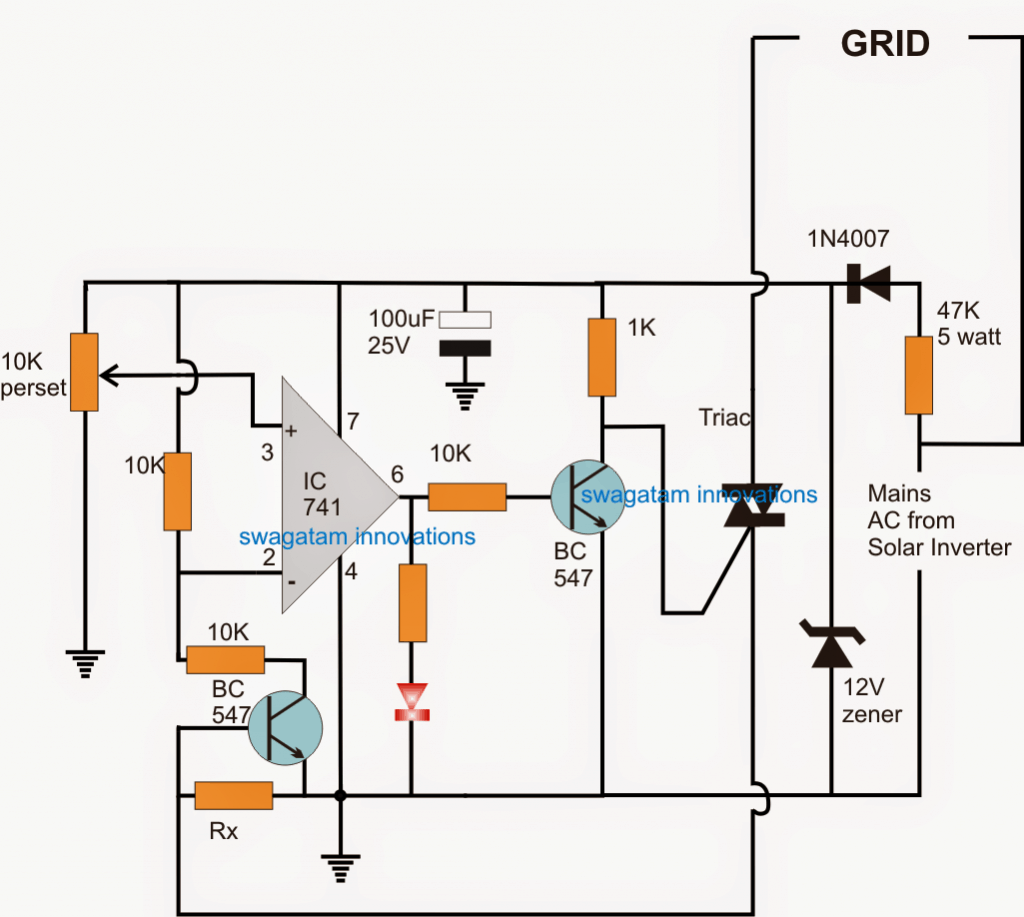
Circuit Operation
The idea looks pretty simple now, here the opamp is configured as a comparator.
Initially the triac MT1/MT2 points are shorted temporarily and the input power from solar inverter is switched ON.
The specified range of load is connected right across the grid points where this AC is applied.
The above action develops a certain predetermined level of potential across Rx which becomes just sufficient for triggering the associated BC547 transistor.
The transistor grounds the pin#2 of the IC via the 10K resistor producing a certain level of potential difference at pin#2.
After this, the pin#3 preset is adjusted so that the red LED just lights up, which indicates pin#6 is rendered high and the connected BC547 is now switched ON.
This in turn makes sure that at this point the triac is switched OFF, however it does effect the situation since we have the triac points shorted and the circuit is in the setting up phase.
The procedures sets up the circuit so that now the power is switched OFF and the short across the triac is removed.
The circuit is now fully set for responding and cutting OFF the triac as soon as the connected load wattage exceeds the specified limit, the triac is forced to switch off which in turn switches of the load (for a fraction of a second) until the situation is corrected across the opamp input pins enabling the triac to switch ON again, and the situation keeps switching at a rapid rate making sure that the grid is supplied only the predetermined fixed amount of power as set by the user.
Rx may be set as per the following formula:
Rx = 0.6/max intended grid wattage
The triac current rating may be selected as per the load wattage specifications.


Questions & Answers
Hello Swagatam, I am trouble shooting a scope inverter module on a IFR FM/AM 1100S radio test set. I was monitoring over the air signals on the combination oscilloscope and spectrum analyzer when a burning smell started and the scope waveform distorted. After unplugging the test set, I removed the cover and discovered a blown tantalum capacitor C11 150uf 15V that filters the 12vdc and a burned resistor R2 68ohm 1/4 watt that is on the emitter of Q1 transistor MPS-A13 which is a start up circuit. After replacing both parts it happened again after turning on the scope, I immediately turned off the scope and unplugged the set. After removing the blown capacitor I monitored the 12vdc feed for the inverter module (4000 scope inverter), 12vdc feed tested ok. I took Q1,C10 and C2 out of circuit and they tested ok. What do you think I should look for next?
Thanks, Paul (I was not able to paste the schematic)
Hello Paul, did you replace the 150uF capacitor with a 25 V or higher rated capacitor? A capacitor will normally burn only when the input voltage exceeds its printed voltage value?
However, If the emitter resistor is burning that means the transistor might be shorted. Please check if there’s also a resistor in series with the collector? If you have a resistor at the collector and base of the transistor then the emitter resistor can never burn.
Connect a 12V bulb in series with the supply positive and check its ersponse, if it burns brightly then something in the circuit might have been shorted, try to trace it out
Hello Swagatam,
I replaced the capacitor with a 16v, I’ll look for a higher voltage. No resistor in series with collector for Q1. Q1 junctions tested ok out of circuit, Q2 and Q3 are sje1461 transistors connected to the transformer. I was going to check them also.
Thanks for the help,
Paul (schematic sent in email)
Hello Paul, try a capacitor rated at 25 V which will ensure guaranteed safety for the capacitor. Sorry I did not find any email from you.
Hello Swagatam,
I sent the email with the schematic to.
wordpress@162.240.8.81
Not able to attach to the reply.
I’ll get a 25v capacitor for replacement and look for any short circuit. If you get the schematic let me know. Thanks, Paul
Hello Paul, would it be possible for you to share the link through Google drive link? I may then look into it.