In this post I have explained 2 simple concepts for making solid-state triac based Inverter/mains AC changeover circuit, the idea was requested by Music girl.
Technical Specifications
I would like to replace the SPDT relay with 2 scr's. Would you consider a circuit to replace those changeover relays?
I believe a relay would need to handle 60 amps to be effective for the inverter side... and a smaller SCR for the Charger side.
Many thanks for the great work you do
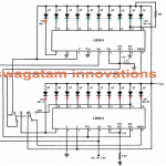
The Design #1
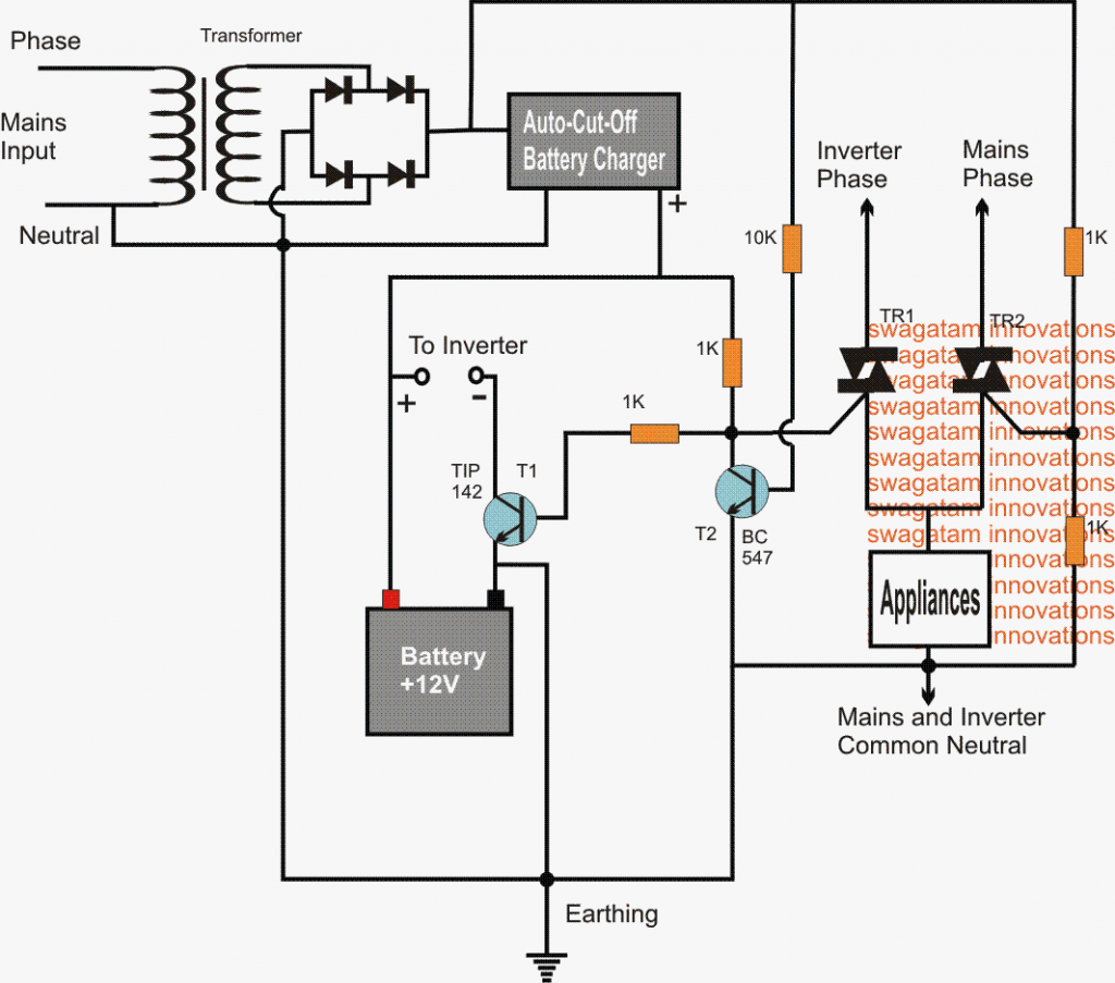
The functioning of the above shown triac based solid state inverter mains changeover circuit may be understood with the help of the following points:
Assuming mains grid AC to be present:
1) The battery charger section is in the active state and charging the battery.
2) The DC from the charger supply keeps T2 and the triac TR2 switched ON.
3) TR2 allows the load to get the mains supply voltage from the mains AC source.
4) T2 keeps triac TR1 and T1 switched OFF, disabling the battery supply to the inverter and cutting-off the mains entry from the inverter to the load respectively.
5) In an event when mains AC fails, T2 and TR2 switch OFF giving rise to the following conditions.
6) T1 connects the negative of the battery with the inverter circuit, quickly switching it ON.
7) TR1 makes sure that AC generated by the inverter is instantly allowed to pass to the appliances ensuring an uninterrupted changeover from the AC mains to the inverter mains through the relevant switching of the triacs.
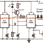
Design #2: Automatic Triac Changeover Circuit for Inverter/Mains
The second circuit below discusses a simple automatic triac changeover circuit from mains to inverter and vice versa for ensuring a well isolated inverter mains transfer for the load. This is to eliminate the possibility of the grid energy meter recording the inverter supply consumption in the utility bill. The idea was requested by Mr. Puneet
Circuit Objectives and Requirements
- Its great pleasure to get guided by you. Thank you so much.
- I was looking out for SPDT/DPDT SSR required to work 24*7 with minimal power/heat.
- My residence is basically divided into two sections which are powered by two different 230v AC phases. Lets name them P1 and P2.
- Now, the problem starts when a power inverter comes into picture. The inverter is powered by P1 but powers some electricals in other section which is basically powered by P2.
With new energy meters, which basically calculate the consumption based on difference between incoming phase and outgoing neutral currents, do calculate the load on both energy meters. - I thought of putting a SSR based phase selector (not mechanical one due to wear and tear on 230v AC load).
- The SPDT NC would would connect invertor, whereas NO would connect load to P2. P2 would power the trigger i.e. operate the relay.
- So when P2 is available, it would ON the relay and NO would connect powering load with P2, whereas in absence of P2 would switch off relay connecting invertor line to section load.
- I am finding it difficult to find some SPDT/DPDT SSR which fulfill my requirement or if any are very costly, so if you can help me with any such circuit.
Assessing the Circuit
Thanks Puneet, basically you want a solid-state SPDT changeover relay which will switch the load from mains to inverter during mains failure and vice-versa when mains returns....this will also prohibit the energy meter from registering the inverter current in its calculation while inverter is running.
I hope I have understood it rightly??
This would also require isolating the neutral so that the energy meter is completely disconnected from the load and the neutral line during mains absence.
Isolating the Neutral
That's perfectly right!
I would beg to differ on the last point - isolation of neutral on mains absence. The reason being the live wire from invertor is directly connecting in section2 and not from energy meter. Since mains is off, i believe the energy meter circuit may not be powered to sense the consumption on neutral side.
I may be wrong in my assumption. So if you feel neutral also needs isolation, please design the circuit accordingly. That was some confusion i had, thus i always mentioned SPDT/DPDT in my request.
Let me know if any more information required.
Thank you 🙂
Puneet
Solution:
I think DPDT could be slightly more complex with a triac based relay, so it's better to stick with an SPDT variant.
I think you could give the last SPDT circuit in the above article a try, with some modifications.
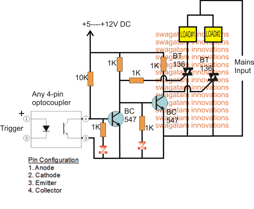
Here you can join the lower leads of the triac together and connect with the load (the other end of the load connected with the neutral), while the upper leads could be separated and joined with the respective phases (mains, and inverter)
for supplying the circuit under both the situations we could use two 0.33uF separately, one connected with the mains, and the other with the inverter phase.
Just for my clear understanding, I am confused with the last statement about 0.33uf capacitors, where exactly should I put them across?
Few queries:
1. do I need to add heat sinks to the triacs? 2. I believe the trigger is 5v dc sourced from mains. Should I go for transformer supply to drop 230v ac to 5/6v ac and rectify? If you have any specific design for that please guide me. 3. If not dc in above, do I need to take special care for zero crossing for the optocoupler.
I had redrawn the circuit diagram as per your instructions, but could not upload it here.
Hi Puneet, you can send the diagram to my email
the trigger can be 5V or 12V that is not critical.
In the last diagram, the 0.33uF can be see connected with the mains, you can connect a second 0.33uF from the zener side and connect its other end with the inverter mains...this would enable the transistor circuit to operate in both the situations, during absence and presence of mains.
Zero crossing triggering is not required according to me.
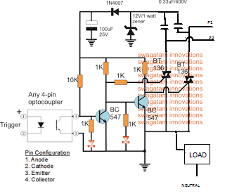
Modified Triac Changeover Design
Hello Swagatam,
Please find attached the modified circuit diagram. I hope i have modified it as per your instructions. Let me know your valuable feedback.
I would also request you to suggest the best possible option to get the 5v DC signal at trigger end. should i look out for transformer-less supply or transformer one.
With respect to the 0.33uF capacitors, i doubt if i have made the right connection or should this be coming from the lower ends of the triacs, as here the two phase inputs would collide.
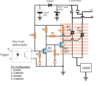
Corrections
Hello Puneet,
the 0.33uF connections are OK, the current on the other side of 0.33uF will be quite low and won't harm each other.
the lower side of the triacs are supposed to be connected only with the load not with the circuit negative, the negative of the circuit should be connected directly with the neutral. rest all looks OK.
Thank you so much for your quick reply.
I hope this one is correct. My bad luck i did not see the phases being shorted to ground/neutral at lower triac ends 🙁
Would this circuit be capable for handling around 500 watts of load?
Hello Puneet,
Now it looks OK, and hopefully should function as per the expectations.
The trigger to the opto could be extracted from either of the mains supply, that is either from the inverter mains or the grid mains, depending on which one is selected for the activating the triac changeover circuit.
The input of the opto could be connected with these supplies through a 68K 5 watt resistor.

Questions & Answers
hello swagatam I remember one or two years ago ago you shared a diagram with me and you said it was better than a ups , actually it was all about automatic turn on/off for the inverter and I think it was using relay, for example if you are watching TV and power goes off it will automatically turn on the inverter, when power comes back it will automatically turn off the inverter
Hi Rashid, Yes I remember, it was the following design which I had referred to you:
https://www.homemade-circuits.com/how-to-convert-inverter-to-ups/
However, there will be a slight delay of a few milliseconds between the changeover from inverter to Mains, and vice versa.
Thanks for this great job, but is only one circuit i.e first circuit diagram
Thank you Ismaila.
Thanks for the circuit, but …
The traic doesn’t turn off until the AC voltage it gets goes to zero.
For the case where the AC comes back on, the worst case is the generator could be at +120v while the line is at -120! So very high current flow buring out the traics and maybe the generator.
So the line connected to the generator voltage needs to cross to zero (but not turn it on for the other half for the sine wave) before turning on the line traic.
Hi Swagatam,
Hope you are doing fine. This article is quite informative. Has anyone tried this circuit? I want to switch a load of around 3KW from one source to other. I understand that BT136 may not be able to handle that. BTA41 would be a better choice. Having said that, do we need to have any other protection to switch that high load? What about snubber circuit? In fact, I created similar circuit (I had two optoisolators to drive BTA41 separately). It worked fine (I observed some flickering on the load side though) but BTA41 blew off after around 10 days. One reason could be thermal mismanagement. I used very small heatsink with no air cooling. I would like to discuss this in detail if you are available.
Best,
Suresh
Hi Suresh, I am not sure whether it was confirmed perfectly by anybody or not, but according to me the concept looks flawless, especially the second last one.
If the load is inductive then definitely a snubber network will be required. You can probably design it by referring it to the following link:
https://www.st.com/resource/en/application_note/cd00004096-rc-snubber-circuit-design-for-triacs-stmicroelectronics.pdf
I also found that 20 Amp snubberless triacs are available that have in built snubbers.
If you have any further questions we can discuss it here.
Thanks Swagatam for prompt reply. Yes, conceptually it should work. My circuit also worked fine for few days but seems there was some issue with thermal management or spike management. Also, I think it is last circuit in above article which is worth trying. The second last has issue with connection of load.
Best,
Suresh
You are right Suresh, the last circuit actually looks more appropriate and worth trying. Also, a large heatsink is a must for any triac if it is switching heavy loads
Hello Swagtam.
Great finding you after I lost your follow_up.
I’m concerned over the above Auto changeover cct.
I do inverter and mostly, customers require them automated.
I’ve been doing a relay set up but in most of my projects, delay of changing Over is the problem.
For my usual set up, I use two relays.
1, for switching between line AC and inverter. And the second, usually small, for switching off the inverter oscillator.
My question is how can I solve the delay in relay transfer.
Then I would be glad if the above Relay_less changeover would be fully composed of all parts. I mean you show all its set up accessories.
Thank you for your continued support sir.
Thank you Peter,
Relays normally have fixed operating specifications depending on their coil resistance and spring tension. Although the activation time can be made faster by using slightly higher operating voltage than the specified value, the release time cannot be made faster.
According to me, relays with low coil resistance require higher current to operate, and therefore these may have faster activation time, and identically they may have faster release time also due to a stronger spring tension. You can use one of these relays having 3 sets of contacts, two for the AC mains changeover and one for the oscillator cut off.
PLEASE SIR! I NEED AUTOMATIC PHASE SELECTOR CIRCUIT DIAGRAM WITH MICROCONTROLLER AND HOW TO SET IT UP
Hello Swagatam sir,
I am from Nepal I am following you & your wesite from last so many years.I am very impressed by your helping nature & your creative work.
could you pls. help me for a small circuit ?
I want to switch off SMPS power supply until the solar battery runs out or when the sun is shining during the day. I was using a relay but it is interrupting to start wifi by .2 sec
So now I want to use Triac switch (Normally closed) type with using a optocoupler.
could you pls. guide me how to make Triac Normally closed? (NC)
Thank you Mohan or being a part of this website for so many years, I appreciate it very much!
I think the following circuit might help you to achieve the required implementation. You can customize it further to suit your specific needs!
https://www.homemade-circuits.com/12v-dc-solid-state-relay-ssr-100-amps/
Ok but what of the P1 and P2 stand for?
And what is the remain 2 pin of outcoupler 1+ and 2 ?
GOOD MORNING SIR,
PLEASE SIR WHICH ONE IS THE BEST AMONG THOSE CIRCUITS BECAUSE I WANT TO MAKE IT TODAY FOR MY INVERTER
Bashir, you can try the last circuit
should i make all resistors 1watt or 1/2watt?
all are 1/4 watt
hello swagatam, what are the watts of those resistors? about the triac' pins, pin1 is A1-down vertical one. pin2 is A2-upper vertical one. pin3 is G-bended one. am i right? i used BTA41 but one to inverter phase and BC547 got damaged. should i use BT136?
hello afam, with printed side of the triac facing you, the right most lead corresponds to the bent lead, the center lead corresponds to the appliance lead, and the left most lead goes to the mains. The BTA41 is more powerful than BT136 so if it blew then BT136 will also get burnt
make sure you do it by understanding the everything correctly and convincingly.
honestly i love the way u explain things that is why i come here to seek solution. i will try this circuit later bcos i love it.
thank you Afam, I appreciate your thoughts,
for adjusting the frequency you will probably require a VFD circuit as given below:
https://www.homemade-circuits.com/2013/09/single-phase-variable-frequency-drive.html
however this circuit could be quite complex and will require an advanced knowledge regarding the subject.
please i wish to make a request. my genset output is 220v 35Hz. is there any circuit that will correct the output to 220v 50Hz. thanks