In this post I have explained an effective PWM motor soft start circuit which can be used for enabling heavy motors with a soft start and thus prevent the equipment from drawing dangerous high currents.
Why a Soft Start
High wattage motors such pump motors or other forms of heavy industrial motors tend to draw huge current during their initial power switch ON, which in turn impacts the associated fuses and switches adversely causing these to either blow of or degrade overtime. In order to remedy the situation a soft start circuit becomes highly imperative.
In a few of my previous articles I have explained regarding a related topic, which you may learn comprehensively through the following posts:
Soft start circuit for pump motors
Soft start circuit for refrigerators
Although the above designs are quite useful, these may be considered slightly low tech with their approach.
In this article we'll see how the process may be implemented using a much sophisticated PWM based motor soft start controller circuit.
Using PWM Concept
The idea here is to apply a gradually incrementing PWM to a motor each time it's switched ON, this action allows the motor to attain a linearly increasing speed from zero to maximum within a stipulated period of time, which may be adjustable.
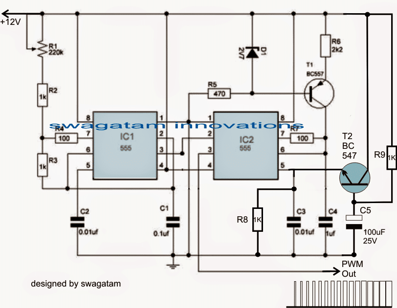
Note: Please use a Darlington BC547 configuration at pin#5 of IC2 instead of a single BC547. This will produce a more effective response compared to a single BC547
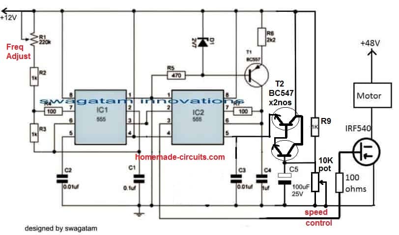
Example circuit for a variable 48V motor controller with soft start
How it Works
Referring to the figure above, the production of the linearly incrementing PWM is achieved with the help of two 555 IC, configured in their standard PWM mode.
I have already discussed the concept elaborately in one of my earlier articles explaining how to use IC 555 for generating PWM.
As may be witnessed in the diagram, the configuration employs two 555 ICs, IC1 being wired like as astable, while IC2 as a comparator.
IC1 generates the required clock signals at a given frequency (determined by the values of R1 and C2) which is applied to pin#2 of the IC2.
IC2 utilizes the clock signal to generate triangle waves across its pin#7, so that these may be compared with the potential available at its control voltage pin#5.
Pin#5 acquires the required control voltage via an NPN emitter follower stage made with the help of T2 and the associated components.
When power is switched ON, T2 is fed with a ramping or a gradually increasing voltage at its base via R9, and due to the proportionate charging of C5.
This ramping potential is appropriately duplicated across the emitter of T2 with respect to the supply voltage at its collector, meaning the base data is converted into a gradually increasing potential ranging from zero to almost the supply voltage level.
This ramping voltage at pin#5 of IC 2 is instantly compared with available triangle wave across pin#7 of IC2, which is translated into a linearly incrementing PWM at pin#3 of IC2.
The linearly incrementing process of the PWMs goes on until C5 is fully charged and the base of T2 attains a stable voltage level.
The above design takes care of the PWM generation each time power is switched ON.
Video Clip:
The following video shows a practical test result of the above PWM circuit implemented on a 24V DC motor. The video shows the PWM pot adjustment response of the circuit on the motor, and also an additional battery indicator LED response while the motor is switched ON and OFF.
Integrating a zero Crossing Triac Controller
In order to implement the PWM motor soft start circuit effect, the output from pin#3 of IC2 is required to be applied to a triac power driver circuit, as shown below:
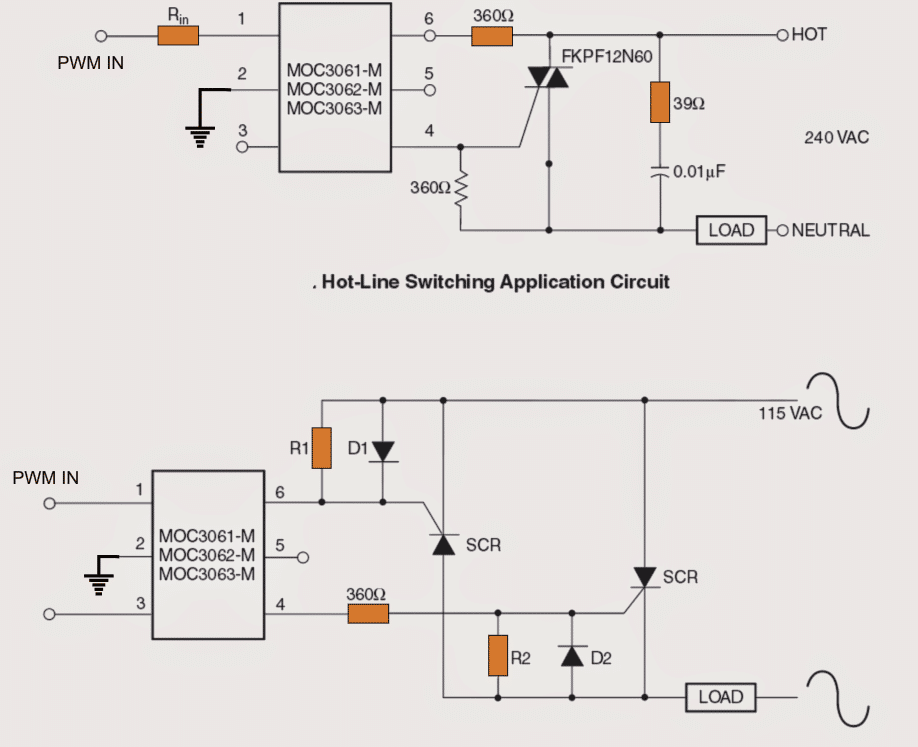
The above image shows how the switch ON soft start PWM control may be implemented on heavy motors for the intended purpose.
In the image above we see how triac driver isolators with zero crossing detector can be employed for driving the motors with the linearly incrementing PWMs for executing a soft start effect.
The above concept effectively takes care of the start ON overcurrent situating on single phase motors.
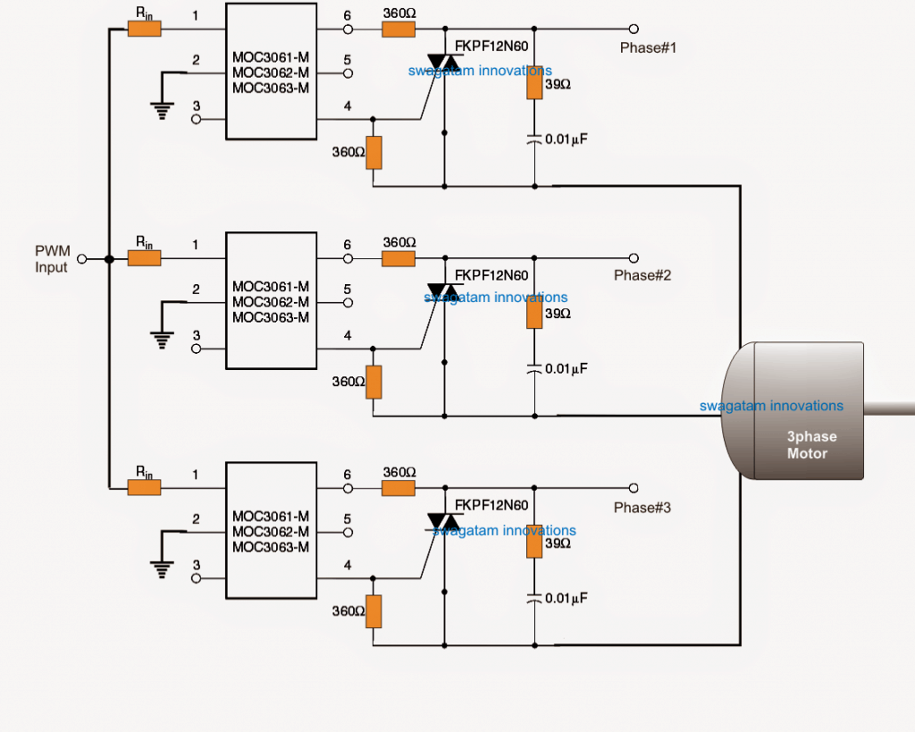
However in case a 3 phase motor is used, the following idea can be used for implementing the proposed 3 phase soft start on motors.



Questions & Answers
Bro just asking, but can you help make a circuit? a pwm motor speed controller with the soft start?
I’m running 775 and 590 motors but the ones from market lebeled as pwm controller doesn’t seem to like work. when I turn the pot from 0, there’s always a twisting jerk in the motors. i want to eliminate that, and run the motor smoothly.
Sure Bro, I will try to design it for you, please let me know if your motors are AC motors and DC motors?? Then I will configure the circuit accordingly..
No it’s simple dc motor but high power.
Talking about johnson 775 and divyanshi 590 dc motor
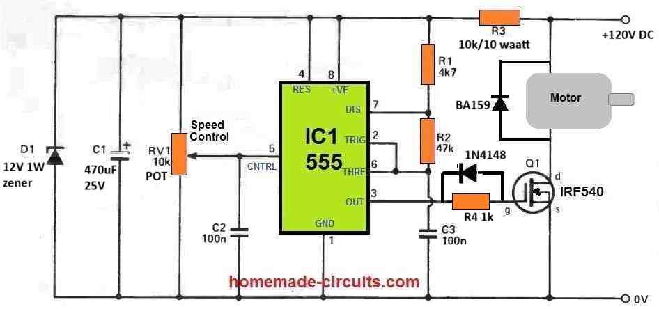
OK, then I think you can try the following concept. Just increase the C2 value to 100uF to get a soft start at the start:
can it handle 24v 20 amp dc?
as my motors are rated for 7 amp minimum when i bought it.
that 12vdc-24vdc , minimum 7 amp, so under load and some upper margin, 20 amp capable I wanna make it
Yes, IRF540 can handle 24V 20 amp load…if possible please add a snubber also across the MOSFET…
https://www.homemade-circuits.com/rc-snubber-calculator-for-mosfets-relay-contacts-and-triacs/
and where do I use mod for direction change? for, forward reverse rotation
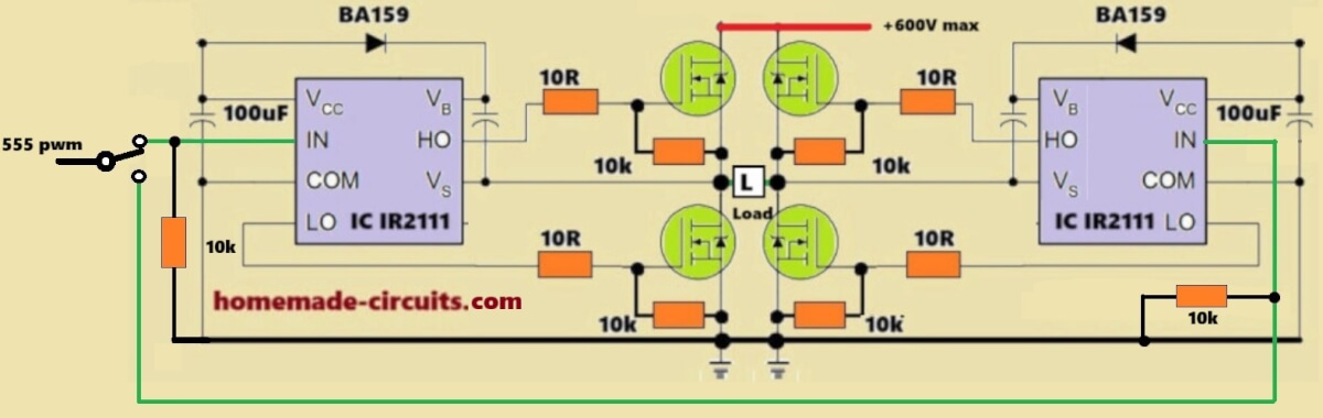
If you want a bidirectional motor control then you may have to go for a dedicated H-bridge driver circuit, such as this one:
The diagram that you emailed me will unfortunately not work…
thank for the suggestion. you are my big bro in my hobby. you really are so helpful 😊🙏
No problem Bivash, you are most welcome…
I would like to use this assembly for my pump, 220 volt 1.5 Ph
Sure, You can try it….
Hello Swagatam. Great article and thanks for your insights!.
I need your help with a soft starter diagram for a 8.4V DC motor. According to the above configuration, I do not have a 2.7v zenner diode. I only have 5.1v and 12v types. Regarding transistor BC557, BC547, I have C1815, A1015, how should I fix it? Is it possible that the 2s 18650 8.4V battery is enough to fully power the motor when reaching max speed?.Thank sir.
Thank you LongE,
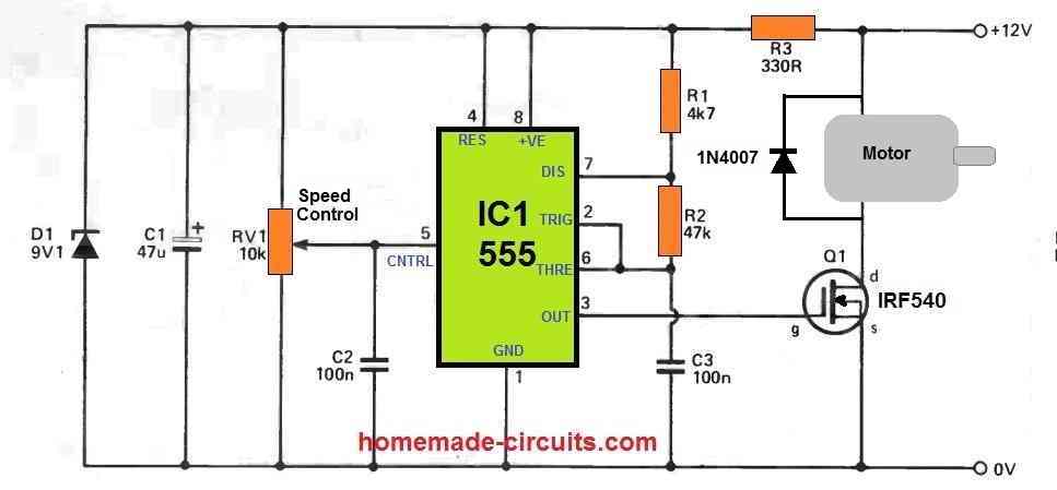
Instead of the above concepts, I would recommend you to first try the following simple design:
In this design just replace the C2 capacitor with a 100uF or a 220uF for generating the soft start.
Furthermore, you can replace the MOSFET with a BJT if required, depending on the current rating of your motor.
2s 18650 8.4V battery should be enough for generating max speed on your motor, assuming the motor current rating is within the battery’s max current delivering capacity….
Thank you sir, So I will change C2 to 220uF and remove D1 Z9,1v ; R3 330 ohms. The no-load starting current of this RS540 motor is 10 Amp and reaches stability at 6 Amp. In my opinion, BJT cannot be used. I’ll try assembling the circuit over the weekend.
No problem LongE, please go ahead, and let me know how it goes…
great article, very useful, simple and easily explained for less experienced people, I am a passionate electronics beginner and I would like to build a mechanism for roller blinds using a triac, but the motor must be able to rotate in both CW/CCW directions. Using your first one, it turns in one direction, and connect the second triac to control the second one.
Thanks for liking the concept, is your motor an AC motor or DC motor?
If it is a DC motor then transistors can be used for flipping the polarity.
Hello
How nice that you replied so quickly 🙂 great 🙂 it’s an AC TYJ50-8A7 CW/CCW motor and I want to use it to roll up and unwind the blinds
Thanks kris, Ok got it, however PWM cannot be effectively used for AC motors with triacs, so that’s the problem…
I am using a12 v dc 1800 watt Nipon Denso geared car starter motor to pre spin 24 foot rotor blades on my gyrocopter are there any off the shelf 12v soft start controllers that are capable of doing this or will i need to get one specially designed ?
I think you will have to get it specially designed. Or you can build and customize the following concept for your application, it should be able to provide you with the intended results:

Sir, this circuit is not effective. It reduces all parameters such as rotation speed, starting current, and current consumption. total reduction. Just like reducing the power supply voltage to the motor. Maybe I should try a 2 ic 555 circuit?
LongE, How did you test the circuit?
First you should test without adding the capacitor between pin#5 and ground, just by using the pot.
If still it doesn’t work then your IC or your circuit might have some problems, because adding a pot with pin#5 of the IC should certainly allow the output PWMs to vary accordingly.
I should have mentioned I do not need speed control just soft start as the starter motor does not have sufficent power to get the rotors up to full speed { the starter motor runs out of puff at around 120 rotor RPM} after which the pre spin is turned off then the forward air speed through the rotors will bring them up to flying speed. Is there a circuit that will just give a gradual increase in motor speed without having to turn a potentiometer { speed control not needed }
OK, in that case you can try the following simplified design:
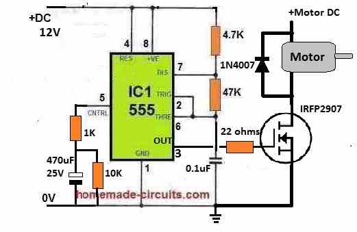
The 470uF capacitor determines the slow start length.
Would any of these circuits work for a 2HP 220VAC pump motor?
The above circuits are for DC motors. For AC motors the following concept might work:
https://www.homemade-circuits.com/adding-soft-start-to-water-pump-motors/
I’m new to using MOSFET and your article is very helpful.
I am looking at powering a treadmill Brushed 4 HP 90 VDC 12 AMP @ 5200 RPM motor from a 80 V, 6 Ah lithium battery with a IRF3710PbF MOSFET. But I’m worried about the inrush power when the controller signal is 100% at start.
Therefore it seems your double 555 design would solve the issue to ramp up (limit) the power to the motor.
Do you see any issue using your laid out circuit for my application?
Thanking you in advance for your help and guidance.
I see no issues with the above soft start pwm concepts and it can be perfectly used for your application
Awesome! Thank you for your quick feedback.
Will return with the result once put together.
No problem, all the best to you.
Hi
I have a PWM modulated clutch in my car. It is electro magnetic in operation and is a sealed unit and there is zero documentation.
I suspect the clutch engages to 100% in an instant rather than smoothly ramping up. I wish to build a circuit as a diagnosis tool to prove or disprove my theory.
So, its a 12V power supply and the supply to the clutch is PWM, presumably by the controller PCB. I have no details about the frequency or any other data about the power supply. My suspicions are that this controller is at fault in the modulation phase.
So, I need to instal a simple, and temporary circuit just before the clutch to slowly ramp up the current say over a one or two second period.
I guess my problem is that I need to soft start and already PWM’c current supply. Grateful for any ideas.
Hi, you can probably try the following circuit for implementing the intended soft start on your clutch device. Please test the circuit with a DC lamp first to verify its working.
Woo Hoo!…..
Many thanks..
I’ll give it a try in the next few weeks.
I am glad to help. Let me know if you have any problems.
Hello Swagatam. Great article and thank you for your insights! I would like to make or buy a soft-starting device for our Leeson 24V, 3/4 HP, 29A 1800 RPM motor. This motor drives hold plate fridge compressor on a boat. I would like this PWM soft starting device to activate and come up to full motor speed at 5 to 10 seconds. I have some EE beginners skils and can build a circuit but I would also consider a well built reliable device I could buy. What would be your suggestion? Thank you! Serge
Thank you Serge, glad you liked it! Making a practical prototype can be difficult for me due to lack of time, I am sorry about it. Nevertheless the circuit has been tested by me, so you can feel free to build it yourself and check how it responds. If you need any further assistance let me know through comments I’ll try to solve them as soon as possible.
Hi Swatam, I am building a cnc milling machine and I have a 400W 48V spindle and a 500W / 48V power supply. I understand that the second scheme with a large heat sink on the transistor is enough to regulate the speed?
Hi Jacek, that’s right, the second idea can be implemented for your application and used for controlling its speed.
Hi Swagatam,
On Integrating a zero Crossing Triac Controller diagram above, the triac FKPF12N60, there are no clue regarding terminal in (T1 / A1) & terminal out (T2 / A2. My view on the diagram, T1 / A1 goes to load / motor – based on standard triac datasheet. On some articles, termial goes to load / motor should be T2 / A2. Or my view is wrong, please advise.
Thanks.
Hi Awak, in the above MOC opto-coupler circuit, the triac A1 should be towards the motor, and A2 should be towards the phase inputs, according to me.
Thank for advice. I’m not an Electronic Engineer, but I deeply interest in electronic since I was a teenage. So please educate about this. Yes, as read in the articles normally triac current run from A1 to A2 terminal control by triac gate. As your answer above, it runs reversely for opto-coupler, please tutor me regarding this.
Thanks.
You are welcome Avak,
There’s no polarity for a triac conduction. The conduction depends on the AC polarity, which may be from A1 to A2 or A2 to A1, so the triac can conduct both ways.
You can learn more on this from the following article:
https://www.homemade-circuits.com/triac-circuits-working-and-application/
Hi
I’m interested in building this circuit to soft start a 120volt rv ac unit (13,500 btu). Will this work for that application?
Thx
Bruce P
Hi, it will work, but since your motor is an AC motor and will require an AC supply, you may have to modify the mosfet section in the following manner:
is the pcb for the said circuit( pwm soft start) avaliable with you.
if yes kindly get me the price.
I am Sorry, PCB is not available with me for this project.
Dear Mr Swag ,
I have been following your suggestions regarding soft start for single phase motors . I’m a retired Mechanical engineer , so am a little out of my depth as far as electronics is concerned , tho am ok with mains electricity !
Before I spend any money I want to make sure I have all the information clearly in mind , I hope you will understand .
My situation is I have some angle grinders that jump out of my hands when I switch on ! ! Very dangerous ! ! The switch to turn on is built into the handle of the machine , I can’t see any space to build soft start into the handle ! My Question Is . . . Is it possible to build a unit to plug into the wall outlet that can turn on when I switch on the grinder at the handle ? ? Sorry if this is a silly question , but I would like to know if it is possible before I get into a muddle ! I’ve just thought . . . Do I have to fit a different cable to the grinder ( 5 core ?) So the switch on the grinder will activate the soft start unit ? , I hope this doesn’t make problems . Jim Simpson
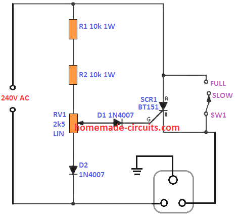
Dear Jim, I think the second circuit from the following article will suit your application well, but you must test it with the `100 watt bulb first to confirm the working of the circuit. L1, C1 can be avoided as they are not necessary, 150k can be tried for the resistor R2, although other values can be also tried for optimizing the initial slow start speed:
https://www.homemade-circuits.com/adding-soft-start-to-water-pump-motors/
However this circuit is just a two-step soft start design, which can still produce some jerk to your hand.
This circuit can be built into a box that will fit into the wall socket.
You will not need a 5 core cable for the above design.
The capacitor in series with the 4k7 resistor decides the initial full speed delay. I have selected 100uF for this capacitor which I think is quite less, you can try using a 470uF capacitor instead of the 100uF to get adequate initial delay for the full speed relay activation