In this post I have explained the datasheet, and the pinout specification of the IC STGIPN3H60 from ST microelectronics, which is perhaps the slimmest and the smartest 3-phase IGBT driver IC featuring in-built IGBTs, rated to work with 600V DC bus and upto 3 amp current, that's equivalent to almost 1800 VA handling power.
3-Phase IGBT Driver IC with Advanced Features
In this website so far we have mostly discussed and incorporated the IRS2330 (or 6EDL04I06NT) for implementing a given 3 phase driver application such as a 3 phase inverter or a BLDC motor controller, and assumed this to be the easiest option using ordinary discrete components.
However with the advent of this new more compact, slim and smart 3-phase driver IC STGIPN3H60, the earlier counterparts appear to be quite outdated, no surprise why this new IC is entitled with the name "SLLIMM" meaning small low-loss intelligent molded
module.
This is especially because the new IC STGIPN3H60 incorporates in-built IGBTs enabling the application designs to become extremely compact and hassle free while configuring the specified parameters.
Let's not waste any more time and quickly learn the main features, and specifications of this smart 3-phase driver IC.
Main Technical Features
1) The device is a 3 phase IGBT full-bridged driver rated at 600V, 3 Amp
2) Comes with in-built full bridge 3 phase IGBT circuit, along with freewheeling protection diodes
3) Features a low electromagnetic interference working
4) Comes with an under voltage lock out, and a smart shutdown feature
5) Offers a comparator for enabling over current and over load cut off protection.
6) Includes an optional opamp in-built for enabling an advanced protection system, if demanded.
5) Possesses an in-built bootstrapping diode.
We might find a few more outstanding features in the device but I will elucidate only the above main features through its pinout functions, for the sake of simplicity.
Application Areas:
The proposed IC can be used for making extremely efficient, and compact units as mentioned below:
3-phase phase inverters
3-phase BLDC motor controller
heavy lifting quadcopters
super efficient ceiling fans
E--rickshaws, and bikes
in robotics etc
Pinout description
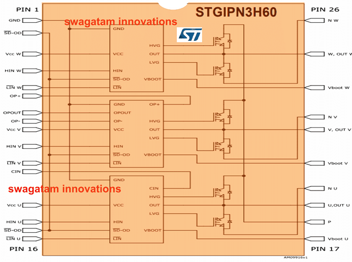
The figure above depicts the pinout diagram of the IC STGIPN3H60, which is a 26 pin DIL IC, we will begin the pinout functioning explanation from the left hand side of the IC.
Pin#1: It is the ground pin of the IC and needs to be connected with the ground supply rail.
Pin#2, 15: These are the SD-OD pins, any of which can be used for shutting down the device through an external sensor circuit for safeguarding the system from a possible catastrophic situation. A "low" signal on this pinout will execute the shut-down operation.
Pin#3, 9, 13: These are the Vcc supply voltage input pinouts, for the 3 internal driver modules and must be shorted together, and connected with a common +15V DC input.
Pin#4, 10, 14: These are the HIN inputs or the high side logic signal inputs, complementary to the LIN inputs or the Low side signal inputs. These pinouts must be fed with a 3-phase alternating 120 degrees apart logic signals from an external source or an MCU, for initiating the motor rotation.
Pin#5, 11, 16: These are the LIN inputs or the Low side logic signal inputs, complementary to the above explained HIN inputs and should be fed with alternating 3-phase low voltage triggering signals for initiating the motor rotation.
The HIN, and LIN input signals must be anti-phase to each other, meaning whenever HIN is high, the corresponding LIN must be low and vice-versa.
Pin#6, 7, 8: These are the non-inverting, output and inverting pinouts respectively of an internal spare opamp which can be suitably configured for executing a required advanced protection circuitry in case the system demands for it, otherwise these pinouts can be left unused, however make sure not to keep these opamp inputs open and floating, rather terminate these OP+, OP- pinouts through an appropriate configuration, to prevent instability across these pinouts.
Pin#12: It is the Cin or the comparator pin of an internal comparator stage, which facilitates processing of a sensed over-current or overload signal generated by an externally configured shunt sensing resistor.
Now let's move on to the right side of the IC and see how the indicated pinouts are designated to function and how these needs to be configured within a given driver application circuit.
Pin#19, 22, 25: These are the output pinouts of the IC, and needs to be connected straight with the specified 3-phase wires of a BLDC motor, regardless of whether the motor involves sensors or not. A motor having sensor wires can be also used with this IC.
In case the motor incorporates hall sensors, the sensor wires could be configured with the HIN/LIN pinouts, through suitable inverting gates, because the corresponding HIN/LIN inputs must be applied with anti-phase or opposite signals for correct operation of the motor, and that's why the signals from each motor hall effect sensors must be bifurcated into +/- using NOT gates for feeding the respective HIN/LIN complementary inputs of the IC.
Pin#20, 23, 26: These pinouts are the negative supply inputs for the corresponding 3-phase motor outputs, and all these pinouts must be joined together and connected with the common ground (motor bus voltage ground and IC pin#1 ground)
Pin#17, 21, 24: These are the Vboot pinouts and are required to be connected with a high voltage capacitor also referred to as bootstrap capacitor. The 3 capacitors must be configured across these pinouts and pin#19, 22, 25 or with the corresponding outputs from the IC. In general any 1uF/1KV capacitor can be used for these caps.
Pin#18: This pinout is the bus positive supply pin, and must be attached with the motor positive supply input, which can be anything between +12V to +600V.
The above details comprehensively explain the working, the features and the pinout specification of the compact, slim 3-phase IGBT full bridge driver IC STGIPN3H60 from ST Microelectronics.
If you have any specific question or doubt regarding the practical implementation of this device, do not hesitate to put them forth in the below given comment box.
In a few of my upcoming articles I may additionally explain how this special 3-phase IGBT full bridge driver IC could be applied for driving high power BLDC motors, inverters, and other gadgets such as high capacity drones.

Questions & Answers
I know your a guru in electronics and I want you to guide me convert a single phase (220v) to three phases for ac motor of 3.5kva?
What about your 12v dc circuits for switching 330v mosfets. Have seen some ccts. on your web do not know if it is sine wave.
Can you specify the circuit, can’t figure out which circuit are you referring to?
Thanks, but I am not a guru in 3 phase circuits, so not sure how to solve your problem.
I have a nissan Leaf EV and need a L3 (fast) chademo charger for the traction battery. The battery voltages when charging ranges between 325V When fully discharged and 395V When charging full bore.
Could I just gang many of these together to get ~~50kW(about 200A from my 240V dedicated mains)? or is there an easier way to do it? Also, Is there some way to get it work on the now more common CCS or tesla charger when away from home? Will my utility complain for this use of the mains? My home has 2x 200A circuit panels on one meter with nothing required to be on one of them. Anyway, I use it! & I suspect that with 11 car manufacturers claiming to be going ALL ELECTRIC within 2 years of a date 8 months ago. I suspect there will be many people needing to try this.
I suspect that this is essentially a DC welder with a Raspberry Pi or arduino processor controller and a CANbus connection to the car.
Also, I want to upgrade the 24 kWh battery (with 12.5 kWh usable capacity) to 62kWh using a MUXsan canbus repeater.
Any ideas would be very much apreciated.
Yes you can gang them up making sure that the maximum current remains within the safe limits of the battery specs. 200 Amps is huge, so maybe the utility will come to know about the situation and decide to send you a notice, or probably they may start sending you bills charged with extremely high rates.
Sorry I do not know much about the MUXsan system so can’t provide my suggestions on this.
Estou aguardando ansiosamente por um circuito de controle motor bruchules de 92V com encoder.
Grato!
I will try to find!
The problem is that with this IC, you can only build a VFD that uses less than 3A. If you need more than 3A, you still need a separate driver and set of IGBTs so it is not a like for like alternative
Hello Swagatam,
First, thanks so much for this site – it’s an incredible resource for any/all electronics enthusiasts.
In several of your posts about 3-phase motor drives, VFDs, Inverters, etc. you make reference to the incoming HV supply (i.e. 230-325VDC) but I haven’t found a post where you expand on how to handle when rectifying AC mains. I’m wondering if you have more insight/info you can share on the AC-DC rectification, inrush current limiting, capacitor/inductor sizing, etc. My application involves a 10HP(7.5kw) 3 phase induction motor which I’m looking to power from 230v 60hz single phase. Needless to say, I’m well aware of the dangers of non-isolated connection to mains and always take necessary precautions. I’ve found some references to using NTC thermistors and SCRs for inrush limiting but not a lot of practical application insight. Any help is greatly appreciated.
Best regards,
Tom
Hello Tom, Glad you liked my website and thanks for your feedback!
The basic and the traditional way of rectifying the 3 phase AC mains is by using a 6 diode bridge rectifier and a 22uF/630V capacitor. This should work efficiently for the required AC to Dc conversion. The capacitor value could be increased to any desired value depending on the space available for the design.
As you mentioned inrush current could be controlled using heavy duty industrial MOVs or additionally with inductor and capacitor networks.
Dear sir!
I build 3phase inverter it’s work but 1 phase work correct and 2 phase up and down volt. Using these parts
Mosfet,ups card for Base order and ic 2110 please guide
Dear Azlan, it can be difficult for me to judge the fault because I cannot verify which stage may be malfunctioning, whether it’s the IC stage or the UPS card. you can try Checking the UPS card output separately on a 3 phase scope to verify the waveform
Dear sir,
I need solar vfd inverter 3 phase 380 v diagram with parts list
Hi Muhammad, you can study and try the last diagram presented in the following post:
https://www.homemade-circuits.com/single-phase-variable-frequency-drive/
you can also study the following concept:
https://www.homemade-circuits.com/3-phase-vfd-circuit/
Dear sir, my best respects to you. I have need a 2000w dc24v to ac 380 v 3 phase igbt drive inverter circuit diagram . How output power of igbt STGIPS30C60 ? May I get a complete igbt drive schematic circuit diagram with parts list ? If possible send to my e-mail address, ” imdad4265@gmail.com . Thanks.
Aristarcus.
Hi Aristarcus, I’ll try to update it soon