In this post I have explained what servo motor is, how it functions, how to interface with microcontroller and what make this motor special from other motors.
Being an electronics enthusiast we would have come across many kinds of motors, here we are going to take a look at special type of motor called servo motor.
What is a Servo motor?
Servo motor or simply servo is a special type of motor which is designed for precise control over position, acceleration and velocity. Unlike all other types motor, servo can only rotate 180 degree bi-directional. It has mechanical gears and stopper which limit the angular rotatory of servo.
Typical servo motor:
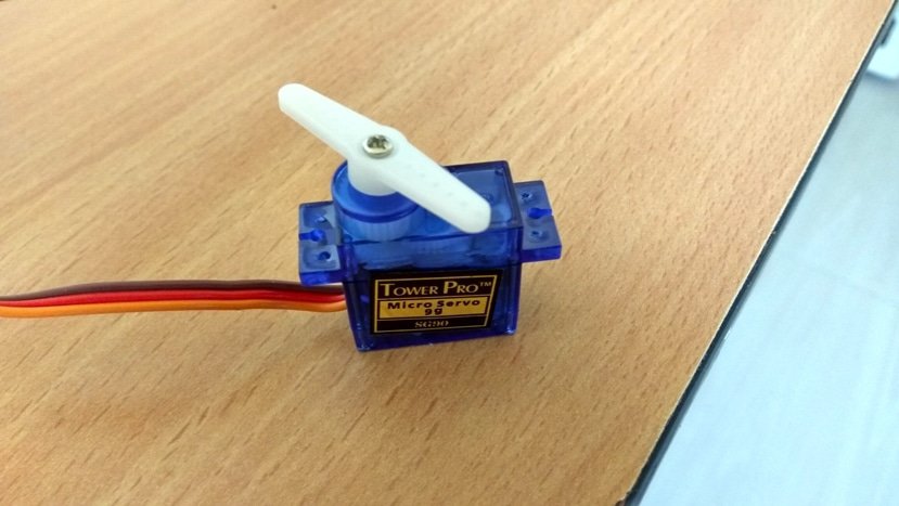
The servo motors are used in robotics, CCTV cameras, RC cars, boats, toy aircrafts etc. Servos are used where we no need continues rotatory motion, but lock in a specific position or move some load with controlled velocity within the moveable angular limit.
Servo aren’t simply a motor like other types, but it is module, which combines of a normal DC/AC motor, a group of gears, control electronics and a feedback system. Let’s look at the each mentioned stages in detail.
DC/AC motor which is employed on a servo module can be brushless or brushed motor, on most of the hobby servos DC motor is used and AC motors are used in industrial applications. The motor gives rotational input to the servo. The motor rotates at several hundred RPM inside the servo and output rotation is about 50 or more times less of its RPM.
The next stage is the gear assembly, which control the angular rotation and speed of servo. The gear may be made from either plastic or metal depending on how bulky the load is. Generally DC motors are run at high RPM and low torque; the gear assembly will convert the excess RPM into torque. Thus a small motor can handle a huge load.
The next stage is control electronics which constitutes of MOSFETs and ICs for controlling the rotation of the motor. A feedback system is always present in servo motors for tracking the current position of the actuator.
In servos generally a feedback component is a potentiometer, which is directly connected to rotating actuator. The potentiometer acts as voltage divider which is fed to the control electronics. This feedback helps control electronics to determine the amount of power given to the motor.
A servo motor in a fixed position will reluctant move from its current position if any external force try to disturb. The feedback system monitors the current position and powers the motor against external disturbance.
The above scenario is same when the servo is moving its actuator. The control system will compensate the external force and move in determined velocity.
By now you know quite a bit about servo motor and its functioning mechanism. Let’s see how to control the servo motors using microcontroller.
Servo motors have 3 terminals unlike other motors which have 2 terminals, two for supply (5V nominal) and one for control signal. The wires are coloured for easy identification of terminals.
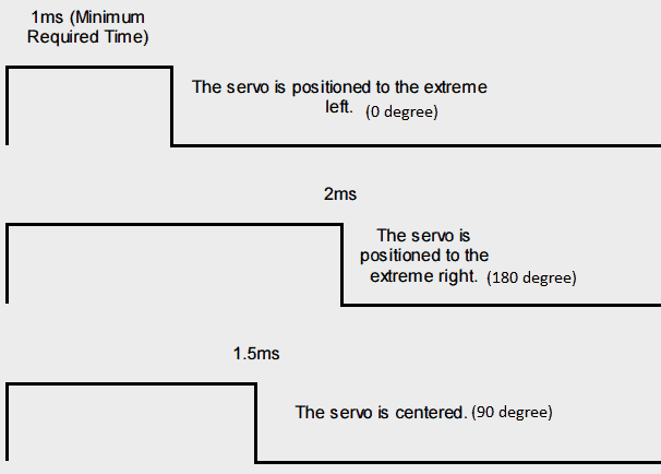
The control signals of servos are PWM at 50Hz frequency. The pulse width of the signal determines the position of the actuator arm. A typical hobby servo motor operates from 1 to 2 milliseconds pulse width.
Applying 1 ms pulse width control signal will keep the actuator at 0 degree position. Applying 2 ms pulse width control signal will keep the actuator at 180 degree position. Applying signals in between 1-2 ms will keep the actuator within 0-180 degree angle. This can be better understood by given below image.
By now you would have understood how a servo is controlled by pulse width modulation (PWM).
Now let’s learn how to interface a servo motor with Arduino.
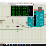
Circuit diagram:
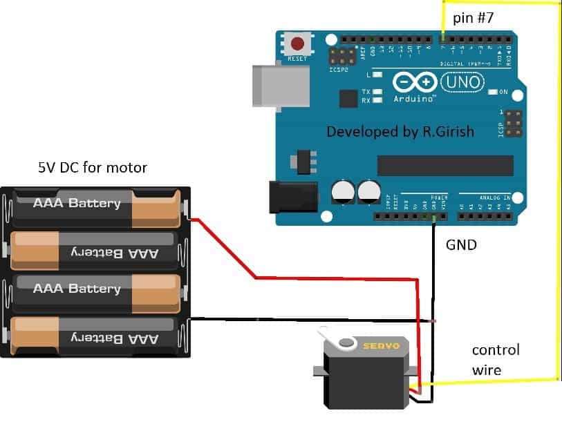
The wiring is easy and self-explanatory. You need external power supply if you are using a bulky servo motor. If you try to power from arduino power’s supply you will end-up overloading the USB port on the computer.
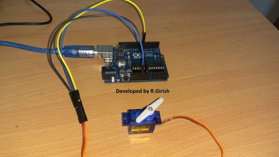
If you have servo similar which is illustrated at the beginning of the article, then you may power it from arduino 5V supply, also shown in author’s prototype.
Author’s prototype:
Arduino need servo library for handling it, it made our task easy and it’s already in the Arduino IDE.
Program:
//--------Program developed by R.Girish--------//

#include <Servo.h>

Servo motor;

const byte servoPin = 7;
const int t = 10;      // Servo speed (lower value = faster)

void setup()
{
    motor.attach(servoPin);
    motor.write(0);     // Start from 0 degrees
    delay(500);         // Allow servo to reach starting position
}

void loop()
{
    // Sweep from 0° to 180°
    for (int pos = 0; pos <= 180; pos++)
    {
        motor.write(pos);
        delay(t);
    }

    // Sweep from 180° back to 0°
    for (int pos = 180; pos >= 0; pos--)
    {
        motor.write(pos);
        delay(t);
    }
}

//--------Program developed by R.Girish--------//
The above program will sweep the actuator 0 to 180 degree right and 180 to 0 degree left and cycle repeats. This is a simple program for testing the servo; you may need to write your own code for your customized applications.

Questions & Answers
Hi,
I will try make a article regarding stepper motor soon.
Regards
Hello Very useful tutorial for me. As I working on project which contains servo and stepper motor so can you share working and circuit diagram of stepper with Arduino nano. Thank you.
Hello Swagatam this Is Kuldeep And i want a simple fm transmitter circuit which we use to make a project and this tarsmition is also catch by mobile fm Radio please help me
hello kuldeep, you can try the following idea,
https://www.homemade-circuits.com/2012/01/how-to-make-wireless-speaker-system.html