In this post we investigate what's a BLDC motor and subsequently I have explained regarding the design of a sensorless BLDC motor driver circuit.
BLDC CPU Fans
Seen those fast moving fans in CPUs, voltage stabilizers, DVD players, and other similar equipment, which work with utmost efficiency, consuming minimum space, current and yet are able to deliver the important operations as stipulated for the particular equipment?
Yes, these are all the modern versions of BLDC fans or the brushless DC motors which are much superior than the old traditional brushed motors.

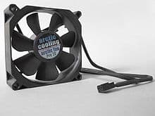
Image Courtesy: https://en.wikipedia.org/wiki/Computer_fan#/media/File:Geh%C3%A4usel%C3%BCfter.jpg
However a BLDC motor will require a sophisticated driver circuit, and yes all these CPU fans contain these driver modules in-built, although these appear easily operable using an ordinary DC, internally the system is already fitted with a smart circuit.
BLDC Motor Driver
Here I have explained about one such smart BLDC motor driver circuit, using a single chip DRV10963 for driving any small BLDC motor with incredible efficiency, and later on in one of the upcoming articles we will see how this IC circuit may be upgraded for driving even the powerful high current BLDCs such as the ones which are used in quadcopters.
But before this it would be interesting to learn a bit about BLDC motors.
Difference Between Brushed and Brushless DC Motors
The difference between a brushed motor and a brushless motor and the efficiency rate is rather obvious.
Since brushed motors have the wound armature itself moving between magnets, has to employ "brushes" (rubbing contacts) so that the moving coil terminals are able to receive the supply voltage consistently without having to reach the supply source themselves, which would otherwise make the working impossible and jeopardize the operations.
In a brushless motor, the coil or the winding is never moving and is constant, here the rotor carries a set of permanent magnets and rotates in the influence of surrounding winding's magnetic fluxes.
Since the magnet is free from all the hassles, and is able to work without involving terminals to manage or to receive power, it can go about effortlessly, spinning at a rapid speed and virtually at a noiseless level.
But there's a catch here. In order to make an electromagnet respond to a permanent magnet's fluxes, there needs to be a constant shift of magnetic phase or poles, so that the two counterparts are able to constantly react and go through an opposing force thereby releasing the required torsional force over the rotor and execute the rotation with the resultant torque.
In a brushed motor, this becomes easier due to the self adjusting nature of the armature coil which is able to rotate and create a self sustaining opposing magnetic force and keep rotating without the need of any external pulses or processing.
However in a BLDC this becomes a problem since the magnet rotor remains "clueless" and requires a calculated magnetic command from the winding in order to rotate in a meaningful way and not in a haphazard manner.
That's exactly why all BLDC motors mandatorily require a motor driver circuit for commanding the three distinct sets of winding inside the motor.
Thus all BLDC are essentially 3-phase motors and compulsorily require 3 phases for producing the rotational torque on the rotor.
What Does Sensorless BLDC Drivers Do
The sensor less BLDC driver circuit simply electrifies the 3 sets of winding in a sequential manner such that the magnetic rotor is able to go through a consistent opposing force enabling the motor to accomplish a sustained torque and rotational force.
But this sequential powering of the BLDC winding by the circuit cannot be just randomly set, it has to be in tandem or in response to the rotational position of the rotor magnet, otherwise the implementation could go haywire and we may witness the motor shaft (rotor) rotating haphazardly, that is jerking in between a clockwise and an anticlockwise with no sensible rotation.
Why Sensors are Used in BLDC Motors
Therefore, we introduce sensors positioned inside many BLDC motor variants, these sensors (typically Hall effect sensors) "understand" the changing position of the magnetic poles of the rotor magnet, instruct the attached processor circuit to electrify the corresponding winding and execute a rotational movement with an optimal torque.
Hall effect sensors are effectively employed in most BLDC motors which are relatively larger in size, but for smaller motors such as in CPU fans, CPU drives, DVD players, in small exhaust fans, for motors used in quadcopters, hall effect sensors can become inappropriate and therefore an alternative sensor less approach is implemented.
This involves the exploitation of the winding's inherent back EMF electricity which is taken as the reference source for processing and electrifying the relevant sets of winding and executing the rotational torque.
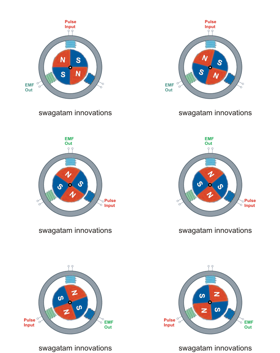
Simulating a BLDC Rotor Movement
In the above crude simulation we can visualize how the released back EMF is taken as the reference and used for producing the sequencing pulses for the subsequent sets of winding, imposing a rotating torque on the central permanent magnet rotor. The simulation might not be the exact replication, nevertheless it gives a rough idea of the working principle.
It is interesting to note that the pulse is switched when the N/S of the magnet is exactly at the center of the winding core, which enables the winding to either energize as N or S depending on the pulse polarity and produce an attracting and repelling force on the N/S magnets, thereby generating the required torque at the maximum possible level.
And this in turn becomes possible due to the back EMF released through the switching of of the previous winding.
The above discussion clarifies the working of a sensor less BLDC motor, now I have explained how a specified circuit handles the above complex execution of a 3 phase switching
BLDC Driver DRV10963
After some Googling I found this sensorless BLDC driver circuit using a single chip DRV10963 which employs negligible amount of parts in the configuration and yet is able to implement a sophisticated processing for the intended actions.
The DRV10963 is a state-of-the-art chip which is specifically designed to operate sensor less BLDC motors by merely anticipating the back EMF from the motor winding and delivering a precise command over the winding and accomplishing an optimal rotational torque over the rotor.
Circuit Diagram
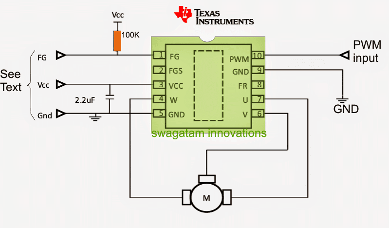
The above image shows the simple layout of the circuit which apparently includes nothing but the IC itself.
The various pinouts are allocated for carrying out the specified functions such as PWM speed control of the motor, direction control, etc by simply feeding the relevant pinouts with the specified datas from an external source.
The following image shows the package of the chip, which looks like a 10 pin DIL IC, the various pinout functions of the same may be studied from the data as furnished under the diagram:
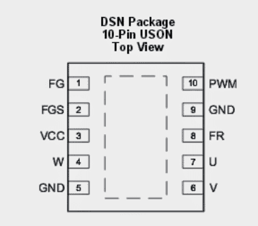
Referring to the circuit diagram of the proposed sensorless BLDC driver circuit as presented in the previous article and also the chip image above, the pinouts details may be understood as follows:
IC Pinout Details
FG = It is the motor speed indicator pin (output), which is rigged in an open collector mode with an internal BJT.
Open collector signifies that the output at this pinout will produce the negative PWMs through sinking logics across the open collector and ground, thus to get a valid reading the user will need to connect a pull up resistor across this open collector and the positive supply (5V) for accomplishing the speed indication at this pinout.
FGS = It's the speed indicator selector input, meaning a logic high or low may be introduced here for switching ON/OFF the indicator pin FG.
Vcc = The positive supply to the IC for enabling it to operate, must not exceed 5V.
W, U and V are the 3-phase outputs for the BLDC motor which is supposed to be operated through this IC. This also acts like inputs for sensing the motor EMF pulses for the required synchronized switching of the motor coils.
GND = Refers to the negative supply pinout of the IC with respect to Vdd pin.
FR = Helps to select or command the direction of the motor and may be dynamically changed anytime once the system is powered, simply by introducing an external logic high or logic low.
PWM = It signifies the PWM control input from an external PWM waveform generator.
This PWM input may be variable for implementing the desired speed control of the connected BLDC motor.
The dotted space at the center of the chip indicates the thermal pad, which may be clamped or pressed with a heatsink in order to sink the possible heat generation on the chip while its being used with a loaded BLDC motor.
The above discussion states the pinout or the connection details of the sensorless BLDC motor driver chip DRV10963, now let's analyze the internal configuration and functioning of the chip in detail with the help of the following points:
Device Description
The DRV10963 is a 3 phase sensorless electric motor operator with built-in power MOSFETs (3-phase H-bridged). It is tailored for higher productivity, reduced noise and minimal secondary material count motor drive functions. The exclusive sensorless window-Iess 180° sinusoidal management scheme delivers noise-free motor commute efficiency.
The DRV10963 made up of an smart lock detect functionality, put together with supplementary in-built security circuits to achieve secured performance. The DRV10963 can be found in a thermally efficient 10- pin USON packing with an uncovered thermal mat.
How the IC Works
The DRV10963 product is a 3 phase sensorless motor operator with infused power MOSFETs, It is
created specifically for superior performance, reduced resonance and minimum superficial part count motor drive functions.
The principal sensorless window-less 180° sinusoidal control plan presents noiseless motor functioning by maintaining electrically stimulated torque ripple nominal. Upon initialization, the DRV10963 device is going to turn the motor in the course specified through the FR input pin.
The DRV10963 chip is going to function a 3 phase BLDC motor making use of a sinusoidal control plan.
The significance of the employed sinusoidal phase voltages depends upon the duty cycle of the PWM pin. While the motor moves, the DRV10963 IC delivers the velocity data at the FG pin.
The DRV10963 unit consists of a smart lock sense capability. In the event like that in which the motor is stunted by an extraneous pressure, the program is going to identify the locking problem and will take measures to safeguard on its own along with the motor.
The particular procedure of the lock sense circuit is depicted in detail in Lock Detection. The DRV10963 IC furthermore includes multiple in-built safety circuits for example over current protection, over voltage protection, under voltage protection, and over temperature protection.
Characteristic Explanation
Speed Input and Control
The DRV10963 presents 3-phase 25-kl-lz PWM outputs which may have a standard percentage of sinusoidal waveforms from phase to phase. In case any cycle is determined with regards to ground, the waveform detected are likely to be a PWM protected sinusoid combined with 3rd order harmonics as shown in Figure 2.
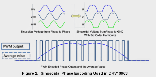
This coding strategy streamlines the driver specifications for the reason that there will probably often be one phase output that could be on par with zero.
The outcome amplitude varies according to the supply voltage (VCC) and the mandated PWM duty cycle (PWM) as defined in Equation 1 and highlighted in Figure 3. The optimum amplitude is implemented once the instructed PWM duty cycle is 100 PERCENT.
Vphpk = PWMdc > < VCC
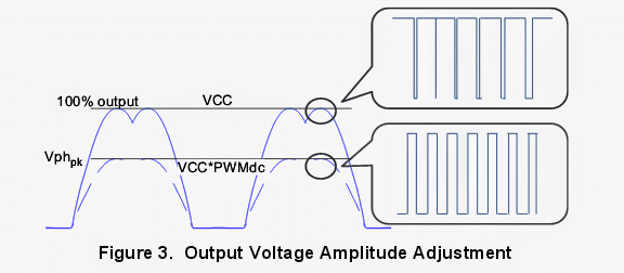
The motor speed is regulated not directly through the use of the PWM order to regulate the amplitude of the phase voltages that happen to be used for the motor.
The duty cycle of PWM input is modified into a 9 bit digital quantity (from 0 to 511).
The regulation resolution is 1/512 == 0.2%. The duty cycle analyzer facilitates an initial order exchange operation amongst the input duty cycle and the 9 bits digital figure.
This is highlighted in Figure 4, in which r=80 ms.

The exchange performance between the PWM ordered duty cycle along with the output maximum amplitude is variable in the DRV10963 device.
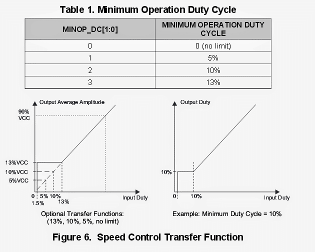
The outcome maximum amplitude is discussed by Equation 1 when PWM command > minimum functioning duty cycle. The lowest operation duty cycle often is established to possibly 13%, 10%, 5% or no restriction by OTP setting (MINOP_DC1:0).
Table 1 demonstrates the recommended configurations for the minimal operation duty cycle.
Whenever the PWM instructed duty cycle is less than lowest functioning duty cycle and more than 1.5%, the output is going to be regulated at the minimal operation duty cycle. Any time the input duty cycle is under a 1.5%, the DRV10963 device will likely not run the output, and is sent to the standby mode.
This can be illustrated in Figure 6.
Rotational Configurations
DRV10963 will start the motor by means of a technique that is finely detailed in Figure 7.
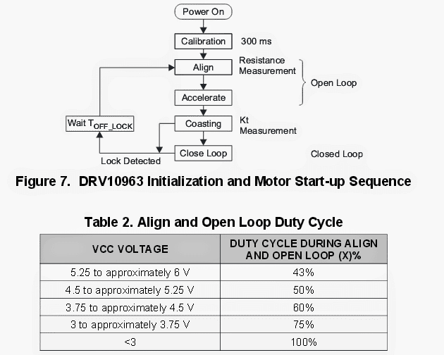
The motor initialization graph consists of device configurable alternatives for open loop to close loop changeover limit (HOW.), align time (TAHQH), and accelerate rate (RACE).
To line up the rotor to the commutation logic the DRV10963 executes an x% duty cycle on phases V and W at the same time controlling phase U at GND.
This scenario is sustained for TAIign seconds. The x% significance is identified by the VCC voltage (as shown in Table 2) to keep up ample rotational torque over various different supply voltages.
As the align sequence accomplishes, the motor is forced to speed up by putting on sinusoidal phase voltages with peak levels as illustrated in Table 2 and boosting by means of the commutation range at an expanding rate represented by RACE until the level of commutation grows to Hom., Hz.
AS soon as this limit is arrived at, the DRV‘l0963 converts to closed loop mode whereby the commutation drive progression is recognized by the in-built control algorithm while the employed voltage is identified by the PWM mandated duty cycle input.
The open loop to close loop changeover limit (Hom), align time (TAHQH), and the accelerate rate (RACE) are configurable through OTP configurations.
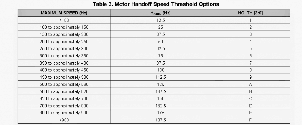
The selection of handoff threshold (HOW,) are typically approved by trial and error assessment. The objective would be to prefer a handoff tolerance that could be as little as feasible and enables the motor to effortlessly and faithfully changeover between the open loop acceleration and the closed loop acceleration.
Commonly increased speed motors (maximum speed) necessitate a superior handoff tolerance due to the fact elevated speed motors comprise decreased Kt hence more affordable BEMF.
Table 3 demonstrates the configurable preferences for the handoff tolerance. Highest speed in electrical Hz are proven as a reference to help out with choosing the desirable handoff speed for a specific submission.
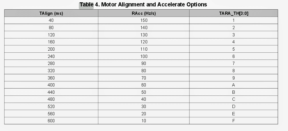
The choice of align time (TAHQH) and accelerate rate (RACE) can even be contingent on trial and error examination.
Motors with greater inertia normally demand an extended align time and a more sluggish speed up rate in contrast to motors with low inertia that commonly demand a briefer align time together with a speedier accelerate percentage. Program tradeoffs needs to be implemented to capitalize on launch stability as opposed to rotate up period.
TI endorses starting with deciding on the less intense configurations (slower RACE and significant Tmign) to compromise the torque up time in support of maximum fulfillment rate.
As soon as the equipment is confirmed to perform conscientiously the extra forceful configurations (greater RACC and lesser TAHQH) may be used to diminish the turn up moment and at the same time cautiously keeping track of the fulfillment rate.
Table 4 exhibits the configurable settings for TA"g,, and RACE.
The remaining part of the explanation regarding this sensorless BLDC IC is furnished in this original datasheet
Please feel free to comment to know more regarding the above discussed sensorless BLDC motor driver circuit details

Can you modify the DRV10963 to work on 48v at least 2000w? by coupling it with some power mosfets, if it is possible how do i impliment it? Thanks
It can be probably done by feeding the 3 phase output from the DRV IC to the input of a 3 phase motor driver IC such as IRS2330
considering the 3 outputs, can i use some power transistor to act as power amplifier for higher output current
Yes you can probably connect p channel and n channel mosfets in a manner as shown in the last diagram of this article;
https://www.homemade-circuits.com/3-phase-solar-submersible-pump-inverter/
hello sir,
i am Ankush Kumar. and i employee in Quantum Hi Tech private limited as a R&D Engineer.
i have also read you Ideas,projects,And so on.
i need to know which software you used to design schematics, PCB, real time simulation?
please tell me because i use Altium designer,protel,Cadance allegro Eagle.
I need your help to innovate new devices. I requested to you.
thanks regards
Hello Ankush,
I do not use any special softwares, or simulators, I draw them using Windows “paint”
Hello, i am trying to make a 3 phase axial (pancake type) motor. However when I connect it to a ESC, it does not rotate although it jerks a little bit. The motor is a 6 pole stator with 8 pole magnets on the rotor. Please advise
It can be difficult to judge the fault without checking the circuit practically….not sure about it!
Hi I am trying to run a whashing machine lg drum motor I+have tried different off the shelf conponents with no luck .i can put together simple circuits ,can you suggest a circuit to achieve this. thanks ray
Hi, sorry, I have no idea how to wire this motor with a circuit.
Please rply me sir can it is possible aur not.. Otherwise if any simple cricuit diagram for runing this small 12v burushless dc motor.. Please provide me..
you can try any of the following designs:
https://www.homemade-circuits.com/?s=sensorless
https://www.homemade-circuits.com/universal-esc-circuit-for-bldc-motors/
I have 12v dc burshless motor… But the problem is it was not run because their hall sensor effect transistor would be burnt out… I want to run this motor without any cricuit how to connect the three wire to the 12v battery please rply me and suggest me how i can do.??
later on in one of the upcoming articles we will see how this IC circuit may be upgraded for driving even the powerful high current BLDCs such as the ones which are used in quadcopters.
Thanks so much Mr. Majumdar. Very helpful. Have you written the follow up article that you speak of?
Regards,
Amit
thank you Amit, No I have not yet written it, my idea was to run a small dummy BLDC motor with the above explained IC, and then feed the back EMF signals from its wires to the input of any powerful BLDC driver IC.
Actually t is not necessary to receive feedback signals for driving a sensorless BLDc, it can also implemented by creating an external sequencing 3phase signal and apply it to any standard high power BLDC driver IC.
"later on in one of the upcoming articles we will see how this IC circuit may be upgraded for driving even the powerful high current BLDCs such as the ones which are used in quadcopters."
Thanks so much Mr. Majumdar. Very helpful. Have you written this follow up article that you are speaking of?
Regards,
Amit
Hi. Can we use the above circuit for 2200kv BLDC for quadcopter?
no, it's for small PC fan motors…
Hola buenas tardes. Voyiniciandome en esto de los motores y quisiera saber si pidieras desir donde en berdad puedo encontrar un diagrama de circuito para un motor brushless.
De antemano gtasias
Hi bro, can we use the above circuit for cd-rom motor. it was brushless with more than 3 wires. please give some info about how to drive those motors without expensive gadgets.
Hi Surya, if your motor is without hall effect sensors then it can be used with the above explained circuit