In this post I have explained a simple programmed reverse forward motor circuit which is used for accomplishing a toy application. The idea was requested by Mr. Matthew.
Technical Specifications
I am a new follower of your website which is a great resource!
I need your help designing a circuit please.
My daughter has a project for school which is a motorized vehicle. I would like to be able to build a 2 stage timed circuit where a momentary switch would activate a forward motion for a few seconds.
Then reverse the polarity for a reverse action for a few seconds. The motor voltage would be 3v. It would be extremely helpful if you could assist this build. Thank you in advance.
Matty.
The Design
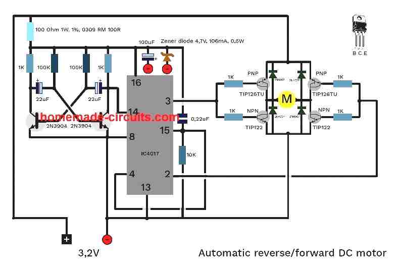
The proposed motor toy circuit which features an automatic forward reverse actuation using a sequential delay timer circuit can be visualized in the following diagram:
Referring to the above diagram, the T1, T2 stage along with the associated components form an astable multivibtator with an oscillator frequency period corresponding to the desired motor reverse forward timing period.
The TIP127 stage is the latch circuit for enabling a push button start for the circuit.
The IC 4017 executes the forward and the backward pulses for the transistor driver stage comprising of Q1-----Q4.
The transistor driver is configured as a H-bridge for facilitating the reverse forward motion of the motor in response to the triggers received from the IC 4017 outputs.
The circuit can be understood with the help of the following explanation:
When the push button is pressed momentarily, T3 receives a short ground pulse through the switch which initiates the transistor turning it ON and supplying a positive pulse to the circuit.
The initialization trigger causes a logic low to appear at pin4 of the IC 4017 which holds and latches T3 into a solid ON position even after the push button is released.
Simultaneously pin15 also receives a positive pulse resetting the IC such that pin3 begins with a logic high.
With pin3 initially high actuates the H-bridge and the motor in a particular direction depending upon the polarity of the motor wires across the bridge network.
Now T1 and T2 begin counting and the moment their set time lapses, pin14 receives a triggering pulse from the collector of T2 which forces pin3 high logic to shift to pin2.
The above condition instantly reverts the H-bridge polarity and causes the motor to initiate an opposite course of its motion, until the next pulse at pin14 of the IC arrives.
As soon as the subsequent pulse is sensed at pin14 of the IC 4017, the high logic at pin2 of the IC now moves a step ahead and settles at pin4 of the IC.
However since pin4 is associated with T3, a high at this pin immediately switches OFF T3, consequently breaking the latch and switching OFF the power to the entire circuit.
The toy motor circuit now entirely switches OFF until the push button is pressed again.
A 0.1uF capacitor should be connected in parallel with R2 so that each time power is switched ON T2 triggers ON first and enables a correct implementation of the system in terms of the set time intervals.
Video Proof
Adjusting the Time Delays
The time intervals can be set or adjusted as per user preference by altering the values of either R2/R3 or C1/C2 or both of these pairs.
Although the circuit is implemented as a toy here, it may have many interesting industrial applications and can be modified for executing several user specified programmed machine activations.


Questions & Answers
What are the red and yellow diodes under R5 and R6?
Those are red LEDs!
Hello sir,
I followed the circuit with TIP122 and 127 and the motor runs with good timing. Kindly suggest how to reduce the time for CC/ CCW rotation. I mean whether by reducing the capacitor/ R2 R3 resistor values or by increasing the values. do mention if you have tried any of them for reducing the speed apart from the values used in the original circuit.
Hello Murali, glad to know it is working now. To reduce the CW/CCW timing, the clock pulse will need to be made faster, which can be done either by reducing the values of R2, R3, or the values the of C1 and c2, or all the 4 components.
Hello Martin,
Is it possible to adapt this circuit for a 3000rpm DC motor? I am interested in building my own watch cleaning machine that uses this type of automatic forward reverse actuation.
Yes it is very strange…
I try to put bases of each side (TIP122/126) together and put one 1K resistor to pin2 and second 1K to pin3. Now it works (also in reverse), but still with extreme overheating of transistors.
The only possible issue I can see is the dead-time between the pin2/pin3 transition. In 4017 the transition may not have a proper dead-time….meaning a brief moment between the pin2 pin3 switching when all the transistors are totally OFF….this ensures all transistors do not conduct together even for a microsecond during the transition period.
You can try using IC4047 instead, which has all the features in-built, just configure the IC and hook up the H bridge across the output pins, and hopefully you may get the results instantly….
“Motorized Jewelry Box Drawer Opening and Closing Circuit”
I just started following your website and I can learn a lot from the great designs you have.
I need your help to modify the circuit named: (Toy Motor Circuit with Timer).
I would like a modification of that circuit to accommodate a jewelry box with a timed motorize drawer opener circuit where a momentary switch would activate the forward opening motion, and stop when it is fully open.
Then closes only when the momentary switch is pressed again. The motor voltage is 5 volts.
It would be extremely helpful if you could assist me with this build.
Thank you in advance
Using a single switch can make the circuit quite complex, instead you can use two switches (close/open) for this, and a couple of limit switches to stop the motor at the end limits, as shown below:
https://www.homemade-circuits.com/simple-gate-openclose-controller-circuit/
Hi Swagatam, thank you!
I understand what you mean when you say that using a single switch will make the circuit very complex, and there is an easier way; so I will go with the simple gate open and close controller circuit that you’ve sent. I understand clearly the operation of the circuit so now I can go ahead and complete the build and set the limit switches in it’s proper place. I am using an old DVD player as the mechanism for the drawer open/close unit, the draw itself is very lightweight.
Michael
Thank you Micheal, I am glad you could understand the concept and are ready to implement it practically.
Hi, thank you!
this is exactly what I was looking for, but please help me (noob alert)
can I use:
– pnp 2N2907 (instead 2N2907)
– npn 2N4401 (instead 2N2222)
– CD4017 BE (instead IC4017)
– TIP126 (instead of TIP127)
– capacitor 0,22uF from pin 15 – must be ceramic? If yes, can I use 22pF?
– the “IC” on your scheme means pin 8 right?
You are welcome! Yes those equivalents are just perfect, although the motor driver transistor ratings will depend on the motor specs. For the shown values the motor current rating should not be above 200mA
So I dont know What I am doing wrong 🙂
I have attached 3-6V 75mA geared DC motor. Input: 3,2V 1500mA
Now I using electrolytic 0,22F capacitor : minus to pin15, plus to pin 16. Should I use ceramic?
When I pushing button I see only lighting (left)one LED.
Please first build the following test circuit, with the 3 LEDs connected as indicated in the diagram. All these LEDs must flash at their respective rates:
with 1500 mA motor the driver transistors might quickly burn….either you should change the transistor with TIP122 and TIP127 or change the motor to a 200mA motor
OK, my sixth attempt to create working H-bridge. Now I use TIP122 / TIP126 +R1K on every base and No LEDs.
It WORKS!!! https://vimeo.com/519681120
This is my setup which works nice, no heat and timing is balanced:
Thank you Swagatam.
Took me much more time, effort and money than I expected but I am happy with the result.
That looks so amazing, glad it is working now.
Will it be possible to provide me the raw video clip, so that I can upload it to my YouTube channel…..if it is difficult, then no issues.
….please use 6 V instead 3 V for this test circuit
After the last test with only one resistor, I put everything back on (1K on each base) and test it again for the last time…and now it works perfect..so I guess the problem was maybe cold solder joint or something like that.
Thank you again Mr. Swagatam.
download video for your channel here:
https://drive.google.com…….
https://drive.google.com……
Hello sir,
I completed the circuit with transistors of my own choices as below.,
TIP127 as it is
2x S9013 instead of 2N3904
2x B140 as PNP
2x B39 as NPN
When I tested with led and motor hooked up. Led switches gradually for first 10 seconds then both stayed lit and blink at the same time. Motor did not move at all. I used the same toy geared motor used in the video. I fed it with 3v initally and led did not light up so increased to 5v then the led came up but motor never moved. Kindly suggest a solution.
Hello Murali, Remove the transistor bridge/motor network and check the LED response, if the LEDs still remain lit, then your IC might have gone faulty. The LEDs must flash alternately and never together.
You can 5V only if the motor is also rated at 5V, otherwise the transistors can burn due to over current.
The motor will not operate if the bridge transistors are not rated appropriately. You can try TIP127 and TIP122 for the bridge network, and make sure the input Dc also can supply sufficient current to the motor.
Do the above your circuit will definitely work.
Hello sir,
I checked the ic, it was fine. I removed the TIP127 IC from the circuit and 4007 from pin4 and fed 3.6 v directly to the circuit and joined pin 4 to pin 15. The circuit worked with led switching properly, but the motor rotates only when applying a external push and then when gets reversed it stops. I mean how to increase the current to the motor. I also tried without led as it may consume some current but no change. I used the same transistor set of my choice. When increasing to 5v the circuit becomes imbalanced and led switching becomes abnormal? I also wanted to know whether s9013 a perfect equivalent to 2n3904 ? And how to increase the motor current from the circuit? Kindly suggest a solution.
Hello Murali, As explained in the previous comment, you can increase current by replacing the bridge transistors with TIP127 and TIP122. Or you can try decreasing the transistor base resistor 1K to 470 ohms. The input supply DC should also have sufficient current as per the motor specs. Make sure the input voltage is also as per the motor specs, not lower or not higher.
Okay… so it seems to be resolved finally, I appreciate your patience and interest in solving the issue!
And thanks very much for the video clips, they look awesome! I’ll soon update them in my YT channel and the above article.
Worked only short time..
Now motor goes only one direction, stop and repeat. Maybe I burned out TIP122 or I dont know.
IC 4017 circuit is OK. Tested these options:
1. bridge TIP122/TIP126 (R1K) – now only one direction-stop-repeat
2. bridge 2N4401/BC559 (R100) – works well but overheat
3. bridge 2N4401/2N3906(R1K) – only one direction-stop-repeat, but when I touch with fingers emitter and base of PNP transistors (pin2 side) motor goes back and forth properly
Is there option connect IC4017 circuit to ready-made H-Bridge L9110S ?
It is strange, it works for sometime and then you have problems again. Without checking it practically it can be difficult for me to diagnose the fault.
The TIP122/127 are way too powerful for the 3V/50 mA motor so transistors getting damaged is not possible, unless the transistors itself are duplicates.
The circuit design is perfect I can assure you that!
You can try putting 1k resistor between the base/emitter of all the transistors, and see if that helps, also try cleaning all the solder joints with ethyle alcohol or thinner.
The L9110S does not have a reverse function facility in the chip, it is possible only by reversing the motor wires.
Now I have new H-bridge with 100 ohm resistors on bases and new 4x NPN BC 559C (instead of previous 2N3906) and 4x PNP 2N4401.
Result is little bit strange. Motor works, timing is maybe OK, but LEDs are still off and transistor are extreme hot!
So I guess that key is in right combination of transistors /resistors.
Please remove the LEDs at pin3, ans pin2 and check the response again, maybe the LEDs are disturbing the base current of the transistors….
If the transistors are getting hot, the best thing would be to replace them with TIP122 for the NPN, and TIP127 for the PNP. These have in-built Darlington pairs
In the first bridge I and used 100K instead of 100 Ohm. I thought it was same.
In the new bridge with 1N4007 I using 1K exactly like you.
Yes, I have soldered all parts..
I bought and assembled everything you changed in the new circuit.
Now motor goes only one direction.
LEDs on H-bridge switching normally.
When I tested circuit with 2 oposit LEDs instead of DC motor I see very very little light in second LED(reverse direction).
If the two LED on pin3 and pin2 are sequencing then the 4017 is working alright, please check the bridge transistors again, the fault may be somewhere in the H-bridge.
In the previous diagram the transistor base resistors were 100 ohms, but I changed them to 1k since a Darlington pair is being used in the new diagram.
You can try reducing the 1k to 100 ohms as before and see if the motor works.
I hope you have assembled the parts by soldering
I am little bit confused now, what that GND symbol actually means in this case? It is reference for minus power supply? or it is real ground – goes into soil ?
Excuse my ignorance.
The Ground is symbol nothing important, it only represents the common negative line from the battery or the source! The symbol indicates that all those points must be joined in common with the negative line.
this is how it works: https://vimeo.com/516621002
How I can synchronize reverse/forward timing ?
The timing has to be similar since the transistor astable is symmetrical, and the pulse width at pin14 of the IC is a uniform square wave.
I think the problem is due to the back EMF generated by the motor which is rattling the circuit timing.
I have modified the diagram in the article with substantial changes and protection features, please do the same in your circuit also….please check every corner of the diagram and see everything is appropriately implemented in your circuit, and then check the response.
Thank you. Now it works with 3V and pins 3 and 4. But timing is little bit strange something like 1s.forward-1s.back-repeat, then 3seconds to forward, and start again. What I need is: for example 1sec. forward – one sec. back and repeat infinity times until switch off manually.
It is possible?
When I try to replace pin 2 to pin 4, and pin 4 to pin 10 bridge starts switching between one side and both side, so motor turns only in one direction.
Glad it is working now! Please ignore the previous suggestion regarding the change in the pin numbers, since I forgot about the reverse/forward condition… you can use the original 3,2,4 pin numbers sequence!
I want to try it, but I am not sure how to exactly implement darlingtons to the circuit.
I really appreciated your effort to help me. If you can draw it to existing circuit I would be grateful.
Thank you
You have to connect them in the following manner:
Also there should be gap between the reverse forward switching to ensure 100% safety to the transistor switching.
So please replace pin2 with pin4, and pin4 with pin10…
I have tested circuit with 2 oposite LEDs as you suggested, and it works but only without motor. Even, I build new H-Bridge with 2N2222 and 2N2905A…result was same. Sides of the bridge are switching, but when add motor LEDs off and motor dont move. Same with 3 different DCmotors..
It could be happening due to lack of current to the motors. Please try the transistors in Darlington mode, for both NPN and PNP.
Result: New LED and one LED on NPN side light up,that all.. But when I add one more capacitor(10uF) to R1,R2 and C1 (same orientation like C1), with 6V it works! New one LED blinking and also LEDs on sides of H-bridge are switching. But, motor still dont move.
btw. I realized that in my very first question I´ve got mistake, actualy I am using two 2N3906 instead of 2N2907.
So there is maybe low output for DC motor?
So it seems your transistor astable and the 4017 are switching fine, except the bridge which must be looked upon carefully.
2N3906 can e also used instead of the 2N2907 since both the are PNP, except the current difference, which is also fine considering the motor current is 50 mA
You can replace the motor with two LEDs connected in parallel but with opposite polarity, and a common 1k series resistor
If these two LEDs flash alternately, then your bridge config is also OK…
Thank you, I will try it!
btw. My motor is only 75mA 3V-6V. it is only one thing I cant change.
OK no problem, I misread the battery specs as motor specs….
Sir i have a 24V PMDC specification is 3A, 65W and speed 15m/min. I want to rotate it in only one direction. I am generating PWM signal from atmega 32 but i dont know hardware portion i read lots of article but dont know hot do it. Can you please help me to figure out.
Rakesh, you can connect it in this way:
Hi sir I want to make small search light in my paddy fields which works on 12v 7ah battery
Kindly provide me design
Thank you
Hi Sidheshwar, you can try the following concept for making your search light
https://www.homemade-circuits.com/replacing-conventional-automotive/