In this post I have explained an interesting single phase AC to 3 phase AC circuit. The idea was requested by Mr. Sachin Sinalkar.
Technical Specifications
Hi dear sir,
is there any way by which we can convert single phase 230V supply into three phase. i had try to ask question on your web site but couldn't succeed.
i know that you can do it.i got one diagram from internet the name written on diagram that 230v ac to 400v dc power supply.
i had try according to ckt diagram but it make 700v ac supply only at one time but after next it won't worked. at next time my electricity board burn.
Actually it is not for any purpose just one thought came in my mind and i think if it possible it will be really helpful for all of us since in village there is so much of load shading problem.
But one think good in few villages that at night for homes single phase supply available of farmer's crop wasted since they couldn't supply water to there crop if this happen it will be miracle.
The Design
I am not very sure regarding the working feasibility of the presented design, I hope it would function as expected from it.
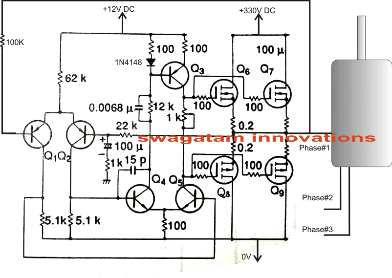
The circuit is basically a voltage amplifier which is able to amplify a source input voltage to the level that's applied across the mosfets.
Three identical circuits need to be built for implementing the proposed single phase to three phase converter circuit design idea.
Making an accurate three phase input source was difficult to design and implement therefore I thought of a rather unusual method of generating the required three phase input pattern.
Since normally the load at the output of the proposed design would be a three phase motor so initially this motor could be rotated manually such that it behaves like a three phase alternator generating the required initial sample three phase voltage for the amplifier input.
As shown in the circuit diagram, we need three such identical circuits connected with the three wires of the motor integrated with their outputs.
We can see that a feedback link from the mosfet output been applied to the input of the amplifier.
With the given conditions if the connected three phase motor is rotated at the specified frequency, a sample equivalent voltage/frequency would be fed back at the input.
This input would then get amplified and returned at the required high potential AC voltage to the motor, locking its rotation in that particular frequency, once this takes place the manual rotation could be stopped and hopefully the latching would sustain the influence as long as the 330V DC continues to exist across the mosfets.
The manual rotation of the connected three phase motor could be done through an external single phase motor coupled with the three phase motor using gears which could be detached by some suitable mechanism as soon the system gets latched.
Of course this is just an idea from my part, if there's any feasibility in this idea it can enhanced or improved through suitable modifications.
The left hand side driver section requires 12V DC which can be acquired via a standard AC/DC adapter while the mosfet supply can be obtained from a bridge rectifier network directly connected with the existing 220 or 120V single phase source.
Circuit Diagram
Devices required for the above single phase to three phase converter circuit.
Q1, Q2 = BC557,
Q3 = BD140
Q4, Q5 = BD139
Mosfets = 600V 1 amp, or approximate equivalent


Questions & Answers
what is the number of the mosfets
It will depend on the load’s power and current specifications.
Please i need a three phase control circuit for an AC 2.2kw water pump. The control will be able to stop the pump from operation whenever there is phase failure and also stop when the current is exceeded. (1.5A – 2.5A per phase)
How will the relays be triggered, i need more explanation. thanks
You have to press the push button to latch up the relays. If any one of the phase fails, all the 3 relays will turn off cutting off all the 3 phases to the load.
Thanks for the design, I’ve gone through the diagram and i want to ask what value of the transformers, the relays and the capacitors that will be used since the input is going through these components. As for the current i want to draw from the output, ie 2.5A. Am i going to base my calculations on the current i want to draw from the load?
For 2.5 amps, the relays can be the standard 5 pin 12V blue relays. The transformers can be 12v, 500 ma step down transformers. I am assuming each phase to be rated at 220v, so the transformer primary can be rated at 220v.
Will the 500mA transformer be able to carry the load of 2.5A per phase of the load? since the output is going to be connected to the output of the transformer? I need more clarification.
The transformer is only activating the relay, it has nothing to do with the load. The load is getting the 3 phase power directly from the input via the relay contacts.
Thanks for the clarification, I appreciate.
Hi, You can refer to the following post, it might help:
makingcircuits.com/blog/single-phase-preventer-circuit/
please give me detail connection for 1 phase 220v0lts converted to 3 phase 220 volts using idler motor to create 3rd phase with starting capacitor and running capacitors with timer relays and contactors. Thank you so much.
sir I am designing the inverter of single phase into 3 phase for 3 phase induction motor please help me in selecting the following things
1-N-channel mosfets of which type hexa bridge or 4 mosfets
2- gate trigging pwm,spwmor other
3-controller of which type
4-how to controle the speed of induction motor automatically
5-diode types for rectification
sir as soon as possible please it is final year project please
Hello Mehmood, here are the answers:
1) you will need six mosfet based full bridge for a 3 phase motor controller
2) gate triggering will need to be done from a specialized 3 phase IC
3) Controller should be as shown in htis example: https://www.homemade-circuits.com/universal-esc-circuit-for-bldc-motors/
4) Speed can be controlled automatically through a feedback network.
5) Diode specification will depend on the motoe power specification.
sir i am a broadcast engineer but at my free time i build inverters but i have not been able to get a better IGBT driver circuit a three phase driver circuits i need your help
Gideon, if you search online you will be able to find many options, here’s one of them:
https://www.homemade-circuits.com/compact-3-phase-igbt-driver-ic/
we are in solar PV power system. A house is having 5KWp connected load and it is having three phase connection from Electricity Company. Three phase solar inverter for 5KWp are not available from standard manufacturer. How could I use single phase inverter for three phase connection by electricity company. Can I use phase converter
you will have to modify the single phase inverter into a 3 phase inverter by adding a phase converter stage and power driver stages into it, externally nothing can be done to make this possible.
it has no 230V ac supply????????????
I have explained it in the article
sir,
how to adjust frequency?
Suresh, if possible i'll post the design soon in this blog…keep in touch.
Sir,
I'm doing single phase AC to DC full bridge controlled converter. The out put current is depend on the signal voltage 0-10V. Out put voltage is 100V. Please help me for circuit diagram.
Input supply. :230V AC
Signal voltage :0-10V
Output voltage :100V DC
Output current : 0-25A
the shown 330V is acquired after rectifying the 220V AC supply and is fed to the motor via the mosftes.