In this article I have explained how to design and build a solid state contactor circuit using triacs, with ON OFF push electronic switches, for operating heavy duty loads like submersible borewell pump motors with high reliability, and without any concerns about wear and tear issue or long term degradation issues of the contactor unit. It also includes a soft start circuit to ensure minimum switch ON surge and longer life for the motor.
What is a Contactor
A contactor is a form of mains operated ON/OFF switch, rated to handle heavy loads at high currents, and high switching spikes in the form arcs across their switching contacts.
It is mostly used for switching high wattage or high current inductive loads such as submersible 3 phase pump motors or other similar type of heavy industrial loads which may also include solenoids.
How a Contactor Works
A basic contactor switch will have the following basic elements in its electrical configuration:
In a standard mechanical contactor set up, the start switch which is a push-to-ON switch is used for latching the contactor contacts in a switched ON position so that the connected load is also switched ON, while the Stop switch which is a push-to-off switch is used to break this latch arrangement and to switch OFF the connected load.
When the push to ON switch is pressed by the user, an integrated electromagnetic coil is energized, which pulls a set of spring loaded heavy duty contacts and connects them hard with another set of heavy duty contacts. This joins the two adjoining sets of contacts allowing current to flow from the mains supply source to the load. The load is thus switched ON with this operation.
The electromagnetic coil and the associated sets of contacts form the relay mechanism of the contactor, which gets latched and switch ON each time the push-to-ON switch is pressed, or the START switch is pressed.
The Push-to-OFF switch acts in the opposite manner, when this switch is pressed, the relay latch is forced to break, which in turn releases and opens the contacts into its original switched OFF position. This causes the load to get switched OFF.
Problems with Mechanical Contactors
Mechanical contactors work quite efficiently through the above explained procedures, however in the long run they become prone to wear and tear due to heavy electrical arcing across their contacts.
These arcing are generally caused due to the masive initial current draw by the load which are mostly inductive by nature such as motors and solenoids.
The repeated arcing cause burning and corrosion on the contact surfaces which eventually become too degraded to work normally for the required switching of the load.
Designing an Electronic contactor
Finding an easy way to solve the wear and tear issue with the mechanical contactors looks daunting and complex, unless the design is entirely replaced with an electronic counterpart that would do everything as per the specs, yet be foolproof against mechanical degradation regardless how frequently these are operated and how big the load wattage may be.
After some thinking I could come up with the following simple solid state contactor circuit using triacs, and some other electronic components:
Circuit Diagram
Audio/Video Representation
Purpose Of Circuit
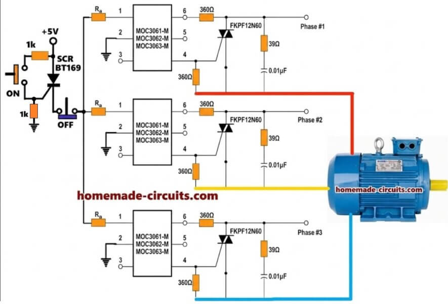
We are making here one solid state contactor circuit that can switch one 3 phase pump motor. We are not using big mechanical contactor but we are using opto isolator and triac.
So it becomes compact and noiseless.
Control Switch With SCR
We see at left side one small ON OFF latch. We use SCR BT169 for this.
So when we press ON push button then small current flows to gate of SCR and SCR becomes latched. Then +5V comes to supply line of opto isolator.
Now when we press OFF switch then latch of SCR breaks and supply cuts. So ON OFF action happens with very low current switch.
Opto Isolator Stage
We see MOC3061 or MOC3062 or MOC3063 used here. Inside this device there is one LED and one TRIAC driver.
So when +5V passes current through LED side then TRIAC driver inside becomes ON. Then it triggers gate of triac and triac becomes ON.
We use three such MOC306x because we have three phase. One for each phase.
Triac Switching Stage
We see triac FKPF12N60 used here. This is high voltage triac. It takes current from each phase and switches it to motor side.
There is 39 ohm resistor and 0.01uF capacitor connected across triac. This is snubber circuit. It stops spike and protects triac. So each phase has one triac and one snubber.
Motor Connection
The three output points Phase#1 Phase#2 Phase#3 go to motor input terminals.
So when SCR latch is ON then opto becomes active, triac becomes ON and motor gets all three phases.
Now when SCR latch is broken by OFF switch then opto becomes OFF, triac cuts supply and motor stops.
Step By Step Working
- We press ON → SCR latches → +5V goes to opto → opto drives triac→ motor runs.
- We press OFF → SCR unlatches → +5V cuts → opto stops → triac cuts → motor stops.
Why This Is Good
We are not using contactor so no spark, no wear, no sound.
We are using opto isolator so control side and motor side are isolated.
We get reliable, safe, compact solid state motor switch.
Adding a Soft Start to the above Design
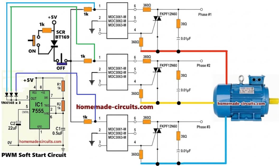
The above explained simple electronic start stop contactor for 3 phase motors can be further enhanced by adding a soft start feature as shown below, in order to reduce the initial switch ON current surge and also to safeguard the motor from initial high current stress.

Here, as we can see a IC 555 PWM generator is configured with the input LED terminals of the MOC opto couplers. As soon as the push to ON button is pressed, the opto couplers are triggered ON by the SCR, and simultaneously the IC 555 soft start PWM generator is also powered ON.
Now the IC 555 chops the LED current though its pin3 corresponding to the progressive PWM output at its pin3. This progressive PWMs are narrow and wide apart at the initial switch ON period, and gradually become closer and wider within a couple of seconds, causing the motor to start ON with higher chopped AC and lesser current and then after a couple of seconds the PWM progressively become wider allowing more current to the motor, until finally the PWMs turn into a pure DC, enabling full turn ON of the opto LEDs and allowing the motor to operate at its full normal speed.
Another Design But Looks Complex and is Unconfirmed
Another solid state 3 phase pump motor contactor circuit is discussed in the following sections, however this design looks rather complex and also I am not fully confident whether it will work correctly or not, so please proceed with caution.
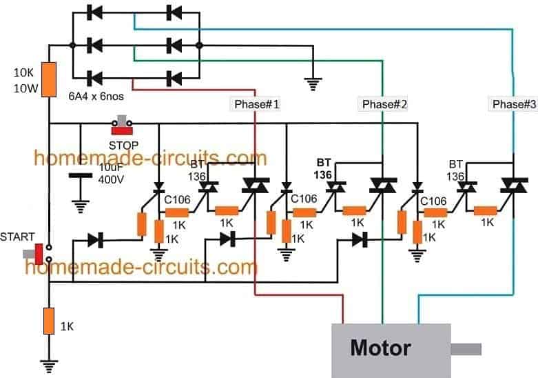
Parts List
All SCRs = C106 or BT151
All small triacs = BT136
All large triacs = BTA41/600
All SCR gate Diodes = 1N4007
All Bridge Rectifier Diodes = 1N4007
Circuit Operation
The design looks quite straightforward. We can see 3 high power triacs being used as switches for activating the 3 lines of the 3-phase input.
The gates of these high power control triacs are triggered by 3 attached low power triacs which are used as buffer stages.
Finally, the gates of these buffer triacs are triggered by 3 individual SCRs configured separately for each of these triac networks.
The SCRs in turn are triggered through separate push-to-ON and push-to-OFF switches to switch them ON and OFF respectively, this allows the triacs to be correspondingly triggered ON and OFF in response to the relevant push switch activation.
When the push-to-ON switch is pressed, all the SCRs become instantly latched, and this allows a gate drive to appear across the gates of all the 3 buffer triacs.
These triacs now start conducting, enabling gate triggering of the main power triacs, which finally begin conducting and allow the 3 phase power to reach the load, and the load is switched ON.
To stop this electronic contactor relay circuit, the push to OFF switch (STOP switch) is pressed by the user, which instantly breaks the latching of the SCRs, inhibiting the gate drive for the triacs and switching them OFF, along with the load.
Simplifying the Circuit
In the above diagram we can see intermediate triac buffer stages being used for relaying the triggering from the SCRs to the mains power triacs.
However a little examination reveals that, may be these buffer triacs could be eliminated, and the SCR output could be directly configured with the mains triacs.
This would simplify the design even further allowing only the SCRs stages to be used for the START and STOP actions and also reduce the overall cost of the unit.
Warning: The above circuit has not been confirmed practically. The author has designed this with his own understanding and knowledge.


Questions & Answers
I would like to know if there is a way to trigger this circuit with a soft start, or put a timer on the 5v to trigger the coupler gradually?
Sure, we can add a soft start circuit, in the following manner:
Hello, good afternoon, Mr. Swagatam. I have some questions about three-phase contactors. How can they be used for alternating current if a coil in alternating current would have to be vibrating? When a relay is powered by alternating current, it starts to vibrate. Why don’t contactors vibrate in alternating current? Thank you very much.
Hello, good afternoon, Mr. Swagatam. Thank you for your prompt reply. That was a really good explanation, very accurate and comprehensive. Thank you again.
Thank you Carlos, it is my pleasure!! Glad you found the explanation helpful!!
Hi Carlos, that’s a very good question, I will try to answer it:
In three phase or single phase AC contactors, they use one small copper ring on the iron core which we call shading coil. So when we put alternating current in the coil then the magnetic field also keeps changing direction again and again. Because of this, the main magnetic flux becomes zero for a very short time in every half cycle. So that time the armature should start vibrating or making noise.
But that does not happen, because the shading coil which is one copper ring on the pole face gets some induced current when the main flux keeps alternating. This induced current makes one more magnetic field which becomes little late or lagging compared to the main one. So even when the main flux becomes zero this small delayed flux from the shading coil still stays there for a short moment and keeps pulling the armature tightly.
Because of that lagging magnetic pull, the armature never gets free and it never vibrates or buzzes like the normal AC relay. We can say that the shading coil keeps some magnetic power always alive even at zero crossing, so the contactor stays pulled continuously and works smooth without any sound.
Sir I want to buy assambely kit what is the price
S.Singh, sorry, I do not have an assembled kit for this project…
شكرا جزيلا سيدى الكريم
على هذا التصميم والمشروع الرائع
وهو مفيد جدا بالتسبة لى
و بديل ممتاز عن مفتاح التحكم بالصغط الموجود فى محلات قطع غيار وتشغيل مواتير عليها حمل عالى
حيث أننى أسكن فى طابق عالى
وأرفع المياه لشقتى بواسطة موتور ٢حصان
وكثيرا ماينتج عن التشغيل المستمر تلف مفتاح التحكم بالضغط ،
حيث الموجود بمحلات قطع الغيار تتآكل نقط التوصيل خاصته
فى بضعة شهور
وبناء عليه سيكون المفتاح الموجود يتحكم بالضغط فقط والتوصيل سيتم عن طريق هذه الدائرة
شكرا جزيلا
سيدى الكريم
واسمح لى بمشاركة موقعكم الرائع
فى مجموعات الصيانة والإصلاح المشترك فيها
Thank you very much, dear sir
On this design and project
It is very useful for me
And an excellent alternative to the pressure control switch found in spare parts stores and running high-load motors
Where I live on a high floor
And raise the water to my apartment with a motor of 2 HP
Continuous operation often results in damage to the pressure control switch.
Where the spare parts stores are eroding their delivery points
in a few months
Accordingly, the existing switch will control the pressure only, and the connection will be made through this circuit
Thanks a lot
Dear sir
Allow me to share your wonderful site
In joint maintenance and repair groups
Thank you Mohamed, Glad you liked the article, I appreciate your thoughts.
Hello. Up to what engine power can this device be used?
Thanks in advance.
20 amp, 220V
Thank you so much.
Re all the points shown as earths on this diagram. Is this just a local electronic circuit earth? in my country this circuit is not to the AS3000 wiring code as shown if those points are connected to mains earth and if they were I think it would trip an rcd/earth leakage device. the snubber networks across the triacs asked about by another writer Niv B would be necessary too. (To control dvdt). A thermal overload would normally be used also between the contactor and the motor. (as Adonay asked about).
The “Earth” symbol in electronic schematics basically indicates the common negative DC line of the circuit, it is not related to the actual “earthing” or grounding connection with the mains earth or the soil, unless specified.
In my diagrams I only put the basic working concept of the project, I normally do not add all the minute details in it, I leave it on the users to add them, or rectify the issues through discussion in the comment section.
The many variants of the modern triacs today are snubberless, or have internal snubber, so it is recommended to use one of those snubberless triacs in this design, additionally one can add external snubbers also for extra safety.
https://www.mouser.in/datasheet/2/389/dm00747660-2042173.pdf
To control overheating a good heatsinking for the triacs is normally enough.
where is the power supply located?
the variable frequency drive circuitry you ask about is extremely complex. silicone chip magazine did a project on this though if you search
Hello, good morning everyone. I’m an electronics technician and I’m looking for a circuit for the control of ac motors up to 2 HP of power powered by only 1 phase and neutral, basically to power the compressor motor of air conditioners. Nowadays the air conditioning units are of the Inverter model, and have a circuit that actually controls the rotation of the motors and decreasing the rotation and the consumption of the air conditioning, this brings great energy savings. I know that these circuits are developed using IGBT transistors to control speed without losing torque. Would anyone have an electrical scheme to indicate? I am very grateful.
Fábio Lopes
Rio de Janeiro
Schematics shows a resistor between the SCRs’ gate diodes and the SCRs’ gates but its value is not provided, please advise.
Is there no need for a snubber circuit around the large triacs?
you can use 1k 1 watt for all the gate SCR/triac resistors
can this ssr be modified for single phase motors sir?
The above circuit is specifically designed to suit 3 phase motors, for single phase you can try this:
https://www.homemade-circuits.com/efficient-electronic-relay-ssr-circuit/
Hi,
I would like to know this is usually used in AC? If one want to use as a DC, is it possible to replace all the triacs with power FETs?
Hi, it is specifically for AC, using fets would require redesigning everything and might not be as easy as the above implementation
excuse my English
I have a doubt, I know that normally the triacs when damaged are shorted; so, if two of the triacs were short-circuited, when the engine is turned off it will be powered by two phases only and could burn. How could this be prevented?
on the other hand, it could happen that one of the triacs opened, and when the engine is started it will be powered only by two phases and could burn.
Thanks for your answer.
In that case you must add a single phasing preventor device with this circuit.
Can we use MOC3021 (SCR Output Opto-couplers) in place of C106 / BT151 ? so that we can operate it either manually or remotely through Arduino kind of controllers .
yes you can use it..
Can this circuit be modified for single phase 240 instead of 3 phase? And if so I presume that the neutral would be the ground connection shown in the circuit.
yes it can be done, as you have assumed…