An H-bridge is one very useful circuit arrangement which lets us reverse the polarity across a load, so now with one DC supply we can make current flow through the load in both directions alternately.
Because of that, these H-bridge circuits get used in many places like DC to AC inverter circuits, transformer drivers, bidirectional motor control, relay switching, solenoid driving, inductive loads and similar things where current direction has to reverse continuously.
Here we will see two simple versions, one using BJTs and another using MOSFETs. Nice thing here is both circuits work without any special driver ICs, just ordinary discrete parts, which keeps the design simple and easier to understand while building also.
Audio/Video Representation
1) Simple BJT H-Bridge Circuit
The first one is the BJT H-bridge circuit.
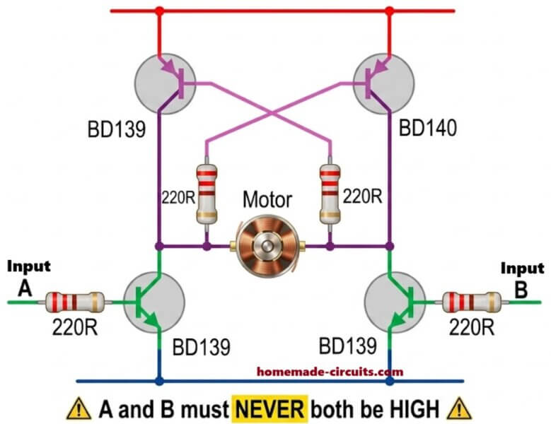
This design uses four complementary BJTs connected in the usual H-bridge form. Upper transistors are BD140 PNP types and lower transistors are BD139 NPN types.
Load is connected in the middle section of the bridge, which can be transformer primary, relay coil, lamp, small AC load, DC motor, solenoid or basically any bidirectional inductive load.
One interesting thing here is the crossed resistor connection between lower BD139 transistors and opposite side BD140 transistors. Because of this cross connection, diagonal switching happens automatically inside the bridge.
Circuit Operation
Suppose input A becomes HIGH while input B stays LOW, then left side BD139 turns ON through its 220 ohm resistor.
As it switches ON, collector voltage drops near ground level, and that low gets transferred through the crossed 220 ohm resistor into opposite side BD140 base.
Since BD140 is PNP type, pulling its base lower turns it ON.
So now one diagonal pair starts conducting, upper right BD140 and lower left BD139.
Current flows from positive rail through upper transistor, then load, then lower transistor and finally ground, so load current moves in one direction.
Now if input A goes LOW and input B becomes HIGH, then opposite diagonal pair conducts instead, upper left BD140 and lower right BD139, therefore current through load reverses.
If this switching keeps alternating continuously from an oscillator or similar stage, then load starts seeing alternating current from the DC source itself, which is why the bridge can work like a simple inverter stage.
Important Precaution
One thing however is very important here, inputs A and B should never become HIGH together.
If both become HIGH at same time then both lower transistors may conduct together and because of the cross coupling action upper transistors may also partly switch ON, so now supply rails can get directly shorted.
That condition can destroy transistors very quickly because current may rise heavily.
Therefore proper timing and little dead time becomes important in practical use.
Advantages of the BJT H-Bridge
This BJT version is simple, parts are easily available, no driver IC needed, troubleshooting also becomes easier. So for learning projects and lower power applications it works nicely.
Limitations
But BJTs have higher conduction loss compared to MOSFETs therefore at higher currents heating increases and efficiency falls. So bigger heatsinks become necessary. Because of that these BJT bridges are usually more suitable for lower and medium power range.
2) MOSFET H-Bridge Circuit
Now coming to the second design of MOSFET H-bridge version.
This one uses MOSFETs instead of BJTs, so efficiency becomes much better and current handling also improves a lot.
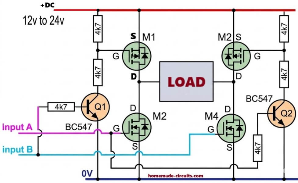
Here we have P-channel MOSFETs on high side and N-channel MOSFETs on low side.
Load again stays connected between bridge outputs.
Supply can be around 12V to 24V DC depending on MOSFET ratings and load requirement.
This design also works without dedicated driver ICs, which is another useful part of the circuit.
Ordinary BC547 transistors are used for driving the upper P-channel MOSFET gates.
Circuit Operation
Suppose input A becomes HIGH while input B remains LOW then transistor Q1 switches ON and pulls the gate of upper left P-channel MOSFET toward ground.
Since source of that MOSFET already sits at positive rail, so pulling gate lower creates the needed gate to source voltage difference and MOSFET switches ON.
At the same time input A also turns ON lower right N-channel MOSFET directly.
So now upper left P-channel MOSFET and lower right N-channel MOSFET become the conducting diagonal pair.
Current flows through load in one direction.
Then if input B becomes HIGH and input A goes LOW, then opposite diagonal pair conducts and load current reverses again.
If this alternating switching keeps repeating continuously at fixed frequency then AC like output appears across the load from the DC supply.
Function of the BC547 Transistors
Those BC547 transistors are mainly acting like small gate drivers for upper MOSFETs.
The 4k7 resistors connected to MOSFET gates work like pull up resistors, so normally MOSFETs remain OFF.
When BC547 switches ON then it quickly pulls MOSFET gate low and MOSFET turns fully ON.
So now expensive high side driver ICs are not needed here.
Advantages of the MOSFET H-Bridge
Compared to the BJT version, MOSFET bridge gives much higher efficiency, lower heating, faster switching and better power handling.
Because MOSFET ON resistance stays very low, so power loss becomes much smaller than BJTs which is why MOSFET H-bridges are much better for inverter systems and transformer driving work.
Important Safety Rule
One important safety thing again, inputs A and B must never become HIGH together.
If both sides conduct together then shoot through current can happen, where supply gets almost directly shorted through the bridge itself and components may fail very fast.
So proper timing and dead time control always matters in H-bridge circuits.
Final Thoughts
Both these H-bridge designs are simple ways for creating bidirectional current flow through a load using only discrete parts.
The BJT version is good for learning and smaller applications, while MOSFET version is much better for practical inverter use because heating stays lower and efficiency remains higher.
Best thing is both circuits avoid specialized driver ICs, so parts stay economical, building becomes simpler, and modifications also become easier depending on the application.


Questions & Answers
can you tell me if in the simple h-bridge the extra resistors (in the youtube video) are pullup/pulldown resistors?
The video shows the same diagrams which are also shown in the above article…which diagram and which resistors are you referring to??
in the video on you tube at 0:34 under two simple h-bridge design, on the left the pcb board of the simple h-bridge with bjts, there are more resistors then the diagram of the web site, so I am referring to those extra resistors
Please don’t see the PCB images those are just symbolic images…the circuit diagrams are the real ones…