The proposed variable drill speed controller circuit maintains a constant (adjustable) speed over the drill machine motor, regardless of the load.
One of the most used power tools is the power drill machine. Despite its innumerable advantages, the power drill has one major setback – constant high speed for many applications.
Even when there are dual-speed configurations, the lower limit covers around 300-750 rpm, which is still very fast for subtle jobs like drilling masonry or utilizing fly-cutters on sheet metal.
Our version of the speed controller in the power drill permits variation of speeds from 0 to 75% of full speed. Moreover, it also allows for normal speed operation without detaching the controller from the drill.
Even when there are changes in load, the controller is equipped with built-in compensation to preserve the considerably uniform speeds.
How it works
The typical characteristic of an electric motor is that it produces a reverse voltage that opposes the supply when running.
This condition is called the back EMF. The opposing voltage is found to be proportional to the speed of the electric motor. The SCR drill speed controller utilized this effect to deliver a definite amount of speed-versus-load compensation.
This controller deploys a Silicon Controlled Rectifier (SCR) to gate half-wave power to the drill motor. The fundamentals of the conductivity of an SCR are:
- The anode (terminal A) has a positive charge with respect to the cathode (terminal K).
- When the gate (terminal G) develops at least 0.6 V positive with respect to the cathode.
- Around 10 mA of current is flowing into the gate terminal.
The time at which the SCR switches on in each positive half cycle can be efficiently regulated by controlling the level of voltage waveform to the gate. In conclusion, we can perfectly control the amount of power supplied to the drill.
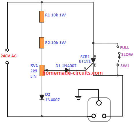
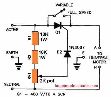
Resistors R1 and R2, and potentiometer RV1 become a voltage divider that provides a half-wave voltage of adjustable value to the SCR’s gate. If the motor is motionless, the cathode of the SCR will be at 0 V and it will almost completely turn on. As the speed of drill elevates, a voltage forms across the drill.
This additional potential reduces the effective gate-cathode voltages. So, when the motor accelerates, the power supplied decreases until the motor becomes stable at a speed regulated by the configuration of RV1.
Let’s say a load is placed on the drill. This will tend to decelerate the drill and simultaneously causes the voltage across the drill to drop. Then, more power will is supplied to the motor because of the automatically advanced firing-time of the SCR.
Therefore, the drill speed is maintained once set regardless of load. Diode D2 functions to halve the power dissipated in R1, R2 and RV1 by means of restricting the current through them to positive half-cycles only.
Diode D1 safeguards the SCR gate from extreme reverse voltage.
SW1 easily shorts out the SCR in the full speed position. As a result, RV1 does not work and the whole mains supply is applied to the drill.
Construction
Most importantly, it is crucial to know that the drill speed controller circuit is directly connected to the mains without an isolating transformer.
Therefore, precautionary measures must be taken during the assembly so that no severe or fatal injury occurs.
The use of a tag strip or a PCB is not required because only a handful of electronic components are utilized. Only two “mid-air” joints are necessary and these must be securely insulated to avoid any chance of short circuits.
A stud-mounting type of SCR is used for this project. This component is placed using the solder lug that comes with it and soldered onto the centre lug of the switch.
There are no heatsinks necessary for loads up to 3 A. If you have a plastic-pack SCR, you may drill a hole through the switch lug and bolt the SCR straight.
Nevertheless, it is recommended that a piece of aluminium, with a dimension of 25 mm x 15 mm, be placed between the SCR and switch lug to function as a heatsink.
It is fundamental to remember to make earth connections for all external components because the unit is operating at 240 Vac. For the case, we employed a plastic compartment with a metal lid.
Furthermore, a cable clamp attached with a metal screw through the side of the plastic case is used.
Remember to prepare the earth connection for this screw, the lid and the earth terminal of the output socket.
It is essential to use only continuous wiring as earth cables go from one earth point to another without intermediate links. It is okay to solder two earth cables to one earth lug but never fasten two wires under a single screw.
The aluminium cover on the UB3 box is not robust for this application particularly when the hole for the output socket is cut.
Therefore, ensure to fabricate a new lid from an 18 gauge steel or 16 gauge aluminium material.
As an added safety precaution, it is recommended to use a small amount of glue, lacquer or even nail polish on the grooves of the screw that will be secured inside the unit. This guarantees secure fitting.
You may notice on some SCR’s, the trigger current provided by R1 and R2 is inadequate. To overcome this, just add an extra 10k resistor in parallel with each resistor.
How to Use
Firstly, attach the drill speed controller circuit to the mains supply and the drill into the controller.
Then, select the speed you desire – full or variable speed. You may notice there is no ON or OFF switch because the toggling function is provided by the drill’s switch itself.
At full speed, the drill runs normally and the speed control on the controller has zero effect.
If variable speed is selected, the control will regulate the speed between 0 and 75% of full speed. It is possible that there are dead zones at low speed and high speed ends of the control.
This is very normal and it happens because of the drill properties and component tolerances within the controller.
At extremely low speeds, you may notice the drill jerks under no load. But the moment a load is introduced, the jerk is reduced and eventually disappears.
As long as the drill is utilized at less than full speed, the cooling effect of the motor will be significantly reduced.
This happens because the cooling fan is attached on the armature shaft and also spins slower. Therefore, the drill will become hotter when used at low speeds, so it is important not to use the drill in this mode for a long period.
- PARTS LIST
- R1,R2 = Resistor 10k 1W 5%
- RV1 = Potentiometer 2.5k Lin
- D1,D2 = Diodes 1N4004
- SCR1 = SCR 2N4443 or BT151 (8A/10A, 400V)
- SW1 = Switch Box
- 3 -core flex and plug
- Cable clamp
- 3 -pin power outlet
You may find some SCR's having triggering current over normal value, which may inhibit the units operation. In such cases you can add SCRs in parallel, along with the two 10k resistor with additional 10k resistor to ensure that sufficient current is available for the SCR gate triggering.
Another SCR based Drill Speed Controller Circuit
With something like a variable-speed electric drill, it is frequently simpler to drill holes in various kinds of metals, plastic, etc.
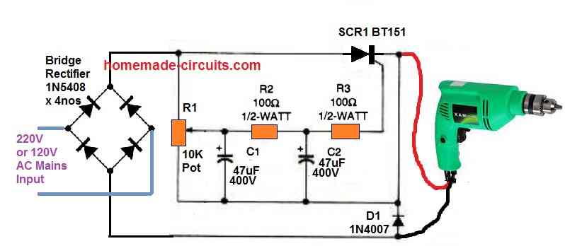
If, like me, you do not have a multi-speed drill, you may upgrade a single-speed drill to be more helpful by adding the small circuit indicated in the above image.
The SCR1 switch's full-wave pulsating direct current is provided by the bridge rectifier (BR1). While SCR1 must have a PIV of 300V and a current rating of 25A, the bridge rectifier must be rated at 500 PIV and have a current rating of 10A.
The drill motor's reverse voltage is countered by diode D1, which has a 2A rating. R1 adjusts the speed of the drill. Furthermore, you can consider using a soldering iron with the circuit for the testing purpose.
Using Triac Phase Control
Almost all drill speed controllers are afflicted with several negative aspects. For instance , inadequate speed stability, too much shakiness at reduced speeds, and large power dissipation from the series resistor employed to detect the motor current.
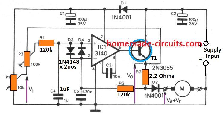
The circuit I have explained in this article includes nothing of these disadvantages, and moreover is incredibly simple. The mains AC input is rectified by D1 and lowered by R1.
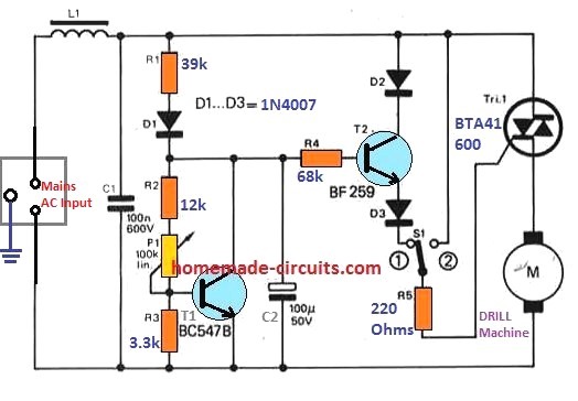
The current consumed by T1 could he governed through P1, therefore also manipulating the DC voltage which presents itself across C2, thus at the T2 base.
T2 is hooked up as an emitter follower, and the voltage developing in the cathode of D3 is around l.5 V below the T2 base voltage.
Supposing that the motor is switching but that the triac is powered down, the back e.m.f. created through the motor will develop on the T1 pin of the triac.
As long as this voltage is higher than the D3 cathode voltage, the triac will stay switched off, however as the motor decelerates this voltage will drop and the triac will activate.
In the event the loading on the motor rises, as a result causing the drill motor to slow down, the back e.m.f. will drop faster and the triac will trigger more rapidly, as a result causing the motor back up to increase in speed.
Because the triac could be activated only on positive half-cycles of the AC waveform the drill speed controller is not going to adjust the motor speed continually from zero to throttling speed, and for standard full-speed working S1 is incorporated, which activates the trlac on entirely.
Nevertheless, the circuit shows very good speed control attributes across the crucial reduced speed range. L1 and C1 deliver r.f. interference suppression caused by the triac phase chopping.
L1 could be a over the counter readily available r.f. suppressor choke of a several microhenries inductance.
The current rating of L1 must be between two to four amps, with respect to the current rating of the drill motor. Just about any 600V 6 A triac will work extremely well in the circuit.
500 Watt Drill Speed Controller Circuit
Electric drills are driven by a universal motor that allows for speed adjustment by altering the portion or phase of the electrical cycle during which the triac, Q2, conducts.
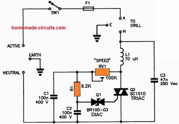
This uncomplicated phase control circuit offers a broad range of speed adjustments, and the motor's back electromotive force (back-emf) offers feedback to advance the phase when the motor encounters a load.
This circuit is designed to control drills with a power rating of up to 500 VA. It's recommended to mount Q2 on a small heatsink, and F1 is a 4 A fuse, while L1 is a high-current choke.
Another SCR based Drill Machine Speed Controller Circuit
This uncomplicated motor speed controller effectively manages the slow-speed operation of universal electric motors, especially those found in drill machines.
Even in the case of two-speed drill machines, the low-speed setting can often be excessively rapid for certain tasks, such as drilling through sheet metal.
This circuit is noteworthy for its minimal component count and offers a speed variation of up to 75 percent of the motor's highest achievable speed. Utilizing the provided switch allows for full-speed operation.
The resistive divider and D1 collaborate to generate half-wave pulses with adjustable amplitude, which are subsequently applied to the gate of the SCR, designated as Q1.
Initially, presuming the motor is at rest, the SCR's cathode remains at a zero-voltage state, causing the SCR to trigger upon the first positive half-wave from the mains.
As the motor commences its operation, the voltage across it decreases, consequently reducing the gate-cathode voltage of the SCR.
This results in reduced power supplied to the motor until it stabilizes at a speed dictated by the adjustment of RV1.
When the motor encounters a load and begins to decelerate, the voltage across the motor decreases as well.
However, the SCR's firing timing during each cycle advances, delivering more power to the motor. This offsets the load on the motor, allowing it to uphold a consistent speed.
Once the speed is established, it remains relatively unwavering, notwithstanding fluctuations in the motor's load.
Diode D1 functions as a protective barrier for the SCR gate against excessive reverse voltage, which could potentially harm the SCR.
It is essential to emphasize that the SCR used should possess a gate sensitivity that is comparatively high. If additional gate current is necessary for effective SCR triggering, it is possible to reduce the values of both R1 and R2 to 4.7k each.


Questions & Answers
Hi Swagatam. thank for your excellent website. My question is this . I would like to create a way of controlling the speed of an 240 VAC motor ,specifically a sewing machine motor .Where the physical control by the operator is generated by air pressure . This pressure is then converted to a signal by a pressure transducer. Which in turn is used to activate circuitry controlling the speed of the motor. My main questions are: how do I use the signal produced by the transducer to control the motor speed . Also in most standard sewing machine foot controls use a micro switch to control the power to the speed control circuit . This is usually activated by the users foot pressure in the initial few millimeters of travel of the pedal of a standard sewing machine controller pedal. Is there a way of using to initial signal from the transducer to activate a switch like device (reed switch possibly?) to replace the micro switch or a way of omitting it altogether?
Thank you Alasdair,
This can be perhaps done using a force sensor resistor and a PWM controller circuit. I will try to design the circuit soon and let you know.
Hi Swagatam, I didn’t express myself clearly and I missed some important component information out. My apologies. Here is a link to the pneumatic control I wish to use https://presair.com/pneumatic-controls-medical-devices/ . I would like to couple it with a MPS20N0040D-D https://electropeak.com/pressure-meter-mps20n0040d which could work with your proposal of a PWM controller circuit. The output voltage of the transducer is 50-100 Mv . Would this need to be amplified before passing it to a PWM controller circuit? Thanks for your help.
Hi Alasdair,
You can perhaps try implementing the following circuits by integrating them together, and check how they respond:
Many thanks . I’ll try this out. Some questions, on the second diagram there is a component number 1N40 that does not appear to be connected into the circuit. Is this correct? Is it possible to add a rectification circuit to supply both the 12v required by the 555 and the 5v required by the amplifier circuit from the mains supply ?
Please ignore the 1N70 misprint, actually in the original diagram the motor was a DC motor with a 1N4007 diode connected across it, and I forgot to erase the 1N4007 fully.
You can use 12V for both the circuits and yes it will need to be supplied from a AC to DC adapter.
The first op amp circuit was taken from internet, the second 555 circuit is my circuit…
Hi Swagatam, thanks for the clarification and your generosity in sharing your ideas. I will build the circuits and see how it goes , I’ll let you know via the comments
That’s great Alasdair, all the best to you!
Hi Swagatam, a couple more questions. The original foot controller has two connections that connect it to the sewing machine .Could you help me understand where to place these two connections from the machine to the 555 circuit to replace the effect of the original foot pedal? Also could you help me understand the role of the 4 IN5408 diodes in the 555 circuit . Thanks for your patience .
Hi Alasdair,
Unfortunately I cannot help with the foot controller integration, since i do not have any idea regarding its working or construction.
I can only help you with the functioning of the circuit.
The 4 diodes convert the AC into DC for the MOSFET to work with the AC motor.
Could you use a bridge rectifier on the AC input to allow operation on the negative going part of the cycle?
That is a very wise solution!
You may have explained and I missed it, but a lot of the neat schematics you provide reference a power source of 240vac, just wondering why, rather than 120vac. Have a fine day. Ron
You can use 120 V in place of 240 V if you are in a country that works with 120 V AC outlets. The “input supply” basically suggests the use of mains AC from the grid, it may be 240V or 120V depending of the country specs.
Will it work even if the motor from my drill press has a start capacitor?
Yes it will work for capacitor start motors.