• Skip to main content
  • Skip to primary sidebar

Homemade Circuit Projects

Need circuit help? Post them in the comments! I've answered over 50,000!

Blog | Categories | About | Contact | Calculators-online
You are here: Home / Motor Controller / RPM Controller Circuit for Diesel Generators

RPM Controller Circuit for Diesel Generators

Last Updated on July 6, 2019 by Swagatam 19 Comments

In this post I have explained a diesel generator RPM controller circuit for boats using PWM technique and also using a simple triac shunt circuit. The idea was requested by Mr. Dave.

Table of Contents
  • The Design
  • Using the Triac Shunt Method

Circuit Objectives and Requirements

  1. I have been looking with interest at your electronic circuits web site and would appreciate it you could comment on the following
  2. I presently run a 220v 50 hz generator from the main diesel engine in my boat, the RPM of this engine is NOT governed and is difficult to set at the correct rev to keep the generator at the correct RPM for 50 hz output
  3. Would it be possible to convert this varying AC FREQUENCY 220V to 220v dc using a bridge rectifier and then convert it back to 220 v olts 50hz
  4. This would solve a major problem for those of us that have small boats that do not have space or are able to carry the extra load of another marine diesel engine, the generator is capable of 4kva output
  5. Your comments would be appreciated

The Design

The requested circuit deign for controlling a diesel generator RPM can be executed either by employing a PWM technique or the same could be implemented through an automatic shunt regulator circuit design, I have explained the two counterparts from the following explanation:
Diesel Generator RPM Controller Circuit

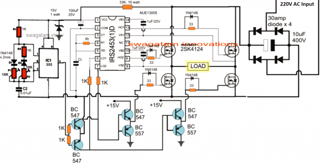
The first idea as indicated above employs an IRS2453 full bridge inverter circuit and an attached IC 555 PWM controller stage for the intended RPM control of a diesel generator output.

The design looks pretty straightforward, wherein the diode bridge network converts the 220V input to a 330V DC bus voltage for the full bridge driver network, which in turn converts it into a 220V AC square wave through the associated 4 N-channel push pull mosfet network.
Since this output is 330V DC square wave output, it is appropriately processed using the IC 555 PWM section into the required 220V AC sine wave output.The PWM setting ensures a fixed 220V output which can e expected to be relatively stble without fluctuations.

Using the Triac Shunt Method

Although precise, the above concept looks quite elaborate and complex when compared to the following simple triac shunt based diesel generator controller circuit:

vawt 1

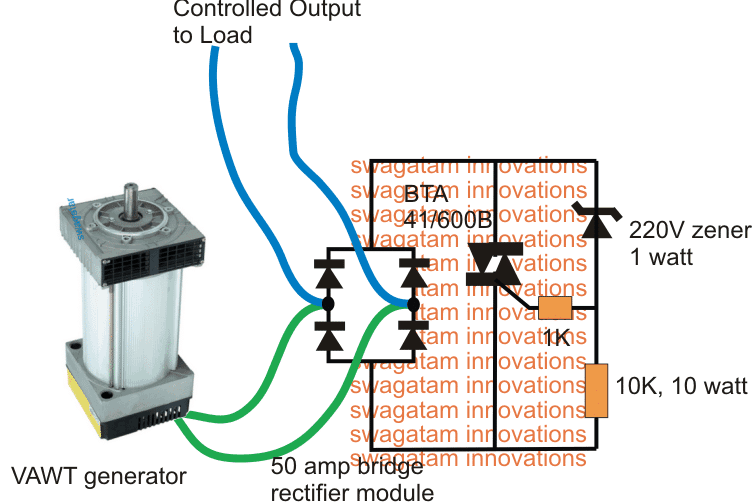
The above circuit was originally designed for controlling a windmill VAWT motor

However the same design could be also effectively used for controlling a diesel generator output to a fixed 220V.
The circuit looks much simpler and self explanatory.
The bridge rectifier converts both the half cycles from the diesel generator into positive full wave cycles for the triac, so that the triac circuit is able to shunt both these cycles to ground that may exceed the 220V mark.

The 220v zener diode fixes the shunting level for the triac, this section could be replaced using TL431 shunt zener IC for enabling an accurate temperature stabilized output for the generator.The bridge network must be adequately rated to handle the generator current peaks.

You'll also like:

  • 1.  How Brushless DC (BLDC) Motors Work
  • 2.  Bluetooth Motor Controller Circuit
  • 3.  How to Make a 3 Phase VFD Circuit
  • 4.  Constant Torque Motor Speed Controller Circuit
  • 5.  Push Button Fan Regulator Circuit with Display
  • 6.  Washing Machine Motor Agitator Timer Circuit

About Swagatam

I am an electronics engineer with over 15 years of hands-on experience. I am passionate about inventing, designing electronic circuits and PCBs, and helping hobbyists bring their projects to life. That is why I founded homemade-circuits.com, a website where I share innovative circuit ideas and tutorials. Have a circuit related question? Leave a comment.... I guarantee a reply!

Previous Post: « Calculating Capacitor Charge/Discharge Time using RC Constant
Next Post: Battery Charger Circuit using Fixed Resistors »

Reader Interactions

Comments

  1. Aref says

    March 28, 2023 at 4:35 pm

    What are ct and rt values?

    Reply
    • Swagatam says

      March 28, 2023 at 5:14 pm

      You will have fix them practically using a frequency meter.

      Reply
      • Aref says

        March 28, 2023 at 6:57 pm

        thanks

        Reply
  2. Aref says

    March 28, 2023 at 4:34 pm

    What is the role of MJE13005 in the schematic, please?

    Reply
    • Swagatam says

      March 28, 2023 at 5:12 pm

      Please ignore it….it is mistakenly shown there.

      Reply
  3. Aref says

    March 28, 2023 at 12:24 am

    Very good plan. thank you.
    what is the acceptable range for +15vdc?
    thanks

    Reply
    • Aref says

      March 28, 2023 at 10:46 am

      Is +12vdc ok?

      Reply
      • Swagatam says

        March 28, 2023 at 12:05 pm

        Yes, 12V can be used for operating the driver section.

        Reply
  4. Slavva says

    October 13, 2021 at 7:45 pm

    the simplest way to convert generator’s AC to stabilize voltage with exactly=50Hz it to buy a VFD-vario frequency drive or of any another similar product from any another country.
    Single phase generator’s power will be given to A and B input-phases of the VFD with a loads – to exit of the VFD. Than – to program the VFD properly=according to the user’s needs – the programming can be behind of usual application’s but within of physical possibilities of the VFD. Details of the programming depends on the VFD model.

    Reply
  5. Michael Ihekwereme says

    September 24, 2021 at 11:32 pm

    what is the “load” in the h bridge configuration

    Reply
    • Swagatam says

      September 25, 2021 at 8:44 am

      any electrical appliance

      Reply
  6. Enrique says

    October 16, 2019 at 6:20 am

    Good morning, excellent material that I find on the site, I congratulate you

    Please I would like to know more about IGBT, if possible more content with control circuits and practical applications, such as sine wave inverters
    Thank you

    Reply
    • Swagatam says

      October 17, 2019 at 9:49 am

      Glad you liked it! Using IGBTs is not complex. You can apply any voltage between 2 to 12V to switch them ON, while the load must be within the rated limits or the specifications of the device.

      The base does not require a resistor unlike BJTs since IGBTs have high niput impedance, like MOSFeTs

      Reply
      • Enrique says

        October 17, 2019 at 8:28 pm

        Ok muchas gracias, y estoy atento a nuevas publicaciones

        Reply
  7. ABHISHEK Gupta says

    March 17, 2018 at 2:19 pm

    Above comment for three phase inverter

    Reply
    • Swagatam says

      March 17, 2018 at 4:28 pm

      please post your question under the 3 phase inverter article

      Reply
  8. ABHISHEK Gupta says

    March 17, 2018 at 2:17 pm

    I’m give the output of LM 324 to mosfet which drive the led.but not drive the transformer for voltage up
    Sir. What I do

    Reply
    • Swagatam says

      March 17, 2018 at 4:27 pm

      sorry, I could not understand your question, which circuit are you referring to?

      Reply
  9. Killtan Roy says

    December 29, 2016 at 6:37 am

    nice

    Reply

Need Help? Please Leave a Comment! We value your input—Kindly keep it relevant to the above topic! Cancel reply

Your email address will not be published. Required fields are marked *

Primary Sidebar

Subscribe to New Circuit Ideas

Categories

  • Arduino Projects (87)
  • Audio and Amplifier Projects (132)
  • Automation Projects (17)
  • Automobile Electronics (101)
  • Battery Charger Circuits (83)
  • Datasheets and Components (104)
  • Electronics Theory (143)
  • Free Energy (37)
  • Games and Sports Projects (11)
  • Grid and 3-Phase (19)
  • Health related Projects (25)
  • Home Electrical Circuits (12)
  • Indicator Circuits (14)
  • Inverter Circuits (87)
  • Lamps and Lights (142)
  • Meters and Testers (69)
  • Mini Projects (46)
  • Motor Controller (64)
  • Oscillator Circuits (27)
  • Pets and Pests (15)
  • Power Supply Circuits (108)
  • Remote Control Circuits (50)
  • Security and Alarm (64)
  • Sensors and Detectors (101)
  • Solar Controller Circuits (59)
  • Temperature Controllers (42)
  • Timer and Delay Relay (49)
  • Transmitter Circuits (29)
  • Voltage Control and Protection (37)
  • Water Controller (36)

Calculators

  • Battery Back up Time Calculator
  • Capacitance Reactance Calculator
  • IC 555 Astable Calculator
  • IC 555 Monostable Calculator
  • Inductance Calculator
  • LC Resonance Calculator
  • LM317, LM338, LM396 Calculator
  • Ohm’s Law Calculator
  • Phase Angle Phase Shift Calculator
  • Power Factor (PF) Calculator
  • Reactance Calculator
  • Transistor Astable Calculator
  • Transistor base Resistor Calculator
  • Voltage Divider Calculator
  • Wire Current Calculator
  • Zener Diode Calculator
  • Filter Capacitor Calculator
  • Buck Converter Calculator
  • Boost Converter Calculator
  • Solar Panel, Inverter, Battery Calculator
  • Wire Current Calculator
  • SMPS Transformer Calculator
  • IC SG3525, SG3524 Calculator
  • Inverter LC Filter Calculator

People Also Search

555 Circuits | 741 Circuits | LM324 Circuits | LM338 Circuits | 4017 Circuits | Ultrasonic Projects | SMPS Projects | Christmas Projects | MOSFETs | Radio Circuits | Laser Circuits | PIR Projects |

Recent Comments

  • Swagatam on EGS002 Datasheet, Circuit Diagram Explained
  • Swagatam on How to Make IC LM339 Circuits
  • Swagatam on How to Make Dog Barking Preventer Circuit using High Frequency Deterrence
  • Swagatam on How to Buy and Use RF Remote Control Modules – Control Any Electrical Gadget Remotely
  • Swagatam on How to Generate PWM Using IC 555 (2 Methods Explored)

Company

  • Privacy Policy
  • Cookie Policy
  • About Me
  • Contact
  • Disclaimer
  • Copyright
  • Videos
  • Sitemap

Social Profiles

  • Twitter
  • YouTube
  • Instagram
  • Pinterest
  • My Facebook-Page
  • Quora
  • Stack Exchange
  • Linkedin
  • © 2025 · Swagatam Innovations