In this project we are going learn how to make a simple unipolar stepper motor driver circuit using 555 timer IC. Apart from 555 timer we also need IC CD 4017 which is a decade counter IC.
By Ankit Negi
Any unipolar motor can be connected to this circuit for performing specific task, though you need to do some small changes first.
Speed of the stepper motor can be controlled from a potentiometer connected between discharge and threshold pin of 555 timer.
Stepper Motor Basics
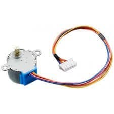
Stepper motors are used in areas where a specific amount of rotation is required, not achievable using ordinary d.c motors. A typical application of stepper motor is in a 3D PRINTER. You will find two types of popular stepper motor: UNIPOLAR and BIPOLAR.
As the name suggests unipolar stepper motor contains windings with common wire which can be easily energized one by one.
Whereas bipolar stepper motor does not have a common terminal between coils due to which it cannot be driven simply by using the proposed circuit. To drive bipolar stepper motor we need an h-bridge circuit.
COMPONENTS:
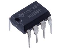
1. 555 TIMER IC
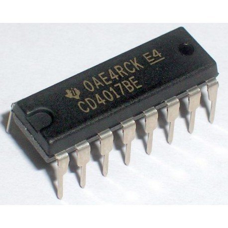
2. CD 4017 IC
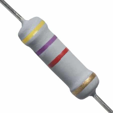
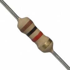
3. RESISTORS 4.7K, 1K
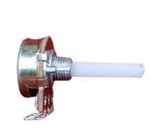
4. POTENTIOMETER 220K
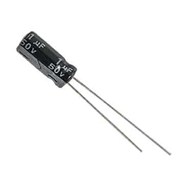
5. 1 uf CAPACITOR
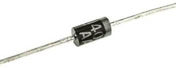
6. 4 DIODES 1N4007
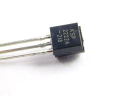
7. 4 TRANSISTORS 2N2222
8. UNIPOLAR STEPPER MOTOR
9. DC POWER SOURCE
PURPOSE OF 555 TIMER:
555 timer is required here to generate clock pulses of particular frequency (can be varied using 220k pot) which determines the speed of the stepper motor.
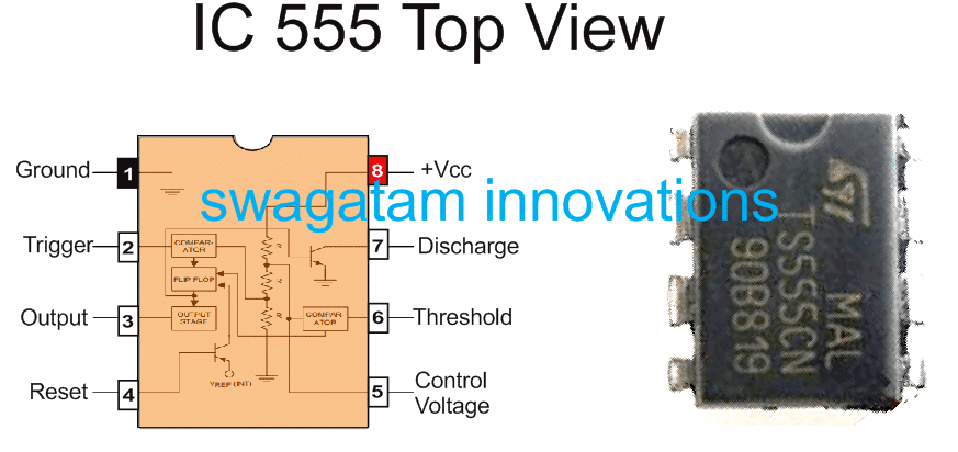
IC 555 Pinout details
PURPOSE OF CD4017:
As already mentioned above, it is a decade counter IC i.e., it can count up to 10 clock pulses. What make this IC special is that it has its own inbuilt decoder. Due to which you do not have to add an additional IC to decode binary numbers.
4017 counts up to 10 clock pulses from 555 timer and gives high output corresponding to each clock pulse one by one from its 10 output pins. At a time only one pin is high.
PURPOSE OF TRANSISTORS:
There are two purposes of transistor here:
1. Transistors act like switches here, thus energizing one coil at a time.
2. Transistors enable high current to pass through them and then motor, thus excluding 555 timer completely as it can supply very little amount of current.
CIRCUIT DIAGRAM:
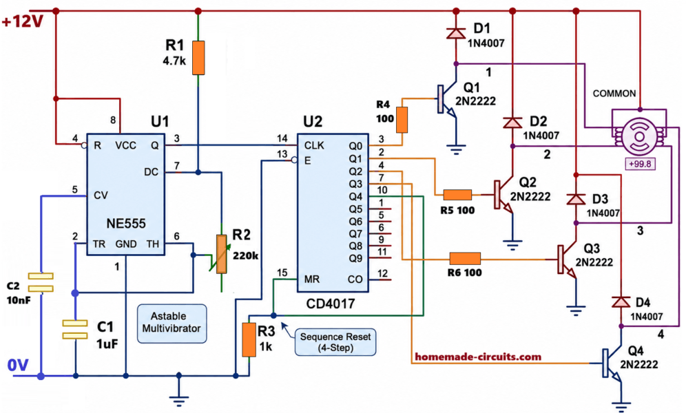
Make connections as shown in figure.
1. Connect pin 3 or output pin of 555 timer to pin 14 (clock pin ) of IC 4017.
2. Connect enable pin or 13th pin of 4017 to ground.
3. Connect pins 3,2,4,7 one by one to transistors 1,2,3,4 respectively.
4. Connect 10 and 15th pin to ground through a 1k resistor.
5. Connect common wire of stepper motor to the positive of supply.
6. Connect other wires of stepper motor in such a way so that coils are energized one by one to complete one full revolution properly.( you can look into datasheet of the motor provided by the manufacturer)
WHY OUTPUT PIN 10 OF IC 4017 IS CONNECTED TO ITS PIN 15 (RESET PIN)?
As already mentioned above 4017 counts clock pulses one by one up to 10th clock pulse and gives high output on output pins accordingly, each output pin goes high.
This causes certain delay in rotation of motor which is unnecessary. As we require only first four pins for one complete revolution of motor or first four decimal counts from o to 3, pin no. 10 is connected to pin15 so that after 4rth count IC resets and counting starts from the beginning again. This ensures no interruption in the motor’s rotation.
WORKING:
After making connections properly if you switch on the circuit motor will start rotating in steps. 555 timer produces clock pulses depending on the values of resistor, potentiometer and capacitor.
If you change value of any of these three component frequency of clock pulse will change.
These clock pulses are given to IC CD 4017 which then counts the clock pulses one by one and give 1 as output to pin no 3,2,4,7 respectively and repeats this process continuously.
Since transistor Q1 is connected to pin 3, it switches on first then transistor Q2 followed by Q3 and Q4. But when one transistor is on all other remain off.
When Q1 is on it acts like a closed switch and current flows through common wire to wire 1 and then to ground through transistor Q1.
This energizes coil 1 and motor rotates at some angle which depends on clock frequency. Then same thing happens with Q2 which energizes coil 2 followed by coil 3 and coil 4. Thus one complete revolution is obtained.
When potentiometer is rotated:
Let’s say initially position of pot is such that there is maximum resistance (220k) between discharge and threshold pin. Formula for frequency of output clock pulse is :
F = 1.44/(R1 + 2R2)C1
It is clear from the formula that frequency of clock pulses decreases as value of R2 increases. Thus when R2 or pot’s value is maximum, frequency is minimum due to which IC 4017 counts more slowly and gives more delayed output.
As value of resistance R2 decreases, frequency increases which causes minimum delay between outputs of IC 4017. And hence stepper motor rotates faster.
Thus value of potentiometer determines speed of the stepper motor.
SIMULATION VIDEO:
Here you can clearly see how speed of the motor varies with resistance R2. Its value is first decreased and then increased which in turn first increases and then decreases speed of the stepper motor.
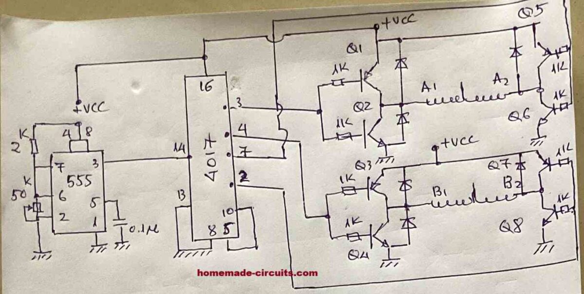
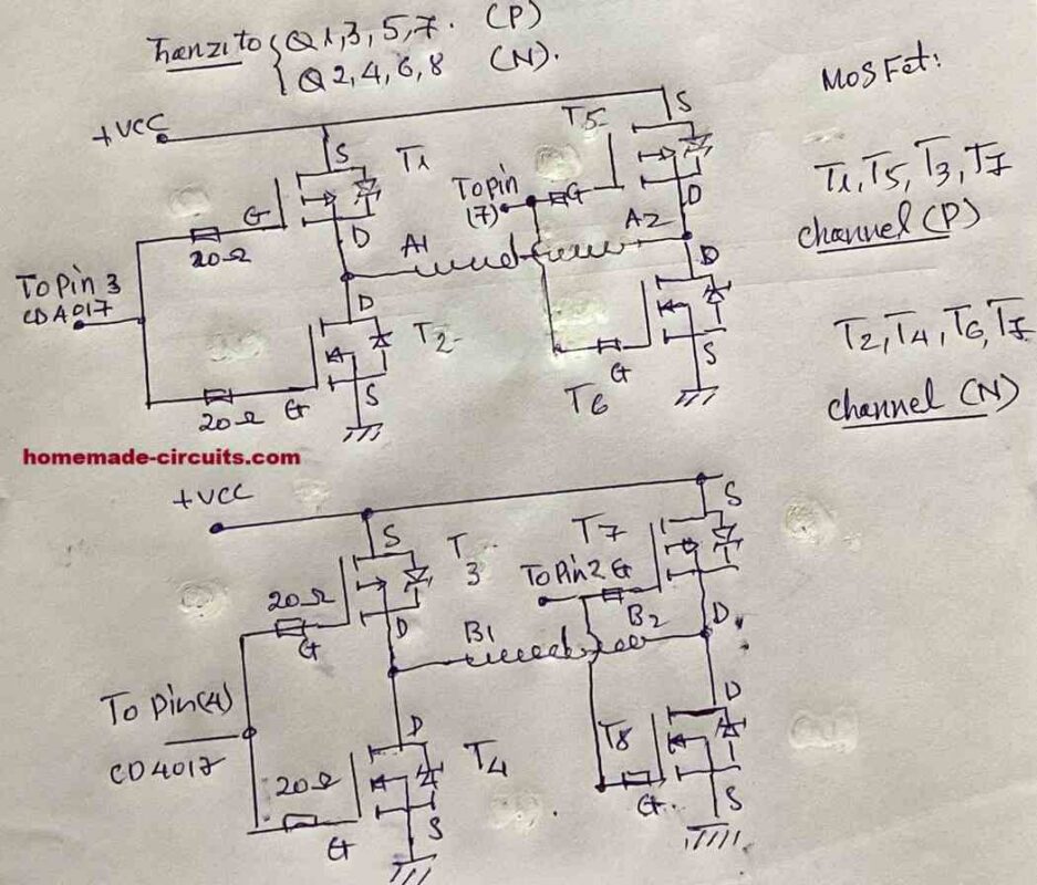
Stepper Motor Driver Circuit using BJT and MOSFET H-Bridge Configuration
The following diagram was drawn and contributed by Mr. Thiệu, who is a dedicated reader of this blog and an avid electronic enthusiast. I am thankful to him for his kind contribution to this blog.
The complete circuit diagram for the stepper motor driver using IC 555, IC 4017 and MOSFET H-bridge is shown in the following figure.


Questions & Answers
Hi Swagatam,
I have built the Flip Flop circuit you suggested. I have added an LED on the T1 collector so I can see when the flip flop operates. The problem I am having is that when I fire the trigger input the first time the circuit closes. But firing the trigger a second time does not open the CE channel. So I am guessing the the output pin4 at N2 is staying high? Any ideas how to troubleshoot this? I have triple checked the wiring.
Hi Michael,
The flip flop design using IC 4093 is thoroughly tested by me, so it should work. Please check the diodes are connected with correct polarity.
Or you can try the following design also:
help with a bipolar stepper motor driver circuit diagram without Arduino…but using the CD4017 ic, 555ic, 2 H-bridges for TIP41, TI42 transistors.
Hey Swagatam.
Yep I know it works, just trying to work out why mine isn’t. The only component I have changed is a TIP122 transistor instead of the BC547. I will persist with this option however, I really do like the 4017IC option. I have built this and again had some trouble getting it working. I think the problems may be related to poor quality breadboards. If I wiggle the components on the 4017IC flip flop just built it randomly works but it I keep everything firm and steady it works every time the trigger pulse is sent.
Revisiting the stepper motor circuit, am I right to now just replace that switch at the top left with the transistor in the 4017IC Flip Flop?
No problem Michael,

I understand, breadboards may not be so reliable compared to assembling with real soldering. The output transistor has no relation to the working of the flip-flop, so changing the transistor cannot be the issue.
Yes, in the 4017 flip flop circuit, you can replace the mechanical switch with the shown transistor.
The transistor can be a TIP122.
Hi Swagatam
Making some progress on the other project.
Just a question for another project as I am going to use a modified version of this circuit.
It will be a 5V circuit and power to the circuit needs to be turned on by activation of an external simple push button or other instantaneous switch and turned off by another instantaneous switch. While on, there are 6 other switches that need to increase the speed of the motor by a discreet amount. Additionally every 2nd speed increase is accompanied by enabling power to separate but cumulative 12V light circuit. Additionally, a 7th switch closes one more light circuit and an 8th switch opens the last light circuit.
I am guessing I can do this using 4017s to change the resistance between the discharge and threshold on the 555 as well as switching on the lights. I am sort of unsure how this all gets put together though. Not sure of the right terminology but to keep consecutive light circuits open, can I “nest” or “chain” the transistors so the base of the previous transistor stays high when the current base goes high from the current 4017 output? Hope you understand this?
Also, what is the correct wiring configuration to connect to an external switch in this manner to protect both circuits? I assume diodes and resistors in some arrangement?
In summary from a 4017 logic perspective:
Circuit open
Switch “On” triggered
Local circuit closed
Initial lights circuit L0 closed
Switch 1 triggered
4017 “0” – initial speed S1
Switch 2 triggered
4017 “1” – increase to speed S2 and close light circuit L1
Switch 3 triggered
4017 “2” – increase speed S3 and keep L1
Switch 4 triggered
4017 “3” – increase speed S4 and close light circuit L2 (keep L1)
Switch 5 triggered
4017 “4” – increase speed S5 and keep circuits L2 and L1
Switch 6 triggered
4017 “5” – increase speed S6 and close light circuit L3 (keep L2 and L1)
Switch 7 triggered
4017 “6” – close light circuit L4 (Keep L3, L2, and L1)
Switch 8 triggered
4017 “7” – open light circuit L4 (Keep L3, L2, and L1)
Switch “Off” triggered
Local circuit opened
Hope this makes some sense to you and as always appreciate you assistance.
Hi Michael,
I am finding it difficult to simulate the complete procedure in my mind, so can’t figure out a full schematic for this project.
However, to switch-ON with one switch and to switch-OFF with another switch, a set/reset circuit arrangement looks more appropriate, because if 4017 is used then pressing the same switch multiple times can cause the load to keep switching to the subsequent levels.
This project should be tried step-wise and stage-wise, only then perhaps it can be completed successfully.
Thanks for taking a look Swagatam. Yes it would be better to step through the development in stages. I guess the overall requirement above is a good reference. I think the circuit shown in the schematic “STP-2” is a perfect starting point. Also I should mention the external circuits mentioned are from the same 5V supply but just need to remain separate\protected from this motor circuit.
Can we start with the external switch simply starting the stepper motor circuit and lighting the 12V lamp circuit. Then pressing the switch again will turn off the motor and lights.
Thanks
Thank you Michael,
As per the 1st step described by you, the circuit might look something like this:
Thats great. I can see where this will likely develop. My bad with the request detail though. The switch at the top left for the circuit on/off should actually be considered external as well so that when it is triggered it needs to allow current to the entire stepper circuit until it is triggered again. So this was actually Step 1. You provided a good solution for Step 2 🙂
Will do.
Looking at the first open/close switch…
What is the best way to close a circuit using an instantaneous switch so that current is maintained to the circuit until the switch is triggered for a second time? So first press closes the circuit, 2nd press opens it, 3rd press closes it again, 4th opens, and so on? Many of the projects I have ahead will need the same/similar arrangement to enable/disable current to the project circuit. I also have to ensure that no current is leaked back through the switch when it closes (if that even happens), so I assume I need diodes in some arrangement.
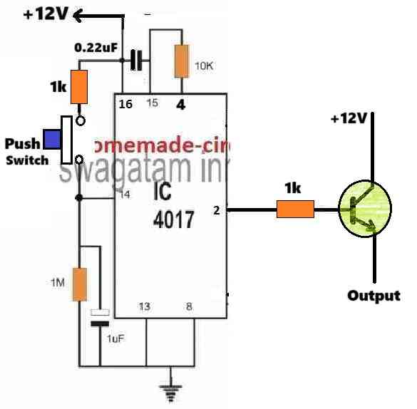
Ok, you are actually referring to a separate flip-flop circuit for implementing that function.
In that case you can try the “2) Accurate CMOS Flip Flop Circuit Using IC 4093” from the following article:
https://www.homemade-circuits.com/build-these-simple-flip-flop-circuits/
The input trigger can be applied through an instantaneous switch configured with the positive supply.
The relay can be eliminated, and instead, the emitter of T1 can be connected with the 4017 circuit positive supply line and the collector with the Source positive supply.
Awesome. Yep that is exactly what I need and will be able to reuse it across a number of projects. In terms of merging this flip flop circuit with the stepper controller, are you saying that the T1 CE channel just replaces the switch at the top right of the stepper controller schematic? Also I see the supply for the Flip Flop is 5-15V, so I could just use a 12V circuit and connect the lamp in your schematic directly to the “top” rail.
Yes, that’s correect! T1 CE channel just replaces the switch at the top “LEFT” of the previously shown stepper controller schematic.
You can use +12V at the collector of this transistor, but then you may have to add a 7805 IC at the emitter of this transistor so that a regulated +5V can reach the 4017 circuit and the motor.
The top rail is the +5V supply for the 4017 IC and the stepper motor. The +12V is separately given to the 12V lamp…
Great thanks. I will work on this and get back to you with the next steps if I cant work it out. Can I not run the 4017 and stepper circuit off 12V? Btw, which software do you recommend for simulating and creating schematic circuits.
Sure, no problem! If you use a 12V stepper motor, then everything can be run with a single 12V supply.
I don’t use any softwares, i use my brain simulation to judge the circuit working, so can’t recommend any softwares.
Nice 🙂 thanks for your feedback…let me know if you have any further questions regarding this topic?
Chào ngài, tôi đã gửi sơ đồ cho ngài.
Thank you so much Thieu, I have posted the diagrams at the bottom of the following post, I hope it will be of immense help to the readers who want to build a perfectly working high power stepper motor driver circuit.
Many thanks again!
Hi sir, how do I provide the circuit diagram.
Can you please guide me to post it.
Thank you Thiệu,
Please send it to my following email ID, I will check it out:
homemadecircuits
@gmail.com
Dear sir, to make the stepper motor operate with all coils (full bridge), you must use 8 transistors: 4 N channels and 4 P channels or 8 mosfets (4 N channels and 4 P channels) installed in an H bridge. The circuit
works well and the stepper motor runs well, consumes small current, high torque.
Thank you so much Thiệu, for the interesting information,
It would be great if you could provide us with the circuit diagram, the readers would love to see it.
Chào ngài, tôi ráp mạch cho moto bước đúng, cấp điện Dc 5v song moto không quay.
Tôi xin hỏi ngài Ic 4017 sao không thấy cấp điện DC vào chân 16 để nó hoạt động.
( moto bước của tôi nhà sản suất ghi 4,7 v.)
Hello sir, the 555 oscillation part of the IC must be adjusted like creating an inverter oscillation. (keep the capacitor C 1u).
Supply power to the 4017.
Test with an LED light to see if the LEDs light up sequentially at the 4017 pins.
To make the stepper motor run, you must permute (short-circuit the 2-4 motor wires) and it ran.
Thank you so much Thieu, for the valuable information, I appreciate it very much!
Hello Thieu,
You are right, pin#16 of 4017 must be supplied with a +DC supply otherwise the IC simply won’t function. It is mistakenly not shown in the diagram.
Please do this and let me know the results.
re the four wire stepper motor. Only four wire indicate its a bipolar stepper motor and it will need an H-bridge (actually, two H-bridges or a halve bridge on each wire. There are two coils, each with a wire on each end, that you can identify with an ohms meter. On on coil, pull one side to +v and the other to ground, disconnect and do the same to the other coil. You can control the direction by which wire is +v and which is ground. The voltage may be on the motor or it may be some multiple of 3 volts if small. I have seen 12V, 24V and 36V on medium size motors. If there is a part number your search engine of choice may find a data sheet. Note that the counting IC is CMOS.: handle as little as possible, only handle when grounded through resistor, maybe 100K Ohm, and ground unused input pins (all are). If using TTL or another chip (i.e. Arduino) put a 1K resistor between the chip an the transistor base.
Thank you for your feedback and the valuable information!
Thanks for the pattern
it is very ductile and can be easily adapted even to larger motors with different currents and voltages just add 4 Tr of power
Mario I2MBE
mbeelettronica@libero.it
Thank you for updating the info!
Hi there,I’m needing some help. I have a stepper motor from an old scanner that its 1.8 Deg/step 4.1 ohms and has 4 wires. I’ve tried different ways of connecting it and can’t seem to get it to work right. Can you or anyone help me on this? Thanks
Hi, I think you can customize the above explained concept to suit your motor specs. You will need to teak the IC 555 output frequency and PWM for this…
Simple motor drive circuit using ic555 & ic4017 in this project the ic 555 circuit is work like astable or monostable or bistable
It is configured as an astable.
Hi sir, greetings to you, pls sir does this circuit work perfectly?
Solomon, this circuit was submitted by another author, so I can’t guarantee the results!
Can Mr. Ankit help me?
it was a long time back he posted this article, not sure where we can find him. You can try finding him facebook hopefully.
Have you used 9V dc source in your unipolar stepper motor project? I have done full circuit diagram in proteus 8 proffessional which is given in your procedure. But can’t find final output after switching run mode. Please help.
Sorry Tanvir, I am unable to help you with this project because it was designed and contributed by another author Mr. Ankit. It was simulated and tested by the author himself and not by me.
However, in the simulation video it appears that a 9V batt has been used, so you can try with a 9V supply input
Ok brother.
Can you provide the same experiment using bipolar stepper motor?
sorry, I have not yet researched about this topic fully, I will surely update once I learn the details.