In this post I have explained the datasheet, specifications, pinout configurations and a few application circuit for the IC IRS2153 which is a half-bridge IC from Texas Instruments. The unique feature of this half bridge driver is that it does not have to depend on external logic sources for the operations, rather allows configuring its own oscillator through a simple RC network.
The IC IRS2153(1)D which is fundamentally a half-bridge mosfet driver chip can be actually used for a number of different interesting circuit applications such as boost converters, solar compact inverters, and if two of them are coupled can be even configured as a full bridge mosfet driver circuit. I have explained more about this interesting device.
Main Electrical Specifications
Before I have explained the potential applications of this chip, I have explained a few of its main features first:
- The chip is designed to withstand and operate with voltages as high as 600V DC (15.4 V Zener clamp on VCC).
- Consists of an internal built-in oscillator circuit with a 50% fixed duty cycle, while its frequency can be simply determined through two external R/C components (CT, RT programmable oscillator).
- Consists of a built-in high side driver network which allows a fail-proof conduction of the high-side mosfet (upper mosfet) with the required essential boot-strapped gate voltage.
- Allows an external shut-down feature to be enforced just by adding an additional transistor stage with the IC (Non-latched shutdown on CT pin (1/6th VCC). This feature can be very useful for applications where an automatic current or voltage regulation is crucial.
- The chip also includes a Micropower start-up feature which assures guaranteed initialization even under relatively minimal voltage and current conditions.
- An internal dead time feature ensures perfect separation between the outputs for fail proof operations.
- All the the pinouts are ESD protected internally for safeguarding the chip against static voltages during packaging and handling.
Basic Circuit Configuration of the IC
Understanding Pinouts of the Half-Bridge Driver IC IRS2153(1)D
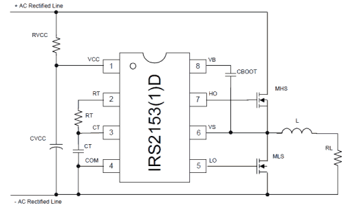
The figure above shows the standard circuit configuration of the proposed half bridge IC. The pinout functions may be understood as follows:
Pin#1 is the Vcc of the IC and is internally clamped to 15.4V for safeguarding the IC from high supply voltages.
The RC network made from RVCC and CVCC has two important functions, the resistor hleps to control the current to the internal zener while the capacitor provides a start up delay to the chip so that the outputs are able to initiate with zero logic until the built-in oscillator has begun oscillating.
The resistor Rt and Ct across pin#2,3,4 is the external RC network which determine the oscillator frequency (duty cycle being fixed to 50% internally).
The following formula can be used for determining the oscillator frequency:
f = 1/1.453× Rt x Ct
Pin#4 is the ground terminal of the IC.
Pin#7 and pin#5 are the High and Low side outputs of the IC, meaning pin#7 drives the mosfet which is connected with the supply voltage while pin#5 is responsible for driving the mosfet connected with the ground rail.
Pin#8 is terminated with a Cboot capacitor which ensures that the HO and LO never conduct together and also steps-up the required bootstrapped voltage for the HO pinout of the IC.
Application Note:
The main application of this IC hovers around inverters and converter topologies.
One standard inverter application design can be seen in the below given diagram:
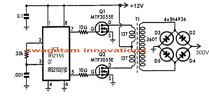
The simple inverter design shown above using the IC IRS2153 can be used for driving mains CFL lamps from 12V supplies.
Here the Cboot feature is eliminated because the configuration is an ordinary center tap type inverter which does not call for boot-strapped supply due to the absence of high side mosfet network here.
The transformer may be wound over any standard 27mm E-core type ferrite assembly, as shown below.
For the complete datasheet you may refer to the following post:
irf.com/product-info/datasheets/data/irs2153d.pdf
Questions & Answers
sir pleese filament bulb /led light for ferrite transfomer rewinding + 200w inveter circuit denna
Sanil, sorry I don’t have this circuit with me at this moment…
Great information that I find here… but I have a super doubt, it is about the S21531D, such as “15.4 V zener clamp on Vcc”. If the voltage on the pin is higher, do I burn it?
Thank you, and Glad you found the post useful. Yes the IC has an internal 15V zener clamp at pin#1 Vcc. You can use RVcc upto 100K so that the resistor does not burn at high voltages.
I want to know if irs21531d is equal to ir21531d and I also want to know if an ic with the same numbers and different sizes or sizes for example an smd is equal to an smps with the same number thanking you very much
I checked their datasheets…. both the ICs looks identical to me with identical working specifications.
I am not totally sure how these IC’s work. If I increase the frequency is the pin output currents at 5 and 7 reduced?
Current is not relevant since mosfets gates are used across the outputs. If you increase the frequency of the IC then the output frequency will also change accordingly
Hello, I made this circuit and am having problems with the mosfets heating up. I am using irlb8721 and a frequency of around 20khz. I am wondering if maybe my transformer is acting as a short circuit as 20 khz is on the low end for ferrite core any thoughts on this? Also with a dedicated half bridge driver are the 10 ohm resistors necessary between the IC and mosfet gates?
Hello,
I guess you are referring to the second circuit. It was taken from one of the reputed pdf articles online, and it seems the circuit is a tested design.
Yes frequency does matter, and is directly related to the number of primary turns of the transformer. In that case you can try increasing the frequency by reducing the Rt, Ct values.
Yes a low value gate resistor is recommended for mosfets even if it is driven from a dedicated driver.
I have 3 turns on the primary and 95 turns on the secondary. It is thick wire which fills a ee42 transformer completely. Do you think this would be ok?
The number of turns should be exactly as shown in the second diagram, if you are trying to build that circuit. The number of turns cannot be judged, it will need to be either calculated or adjusted through some trial and error.
Ok, with the original transformer what was the maximum watts?
Thanks,
Jon
The watt will depend on the wire thickness, and the overall size of the transformer, it will need to be experimented.
is Isolated gate drive half bridge inverter possible with this IC? Please give me schematic for inverter.
No it is not possible, due to the bootstrapping.
Hello Swag,
Is IRS2153 the same as IR2153?
Hello Olusegun, as per their datasheets they both look almost same with their specifications
Please ask this question under induction heater article, I will try to answer!
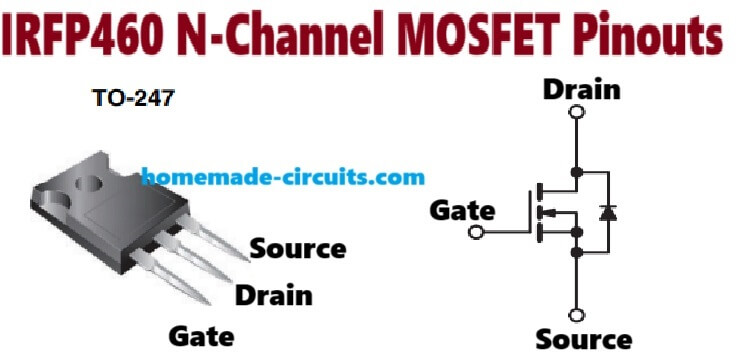
Sir how many pairs of mosfet (Ex. IRFP460) can anIR2153 drive?
Any number of MOSFETs can be added in parallel
Thank you very much Sir for this wonderful explanation, the best I have found on the web.
I am trying to understand how an H bridge works. My aim is to build a small sstc. I have tried the ZVS Mazzilli, but almost all the time I end up burning my MOSFETs.
I would like to simulate this circuit in LT Spice but the IRS2153 is not among the models. Do you know a place where I could get it?
Thank you very much, and thank you again for your detailed explanations. It helps people like me who are just beginners.
Thank You Klaus, I appreciate your thoughts, and glad you liked the post!
I can’t suggest much regarding simulation softwares, since I myself do not rely on these devices…instead prefer testing circuits practically, and sort out the issues practically.
IRS2153 type of designs are proven by the datasheet engineers so no doubt they will work correctly if everything is put up correctly in the assembly.
saludos amigo podria utilizar ese circuito para hacer una hornilla de induccion con 110 volt retificados y igbt como seria el circuito
Yes, the above IC can be used as a induction heater application. One example design can be seen in the following article:
https://www.homemade-circuits.com/solar-induction-heater-circuit/
How do you stop the chip in case of overcurrent?
By adding the following technique to pin3 of the IC
How to Make Adjustable Current Limiter Circuits
Dear Sir,
I want to use IRS2153D in Electronic Ballast Application (For, T8/36W Fluorescent Tube). Can you furnish me circuit diagram of the same. Supply Voltage :230Vac.
Is there any formula to use various other wattages of the Electronic Ballasts (i.e:T8:58W,80W etc).
Your Prompt response in this regard will be highly appreciated.
Hello Mukesh, there are a few related examples in the following article which you can refer for detailed info.
https://www.homemade-circuits.com/make-efficient-electronic-40-watt-tube/
hi dear sir i wanted to know if the high side mosfet turn on through pin out 7 and pin out 6 or not it turn on through pin out 7 and L and R my mean the first photo
pardon me for bothering you
Hi sedigh, yes the high side mosfet turn ON/off via pin7/6. RL refers to the connected load
Dont we need a resistor to go between the gate and source?
Thanks in advance.
You can add it for improved safety!
Thanks Swagatam.
Can you point a link to the video / article of yours on a DIY transformer?
Hi Madhav, presently I don’t have a video for DIY transformer.
Last comments here were long time ago. I hope I will answered quickly.
Please I need to understand this ic ir2153 properly. I want to use it for a switched mode power supply and I don’t know how to go about the high side and low side mosfets. What type of mosfets can be used here? Between an enhancement mosfet and a depletion mosfet which is the most suitable?
And why do we need to connect the source of the high side mosfet to the drain of the low side mosfet as shown in the normal ic ir2153 circuit.
What type of circuit are you looking for, half bridge or full bridge?
You will need enhancement type mosfet, and Cboot capacitor can be a 1uF if the frequency is high.
I want to build a power supply with a half bridge mosfet connection.
Isn’t there any formula for calculating cboot.
And also, what is the power supply voltage range for the ir2153.
Are there different versions of the ir2153 like ir2153d and ir2153(s)?
Please can you also explain why we need to connect the source of the high side mosfet and the drain of the low side mosfet together. Can’t you separate them in your connection?
..sorry forgot to give the formula, here it is:
Thanks Swagatam, but isn’t there any way I can post a pic on this page.
I wanted to drop a pic of a particular circuit of the ir2153 which don’t understand very well.
Please, I need your help Mr Swagatam.
Victory, you can upload the pic on any free image hosting site online and send the link to me here, however there’s only a standard way of configuring the IC which is explained in the above article.
There’s a formula, you can see it here:
The MOSFETs are connected in the shown manner to enable push pull operation on the load. Load will not work if the MOSFETs are separated. Normally the other end of the load is connected with the ground of the supply, while the MOSFET supply pins are connected with +/- of the source.
I am not sure about the other variants, you can check the datasheets for the info
Bro
Can we use pin 8 of ir2153 ic in the same way we use pin 4 of the 555 ic (reset pin)? See, I want it to produce a square wave but not continuous, instead bursts of square waves with another ic telling it to stop, say, every half second.
Hi Mooney, Pin#8 is not th reset pin of IR2153, it’s the High side floating supply voltage pin.
You can use pin#3 instead, each time you ground this pin the IC output will become void instantly, halting the switching process.
Dear sir,
I had like to use two Irs2153DPBF to drive a full bridge (not tried yet)
How to connect the two IC in order to prevent the second one to oscillate by itself but instead at the same frequency as the first one (but with a 180° phase shift) ?
I forecast to use CT pin on the second one as a Trig pin by connecting it through a R divider and R to the LO pin of the first one (and if phasing is not good, to use a General Purpose BJT to invert the signal).
But if you have done it already or know of a solution …
Thanks
JJL
JJ, this IC may be difficult to optimize for your requirement, instead you can use the one explained in the following article
https://www.homemade-circuits.com/three-phase-inverter-circuit/
I have an interest in this chip. However, the fact that it has no provision for feedback limits its application. Am I wrong? Maybe in just don’t know how to implement the feedback. Please could you share? Thanks
Please I’m not clear yet. Can you be a little more elaborate. What do you mean by ‘self-regulating facility’? In my opinion, Automatic shutdown is not a true feedback mechanism, as it does not keep the output constant with a change in battery voltage, it only shuts it down completely when the voltage goes beyond a threshold. Is there no means of achieving a real feedback that keeps the output voltage constant?
Thanks.
it can be used for the mentioned purpose, because as soon as the the IC would be experiencing the shut down, the output voltage would be experiencing a drop, and this would instantly disable the feedback from the shutdown, allowing the IC to function again…this process would happen extremely rapidly maintaining a constant voltage or current at the output.
all feedbacks work in this principle, sometimes narrowing of PWM is used instead of shutdown, which is again quite similar because when PWM is narrowed the output voltage drops…
pin#3 of the IC is the shut down pinout, if you configure the feedback with this pin then you can enable the IC with an aitomatic shut down or a self-regulating facility.