In this post I have explained how to convert 3 phase AC to single phase AC through a special bridge rectifier at any desired voltage. The idea was requested by Mr. Chaquito
Technical Specifications
You have a very nice page and I find it really good, If been looking for a 380V 3ph converter to 230V, it should with held at least 3-5 KVA. Not sure if you have one or
would you be able to direct me to one.
I have a 3ph input of 5.5KVA from a generator that I would like to convert to one single output of 230V +- 3-5 KVA. Doing the usual ph to neutral per ph would not give me a strong KW output. Transformers are very expensive.
I would appreciate your help thank you.
Chaquito
The Design
The question how to convert 3 phase AC to single phase AC can be solved by first rectifying the 3 phase AC to DC and then converting the DC back to 220 V AC through a full bridge driver IC and H-bridge mosfet network.
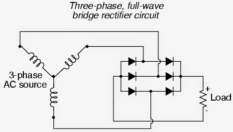
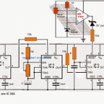
The first stage intended for converting the 3 phase AC to DC may be executed simply by the traditional diode bridge network, as may be witnessed in the following diagram. After filtration this would produce a peak of 530 V (with a filter capacitor of around 10uF/1kv included across the load)
Now, once the 3 phase rectified DC is achieved, this will need to be converted to the desired single phase AC, as per the request this value should be 220 V.
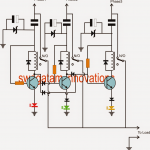
A full bridge mosfet driver topology may be incorporated for implementing the above requirement, as shown in the following diagram:
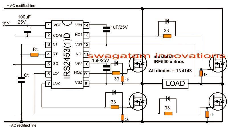
The layout looks simple and easy to configure, however it would produce and subject the load to the full 530 V instead of the specified 220 V.
The issue can be normalized and controlled to the desired levels through an external voltage sensor circuit, which could be further integrated with the Ct pin of the IC IRS2453.
The simple solution can be implemented by incorporating the following circuit:
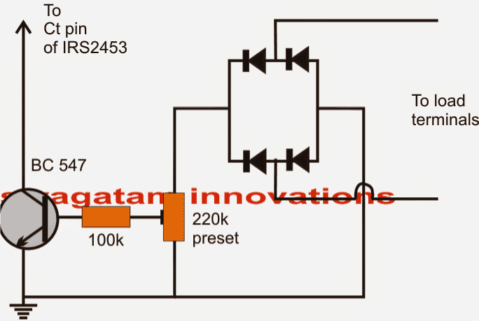
The 220k preset is adjusted precisely so that the transistor just begins conducting at voltages around 240 V across the load.
When the transistor conducts, the Ct pin is grounded at that instant, forcing the IC to inhibit its oscillations which in turn renders the high side outputs to go low, cutting off the rectified high voltage to the mosfets.
This results in lowering down of the voltage across the load which allows the BC547 to switch OFF and restore the IC operations....the procedure repeats making sure that the output stays under control and at the specified 220 V level.

Questions & Answers
Hello Mr. Swagatam,
Can you tell me how the factor (3√3 / π) coming from when 3 phase AC to DC rectified?
Why we use this formula?
Hi Bibhas,
It is for converting the 3-phase AC RMS (line voltage) to the average DC output at the output of a diode bridge.
Suppose your 3 phase RMS is 400V, then:
Vdc = (3√3 / π) × 400 ≈ 1.6547 × 400 = 661.88V DC
That’s the average rectified DC voltage at the output of the bridge rectifier…
I need 12 Kva three phase to single phase transformer.How much will it cost.
How can you make it to produce atv50hz? Thanks
By adjusting the Rt, Ct values of the IC appropriately.
Hello ,how are you ?
I do have a similar question concerning 3 phase to single phase .I have a 24 volt DC motor chained to a electric scooter back tire (spinning it),and I have 3 ,3 phase hub motors ,touching and being spun by the tire.(hoverboard ,hub motors).each motor has 3 phase ac at 36 to 42 volts.before be fore it’s rectified to DC I ran 2 legs of 1 3 phase output thru a stepup transformer and I have 135v ac.my question is ,how do I step up all 3 legs of each motor and change it to single phase.this should give me 3 separate 120 volt single phase supplies,please help and thank you
Hi, for 3 separate outputs you will have to replicate 3 of the above circuits and then use them separately as explained in the above article.
Good day Swag, please a 3phase motor connected to single phase, on idle it draws 1.72Amps with 220v but on load, it draws 1.25Amps, what could be cause.
Hi Tinu, how did you connect a 3 phase motor to a single phase AC outlet? I am not actually sure how it draws less current when loaded….
Hi Swagatam,
Thank you for your useful post on the topic of 3 phase to single phase conversion. I have a similar issue that I seek your assistance with.
I have a 3 phase 415 V 50 Hz AC power supply from a solar inverter. I want to power a 1 HP (0.75 kW) single-phase water pump with my inverter. However, I cannot simply take a single-phase from my 3 phase power supply to start my water pump, as it causes a phase imbalance and the inverter trips.
How can I convert my 3 phase 415 50 Hz AC power supply into a single-phase 240 V 50 Hz AC supply, making use of all 3 phases?
As I understand it, I could use the original example of the full bridge driver IC and H-bridge MOSFET network. Is that correct?
What is the efficiency of the conversion/are there any major energy losses in the proposed type of conversion? Is there a way to achieve the same conversion with a transformer that would be more efficient (perhaps it will also be more expensive)?
Thanks so much for your help.
Best,
Maligaon
Thank you Maligaon,
Yes, the method suggested above is perhaps the only technically correct way to accomplish a 3 phase to single phase conversion. The efficiency can be quite high around 90% according to my knowledge.
Hi, This is very interesting. Something like this is also used when charging electric cars here i Denmark. A lot of cars coming here from asia and france carges via 1 phase 230v and 32A. But here in Denmark it is not allowed to draw more that 16A on a single phase. so it is a very slow way of charging at only 3,6kW. But a couple of wallcharger suppliers can mount a transformer before the charger, to take 2 of the phases and give 1 phase 24A. That gives you 6,6kW which make a world of a difference in chargetime. That is just a very expensive transformer solution and can only be used when charging at home, not on the public chargers, because it is mountet before the charger.
Would it be possible to build a lightweight electronic 2 phase to 1 phase converter, and mount it on the type 2 charge cable after the charger, so it sits between the charger and the car? This would make it portable and usable anywhere.
Thanks in advance.
Torben
Hi, thanks, and glad you found the post helpful!
Yes it possible to convert 2 phase to single phase, by rectifying the 2 phase output into a DC and then using the DC to operate a full bridge inverter.
Sayın SWAGATAM.
Einhell marka bt-900 model 1 kw sessiz jeneratörun inverteri bozuldu.jeneratörden üç faz çıkıyor.bana üç fazı tek faza dönüştüren 1’lık inwerter şeması gönderi misiniz veya yayınlar mısınız?
Dear Swagatam.
Ben bu devreyi inverteri olmayan 1000w silent generatorda kullanacğım.jeneratordan 3*190voltu doğruttum voltaj 220 volta nasıl ayarlanacak?
Hi Sezgin, you can use the second schematic using transistor for controlling the output to 220V. For higher accuracy you can use an op amp circuit, as explained in the following post:
Automatic Inverter Output Voltage Correction Circuit
Dear Swagatam, thank you for your interest.
If I apply the second scheme to the ct pin, I will have given a voltage between 0 -330v to the ct pin input;
1- Does the Ct pin carry such a high voltage?
2- Does the ic2453 -Rt balance not deteriorate. Doesn’t it stop working?
If you post the full schematic then the worries are gone.
Thank you very much.
I understand your concern, however the inverter high voltage is dropped by the 220K preset and the 100K resistor at the transistor base. Although the circuit may not be isolated from the inverter voltage and might cause a shock if touched manually, it will not harm the IC.
Still if you are concerned about the issue, you can use an opto coupler based feedback. If possible I will try to update the design soon.
Rt and Ct what is for 220v 50Hz?
You can find the formula under this article:
https://www.homemade-circuits.com/half-bridge-mosfet-driver-ic-irs21531d/
I have a 6 KW, 440 V, 3 phase (with neutral) off grid solar inverter feeding the whole house. It can withstand max 2.2 KW per phase. The power limitation prevents me from using dish washer/washing machine on inverter. I am looking for a cheaper solution.
Can you give me a working design for a converter which will take 3 phase input from solar inverter, rectify to DC and reconvert into 6 KW, 220 V, single phase supply to power these appliances. The load of house does not increase above 5 KW
The present solar inverter is essential to power the 2 KW, 440V, 3 phase motor for the lift, which is intermittent for 25 seconds at a time.
The solution is the same as explained in the above article, but building the inverter can be a difficult job for any newcomer, so you can buy a 300 V to 220V inverter readymade, and use the 310V DC from the bridge rectifier output to operate the inverter
Can I do it at low power
yes that is possible…
Hi I’d like to convert a 15kw 3 phase Onan generator (15JC-4r) to single phase. Would you know how to do that?
Thanks
Hi, it is explained in the above article, although it will produce a square wave output
Would you help me figure out exactly what I need and how to put it together if I sent you the specs on the generator? I need it to run a 50 amp 208/220 geothermal heat pump, and the rest of my house, or at the least just the heat pump.
I will try to figure out if it is feasible for me, you can send me the specs.
I had an idea. Do you think I could hook the neutral, and two legs of the generator to the panel for 110/220 then use a transformer on the third leg to boost it to 220 and hook that to the panel, or will it short out?
I will need a schematic drawing to simulate its proper working
That would be great! Thanks Swagatam!
The Generator is an Onan 15JC (15kw) three phase, and I need to convert it to single phase. I can get single phase 220 from two legs, but that will only give me 10kw. I believe I need at least 10,400kw or 11,000kw (50 x 208 or 50 x 220) to run my heat pump. Thanks!
Do you know where I could get one? Are they expensive?
You can search online, yes they will be expensive depending on their size!
According to me the idea explained above is the only legit and efficient way of transforming the full 3 phase power into the single phase output, or alternatively you can use a 3 phase to single transformer to do the same.
Hello Swagatam,
I hope my question is not too off-topic!
I live off grid, with power provided by solar panels. I then have Victon Quattro controllers to charge my lithium batteries, and supply my house with 230V AC.
Since the sun does not always shine, I recently bought a vertical axis wind turbine. The output of the turbine is 3 phase AC, with voltage anywhere between 0V and 90V depending on the speed of rotation. The maximum power is 4kW. It came with a charge controller, which simply converts this into DC before heading off to the batteries.
The problem, to my very amateur mind at least, is that this charge will only get into the batteries if the controller output voltage is higher than the battery voltage, but not above the maximum voltage the batteries can handle, so it needs to be between 52V and 57V.
If this is correct, is it possible to convert the 3 phase, AC turbine output to a usable DC voltage? I’m assuming the charge controller that came with the turbine is not really fit for purpose.
I hope you can help.
Many thanks,
Matt
Hello Matt, You can employ the first circuit idea posted in the above article for converting the 3 phase wind turbine output into a DC for the battery charging. However, you may have to use a charger controller between the output of the shown diode bridge and the battery for safeguarding the battery from overcharging.
Dear Swagatam,
Does the VCC voltage on the IC IRS2453 have to be exactly 15V? Would 10-12V work?
Hi Collins, 12V will also work.
Dear Swagatam,
Won’t the voltage sensing circuit interrupt output power supply making it unstable? What stabilizes the circuit then?
No it won’t.
Good day sir
Your page its been helpfully through out my researches.
May you please help with a Design project which is as follows,
Single phase to three phase power supply.
The power converter must be able to convert the single phase 220~240 VAC supply to balanced three phase 220~240 VAC to power a three phase AC motor.
It would be much appreciated if there is any book that you can refer me to or any information that you can share.
Thank you.
Nyiko
Thanks Nyiko,
you will need a 3 phase driver IC for the required application.
You can refer to the following article:
https://www.homemade-circuits.com/arduino-3-phase-inverter-circuit-with-code/
see the 4rth diagram from top, you can use this concept to convert single phase to 3 phase.
For the supply to the MOSFET drains, you will have the rectify the single phase supply to DC 310V and feed it to the MOSETs drain…the output will be then a 3 phase 220V
Dear Sir, I read your all post, your every post is very practical and easy to understand. I build some circuit form your guidance and detail explanation. sir, sorry to disturb you, but I need this circuit very urgently.
Myself work in a Industrial sewing machine company, we give 440 volt motor along with sewing machine but production unite run with 220 volt AC. My humble request is to you, can you please sell us this kit or give simple circuit, so we can make this circuit.
sorry for inconvenience.
Dear Avishek, Are you looking for a 3 phase to single phase converter circuit? In that case you can try the one explained above. But is will be a square wave circuit.
Do u have 3 phase to single phase converter with Vfd circuit kit then please let me know & also kits prise list.
sorry presently I do not have a ready made kit for this…