In this post I have explained how to make a simple IC 555 based alternate relay timer circuit for toggling a couple of loads alternately with a specified length of delay, as determined by the calculated values of the relevant components. The idea was requested by Mr. Sanjoy.
Circuit Objectives and Requirements
- I am a regular reader of your excellent posts. Here I would like to request a circuit design.
- I am trying to build a laboratory paper coating set up for which I am going to employ 2000 watts hair driers for drying of the coated paper.
- The problem is that those driers can't be run continuously.
- Therefore I decided to use two driers alternately for three minutes each. But alternate switching of these driers manually always is tiresome.
- So I request a circuit which will be able to switch on and switch off the the driers alternately and automatically for a preset period of time and continue doing this until switched off.
The Design
Referring to the below shown alternate switching relay circuit, or we can also call it an alternate switching flasher circuit, the idea may be understood with the help of the attached explanation.
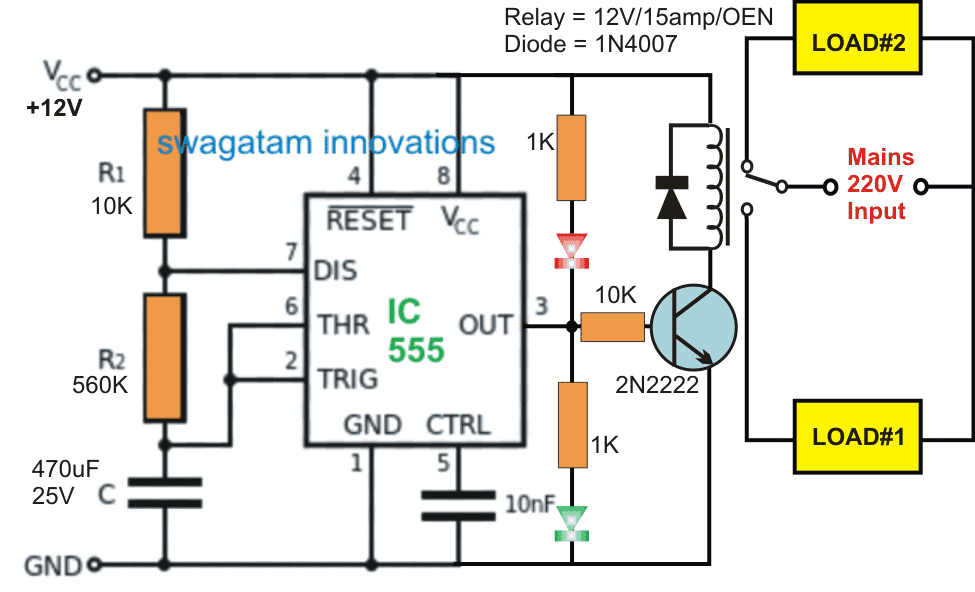
The circuit is built around a standard IC 555 astable configuration, which basically produces an alternating high and low or an alternating 12V and zero volt at its pin#3 when switched ON.
This alternately switching output accompanies certain delay between its ON/OFF switching as determined by the component values of R1, R2, and C.
In the proposed design the values of these timing components are suitably calculated to produce an approximately 50% duty cycle, and having a delay length of around 180 seconds or 3 minutes.
With the shown arrangement, only the value of the 470uF capacitor needs to be altered for achieving other preferred time delays across the output pin#3.
The pin#3 can be seen connected with a transistor relay driver stage which responds to the high/low pulses from the pinout and accordingly switches the relay contacts across the N/C and N/O contacts.
Since the two loads are connected across these two contacts of the relay, these are also alternately switched from ON to OFF and vice versa with a delay of 3 minutes between each switching.
The two LEDs connected across the supply pins and the pin#3 of the IC helps to indicate which load may be in the switched ON or OFF position at a given instant.
The above explained alternate switching relay timer circuit can be also implemented for other identical applications and the ON/OFF periods can be independently adjusted for achieving different ON/OFF sequences, by suitably altering the R1/R2 timing components of the astable.
Calculations for R1, R2, and C1 in the 555 Timer Astable Circuit:
Let's say you want the both the loads to switch ON and OFF alternately with a time difference of exactly 50 minutes, then you can calculate it as given below:
The goal is to design the circuit to operate at a 50% duty cycle with an ON time of 50 minutes and an OFF time of 50 minutes.
Formulas:
Frequency (f):
f = 1 / T
Period (T):
T = (R1 + 2R2) × C1 × 1.44
Duty Cycle (D):
D = (R1 + R2) / (R1 + 2R2) × 100%
Data in Hand:
ON Time (T_ON) = 50 minutes = 50 × 60 = 3000 seconds
OFF Time (T_OFF) = 50 minutes = 50 × 60 = 3000 seconds
Total Period (T) = T_ON + T_OFF = 6000 seconds
Duty Cycle (D) = 50%
Step-by-Step Calculations:
Step 1: Calculate Frequency:
f = 1 / T = 1 / 6000 = 0.0001667 Hz
Step 2: Select C1:
You will choose a practical value for C1. For long timing a high capacitance is suitable.
Assume:
C1 = 100 µF = 0.0001 F
Step 3: Calculate R1 + 2R2:
Rearranging the formula:
R1 + 2R2 = T / (1.44 × C1)
Substituting the values:
R1 + 2R2 = 6000 / (1.44 × 0.0001)
R1 + 2R2 = 6000 / 0.000144
R1 + 2R2 = 41,666,667 Ω ≈ 41.67 MΩ
Step 4: Split R1 and R2 for 50% Duty Cycle:
For D = 50%, R1 = R2.
R1 + 2R2 = 41.67 MΩ
R1 + 2R1 = 41.67 MΩ
3R1 = 41.67 MΩ
R1 = 41.67 / 3 ≈ 13.89 MΩ
R2 = R1 = 13.89 MΩ
Verification of ON and OFF Times:
ON Time (T_ON):
T_ON = 0.693 × (R1 + R2) × C1
T_ON = 0.693 × (13.89 + 13.89) × 0.0001
T_ON = 0.693 × 27.78 × 0.0001
T_ON = 0.001923 seconds ≈ 3000 seconds (Correct)
OFF Time (T_OFF):
T_OFF = 0.693 × R2 × C1
T_OFF = 0.693 × 13.89 × 0.0001
T_OFF = 0.000962 seconds ≈ 3000 seconds (Correct)
Final Component Values:
R1 = 13.89 MΩ
R2 = 13.89 MΩ
C1 = 100 µF
This configuration will give you an IC 555 astable circuit with a 50% duty cycle and an ON time of 50 minutes and an OFF time of 50 minutes for a total period of 100 minutes.


Questions & Answers
A very goodevening Bro!
My question is- can we modify above circuit for low power supply operations. I would be using this for alteranate switching using as low power as possible, probably 5 – 10v. But the circuit above uses 12v. But I presume that we can do it some way, may be by using a 5v spdt relay.
Please answer in simple terminology as I am new comer to this vast field of electronics.
Thank you and wish you a very happy new year!!
Hey bro, good morning, Happy New Year to you!!.
You can definitely use 5V for this circuit with a 5V relay. 555 ICs can work with 5V DC also. If possible you can use a CMOS version of the 555 IC such as 7555 or the LMC555, which can work even with 3V DC supplies:
https://www.homemade-circuits.com/cmos-ic-lmc555-datasheet-works-with-1-5-v-supply/
Sir,
is there any circuit that is on delay and off delay compained. that is when the power is on, the out put must be after a certain time and when the power is off, the out put must be still on for a certain delay period.
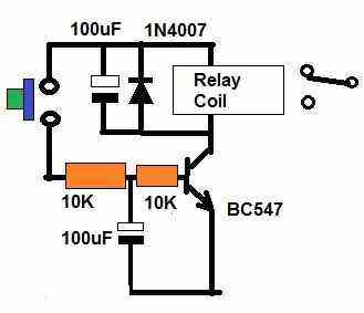
Hari, you can try the following design and optimize the BJT base part values to adjust the time delay as per your requirements:
Hi Swagatam. Am a strong follower of you and have been using few of your circuits to my requirement which are really great and I humbly thank you for sharing them here.
Now I need your help in another project for my son somewhat similar to the above. The requirements are as follows.
The project involves 4 motors and they are to be run with different time and gap.
when the switch is on,
Motor – 1 & 2 : Door opening – Sequence 1 (two doors and hence 2 motors)
Motor – 3 : Water flow — Flow for 1 minute – Sequence 2
Motor – 1 & 2 : Door Closing – Sequence 3
Motor – 4 : turn (360 degree) with an object placed on the motor – Sequence 4
Motor – 1 & 2 : Door Open – Sequence 5 (should stay open for 5 minutes)
Motor – 1 & 2 : Door Closing – Sequence 6
Motor – 4 : turn (360 degree) with an object placed on the motor – Sequence 7
A gap of 5 sec in between each sequence is needed. Motors 1 & 2 need to run in different direction.
Motor 4 has 2 objects placed back to back on the motor. Each turn will show different object.
Thanks in advance and looking for your help at the earliest.
Thank you Nagaraj, I greatly appreciate your kind words.
This will require an Arduino coding.
Let me figure it out, and I will try to design it soon for you.
Please be in touch…
Thanks for your prompt reply. Really appreciate your kindness for helping many people who are in need of a mentor like you.
Waiting for your reply at the earliest.
Thank you in advance.
No problem Nagaraj, can you please tell me how much time the door motors need to operate, or is there a limit switches for this?? Please let me know….
I have no idea on using limit switches here. If need kindly suggest me on this.
Hi
The motors 1,2 & 4 are small gear motors and operates with 3-5 volts only. The doors are very small (max of 5 inches in height). So the motor has to facilitate the door to open and close. I think it may take just 1 or 2 sec.
OK, then you can use the following data to control the motor sequence:
Arduino code:
https://www.homemade-circuits.com/wp-content/uploads/2025/11/Arduino-code.txt
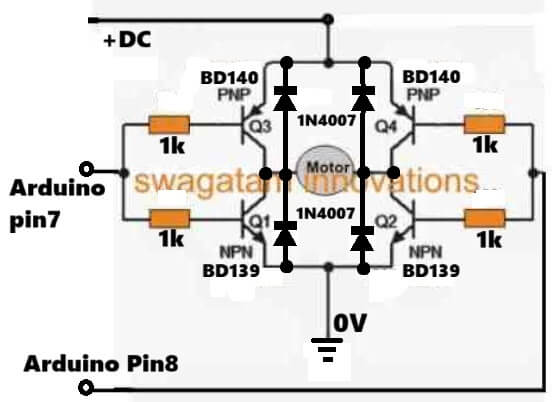
Motor driver circuit for Motor 1 and motor 2 (both in parallel)
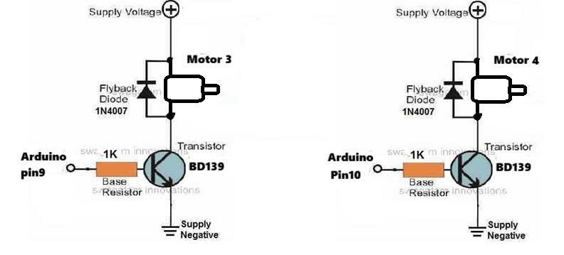
Motor connection for motor 3 and 4:
Hi,
I just made the circuit for the motors 1 & 2 as per your circuit given and tested without giving any load nor connected it to Arduino pins.
Here, I applied 5 volt (+DC) and when checked at the junction of both BD140 emitter pins, the voltage was 3v and 2.7v at the points after the resistors where it has to be connected to Arduino pins. Is this ok or any problem.
Am planning to go for SG90 micro servo motors. Hope this circuit will get along.
Hi, without connecting a load and Arduino input, you cannot verify the results.
Or alternatively you can connect the H-bridge inputs with a 4047 IC oscillator output, if you do not want to test it with Arduino initially.
Its ok. will complete the circuit with Arduino and check. Thanks for your timely response.
Also I had asked you whether I can go for SG90 micro servo motors in the above given circuit. Kindly suggest me accordingly.
Sure, no problem.
Servo motor cannot be used, you will have to use Permanent magnet motor, with gear box.
Am really thankful for your timely help. Will follow all your instructions.
Can you suggest a suitable Arduino board for this?.
No problems at all, please let me know if you have any issues with the circuit…
Arduino board can be an Arduino UNO ….
Morning Sir ji, I’ve built this project and it’s working flawless. Got a BJT timer on your site for including accurate 50m switching time!
https://www.homemade-circuits.com/how-to-make-long-duration-timer-circuit/
Now I’ve a requirement to complete!! I want to include this one without any push button so that the ckt can have an accurate 50 mins switching time between two loads! And if possible, you can help by just modifying 555 timer by just including any trick like diode-resistor trick adopted in BJT timer.
Thank you for everything Sirji!
Awaiting for your suggestions!!
Happy New Year!!
Thank you Maddy for updating the info, glad it is working for you.
Do you want to include a push button in the above “alternate load ON/OFF circuit?” Because I cannot see any excising push buttons in the design?
There’s no need to do any tricks in this circuit, since the IC 555 is already too good, and does not require any external improvements.
I have 4 large electric heaters used to heat a room in our church. They are each controlled with a low-voltage relay. Currently the relays are all wired in parallel. I’d like to be able to have 2 on for 3 minutes, then switch them off and switch the other two on for 3 minutes. The idea is to reduce the electric demand charge by only having 2 on at a time. This circuit looks perfect. I am thinking to hook it up to a RIB (relay in a box) using the NO and NC option. Sadly I am a real beginner at this sort of thing. Any suggestion on where to get all of the pieces in your diagram?
You can easily get the parts from any online electronic spare part dealer…or you can even get them through amazon or ebay.
I want to make a circuit with dual supplies automatic changes over AC and DC when the main power failure then the DC supply on and when the main power on then the DC supply automatic off do you help me with circuit thanks so much
I have a few changeover circuits published in this blog, you can check them out here:
https://www.homemade-circuits.com/?s=changeover
Thanks so much for help
I have built a microcurrent therapy unit, powered by a 9-volt battery. Iam stuck on the last task, however. Can you refer me to a circuit (maybe centered around anoth 555 timer, CMOS) that would switch the unit on for five minutes then switcing it off for five minutes before switching it back on another five minutes, repeating etc.?
You can try the following 4060 based design:
Make sure to remove the 1N4148 diode link, it is not required. You can adjust P1 and C1 for adjusting the output switching delay.
What should i change for more timing delay ( 15minutes on and 5minutes off in loop)
You will have to experiment by using different resistor values for R1 and R2
I need a timer which will help me in circulating water on and off for a desired time.
Need your clarifications for the following points.
1. Can I use just one motor (Load) to be operated instead of two in the circuit.
2. If I need to adjust the on and off timing, will it be possible to go for preset replacing fixed resistor.
3. What relay should I opt for if I use a 12 v motor, or 230 V motor.
Here are the answers:
1) Yes you can connect a single motor either to the N/C or the N/O contacts depending on whether you want the motor to be switched ON when power to the circuit is switched ON, or start with the motor OFF when power is switched ON.
2) Yes that’s possible. You cab replace the R1 with a 1M pot or preset, but make sure to connect a 10K fixed resistor in series with this preset or pot.
3) Relay will depend on the motor current specs, if it is less than 5 amps then you can use the ordinary cube shaped relay having a coil resistance of around 300 to 400 ohms.
A very informative and useable project. What if more than two devices are to be included in the project? Can this be modified to include variable number of devices working for variable time and at variable intervals?
Thank you, only two loads can be used in this circuit, for variable time and variable number of loads, you will need to have many IC 555 arranged in a sequential form with variable time adjust
Hello
This is just what i need, i have build it and it works ok with a lite load, like a LED on load A+B, but when i put a pump on (about 0.7 amp), the timing goes fubar, and unequal and drops from 3min to about 1min.
Do you have a idea as to what goes wrong? hope i make sense. Thanks alot for your time.
Bo Andersen
Hi, Glad you could build it successfully.
The problem could be due to the strong motor transients the IC 555 timing might be getting disturbed.
Please do the following modifications to your IC 555 supply line.
Power the IC 555 positive line through a 50 ohm or 100 ohm series resistor.
Add a 1N4148 diode directly across the pin#8/4 and pin#1 of the IC. Cathode will go the pin#8/4.
Also add a 100uF capacitor parallel with the above diode. Positive of the capacitor will connect with the cathode of the diode.
Additionally increase the value of the pin#5 capacitor to 1uF or higher.
Please do the above and see if that helps to solve the issue?
Would like to toggle between low/hi tone auto horns. Perhaps less than 1/2 second for each on cycle. Would need to eliminate horn output when momentary switch released. Output would control 12vdc relays. Circuit power 12vdc. Is this possible using above design?
Formula calls for Ra to be 0, Rb to be 600 ohms and cap to be 3 micro farads. Seems both relays would be off if momentary switch were released.
Yes the above circuit will work, you can put the push switch in series with the 12V supply
Good day sir, the circuit seems not to have 3secs delay in between on/off, please any way out. Also, please help
Me out for r1, r2 and c for 10 secs on/off with 3secs delay inbetween, I have tried astable calculator but didn’t get it.
Adeyemi, use R1 = 1k, R2 = 100k, C = 47uF/25V
Hi Sir,.
I have a question on Switching Two Alternate Loads ON/OFF with IC 555.
Currently I had sequential arrow led installed on a Toyota side mirror.
This sequential arrow led had 3 wire( neutral, pattern 1 , pattern 2 )
Currently it is connected as pattern 1( wire connection is neutral , pattern 1 ) and I wish to use 2 pattern but couldn’t figure out how to do it. Alternating switching relay may work for me but unable to hide inside side mirror housing due to its size .
When indicator is turn on, I wish to light up pattern 1 and than off (off for 0.6sec ), next pattern 2 and than off ( off for 0.6sec), next pattern 1… the cycle repeat until indicator is turn off.
Battery voltage for this circuit is 12VDC and the power source to the circuit will be control by flasher relay( on and off interval is 0.6sec).
Could you help?
Thanks
Hi Kelvin, you can use an astable circuit such as this
https://www.homemade-circuits.com/how-to-make-any-light-strobe-light/
add the two sets of LEDs across the two collectors of the transistors
Dear Sir,
Thank you for your replied but that isn’t the Circuit I’m looking for.
I found a link in youtube which could be explain better.
Could you help to covert that white bulky alternating relay into a circuit?
Thanks
Regards
Kelvin
Kelvin, the video shows a relay flip-flop alternately switching to every single input pulse. You can get the results by employing one of the circuits that explained in the following article
https://www.homemade-circuits.com/build-these-simple-flip-flop-circuits/
I am looking for an alternating relay that will simply replace a manual 24 volt 3 position toggle switch; load A, off, load B, which operates two irrigation solenoid valves. When my mechanical timer shuts off, there is “no” power to the system, when the mechanical timer comes back on power is restored and i need to switch to the other valve, and so on. All the relays i have found require continous power to work. Can you tell me if i am looking for something no one makes???? I appreciate any input.
Gary
It may be possible to switch loadA and loadB alternately, but how’s the off position supposed to be switched, i can’t figure it out? Please clarify this!
Hello Sir Good Morning! can i adjust it for 3 seconds each? Tnx Sir
Hi Jindro, yes that’s possible, you can use the following software to adjust the concerned resistors and capacitor for getting the results:
https://www.homemade-circuits.com/ic-555-timer-astable-circuit-calculator
Hi sir I really appreciate your concern I love so much for that you rely my message God will bless you and your family, pls I will he in touch if I need some support over circuit thanks.
You are welcome Adewale, keep up the good work
Thanks sir for your support, but I will let you know if I will need your technical support, from Adewale.
You are most welcome!