In this post I have explained how to make a simple 3 phase brushless DC motor driver circuit. The circuit employs the popular IRS2330 3-phase driver IC
The presented idea looks simple since most of the technicalities is taken care of efficiently by the IC itself, it's all about connecting the relevant pinouts with the few external supplementary components for the required implementations.
How BLDC with Hall Sensors Work
We know that all BLDC motors fundamentally incorporate Hall sensors attached with their stator assembly where these devices play a crucial rule in detecting and supplying the control circuit with the necessary data regarding the rotor magnet instantaneous positions with regard to the stator coil activation.
The info helps the control circuit to subsequently changeover the stator electromagnet activations sequentially such that the rotor constantly experiences a rotational torque and produces the intended rotational motion.
Therefore it seems that the hall effect sensors are the ones that become solely responsible for detecting and inducing the intended rotational motion in BLDC motors.
The control circuit connected with the hall sensors are in fact "blind" and respond entirely to the hall sensor signals in order to produce the required feed backs to the electromagnet coils.
The above fact actually makes the designing of a 3 phase BLDC motor controller pretty easy, the simplicity also becomes further aided with the easy availability of the universal 3 phase H bridge driver IC such as the IRS2330.
Studying the IC IRS2330 Specifications
The following discussion provides a comprehensive view on the designing of a 3 phase brushless BLDC motor driver circuit:
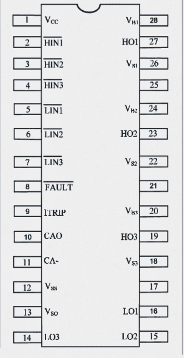
Pinout Details of the IC

The above shows the pinout diagram of the IC IRS2330 which simply needs to be connected to a set of a few external components for implementing the proposed BLDC controller circuit.
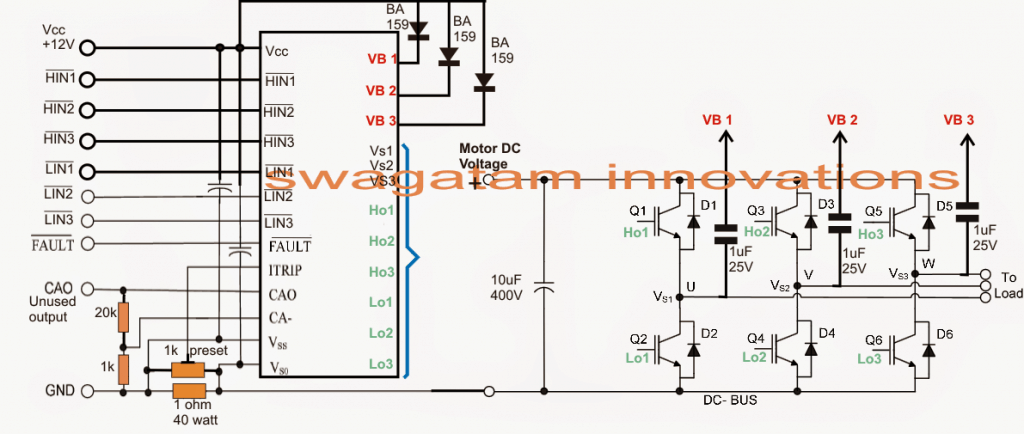
How to Configure the Full Bridge IC
In the above diagram we witness the method of connecting the IC pinouts with some external components wherein the right hand side IGBT stage shows a standard H bridge configuration using 6 IGBTs integrated with the appropriate pinouts of the IC.
The above integration concludes the output power stage for the BLDC controller circuit, the "load" indicates the BLDC 3 phase electromagnet coils, now its all about configuring the inputs HIN1/2/3 and LIN1/2/3 of the IC with the relevant hall sensor outputs.
NOT gates for Sequencing the HIN, LIN Inputs
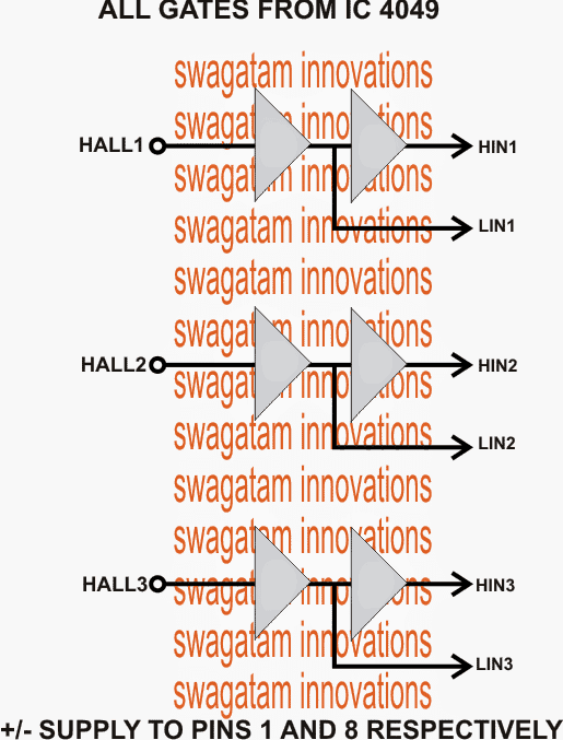
Before applying the hall sensor triggers to the driver IC inputs, it's required to be buffered through a couple of NOT gates as given in the diagram above.
Finally, the outputs of the NOT gates is integrated appropriately with the inputs of the IC IRS2330.
The negatives of all the hall sensors may be assumed to be grounded.
The second circuit which forms the main driver configuration for the proposed 3 phase brushless BLDC motor driver circuit, could be also seen having a current sensing stage across its lower left section.
The resistive divider may be appropriately dimensioned for enabling an over current protection and control over the connected BLDC motor.
For getting comprehensive details regarding the current sensing configuration and other intricacies of the whole design, one may refer to the following datasheet of the IC:
https://www.irf.com/product-info/datasheets/data/irs2330pbf.pdf

Questions & Answers
thanks for sharing knowledge
Hi Swagatam
I am looking to make a prototype dishwasher with variable temp using bldc motor do you have any plans or pcbs for this project ?
Hi Bindesh,
If you can explain the entire procedure and your requirement in details, then I may try to help!
[email protected] – can I send the details on this email ?
I would prefer discussing it through comments, so that it can be read by other visitors also. You can specify the main functional requirements, if it is possible I will try to solve it.
Hello Swagatam
Thanks for your quick help !
I suppose that the Hall wires are perhaps connected in a Star, or grounded in a special manner.
So I wrote to the factory asking the internal wiring diagram for the motor. Perhaps tomorrow morning I get it.
Independently of that, and once the three wires from the Hall sensors are clearly identified, what device would you recommend:
The IRS 2332
Or
The MC33035
Pros and cons ?
Thank for explaining that differences to us,
Kind regards
Horacio
Hi Swagatam i’m creating a motor controller but i don’t have any idea. I’m looking for a schematic diagram for motor controlloer. 48VDC supply and the BLDC motor is 600W.can you give some advice or schematic for that? thank you in advance
Hi John, If your BLDC motor is without sensors (sensorless) then the above concept could be used for driving your BLDC motor, otherwise the above concept might not work.
You are welcome Horacio,
If the hall effects are employed then the MC33035 has to be used since it is specifically designed to process the hall effect signals.
Without hall effect, the IRS2332 circuit can be used, since it can work using external independent synchronizing signals from a 3 phase generator.
Both are good, but the hall effect design is the recommended one since it will provide higher efficiency for the motor rotation.
Hello Swagatam
First of all congratulations for the great job done !
I have a new BOMA MOTOR Co bought in Chine that arrived with the controller completely damaged. I borrowed a controller from a friend and test the BLDC motor that works great.
Specifications are 48 VDC, 1000 Watt, 2800 RPM.
Motor has the three thick wires for the fields and the 5 thin wires for the Hall effect sensors.
I have followed and studied all the circuits you have published in the 11 pages of Motor Controller Section.
I see your have two approaches: one using IRS2332 plus IGBTs, the second using MC33035 plus IGBTs.
Which one you advice me for my case ?
May I get details for components whose characteristics are not listed ?
Thanks for your help, kind regards from Buenos Aires !
Horacio
Hello Horacio, the hall effect sensor is supposed to work with 3 wires for the control circuit and 3 wires to the ground.
With 5 wires I have no idea which circuit would suit your motor.
MC33035 works with 3 wires from the sensor, so it may not be compatible with your 5 wire motor.
Alternatively if you want to ignore the hall effect feedback then the 3 thick wires could be directly used with any 3 phase controller like the IRS2332
Hi,
First, thank you for all that you’ve done so far. I’m trying to use a salvaged Segway motor from an i657 as as a servo motor for a CNC machine, and I’m curios to know if you have any idea how I would wire it to your circuit. I’m getting confused because this motor manufactured by Pacific Scientific has no available data sheets. It has a PCB lead attachment with 6 coil inputs in matching sets of three wires, and what appears to be 2 matching hall sensor outputs with 7 leads each. The PCB has two 53ND12-Y relays on it, and two diodes. I’m becoming slightly frustrated with the lack of information about this motor’s control needs. I’m sorely tempted to desolder the PCB, and just get an aftermarket encoder for positional feedback. Any suggestions? Once again, thank you so much for this resource!
Hi, I wouldn’t recommend going ahead with this project if you are not sure about the motor wiring specifications. Because the 3 phase driver explained above itself is a complex circuit which will need appropriate expertise in the filed to succeed, so you must take special care to ensure everything is perfectly known before implementing this project
I’ll get whatever expertise I need. I’ve built several stepper motor CNC machines before, as well as 3D printers, foundries, cars, airplanes, rockets, and have overseen national projects for several governments. I built an integrated vehicle computer system in my offroad vehicle in 2001 that had a tiltometers, was voice activated, and would talk to me for feedback. I think I got this. I was hoping to not have to build my own controller, but since there’s no specifications available for this motor, I’ll have to reverse engineer it. Thank you for the schematics you’ve made available, I’ll just have to pull out my old electrical engineering textbooks my father-in-law gave me. I was just being lazy. There is no intellectual pursuit I’m incapable of succeeding at. If anyone wants to give help, I’ll take it, but I’m not afraid of learning what I need to succeed.
OK fine, then you can give it a try.
Thanks for allowing me to proceed. I was concerned you might not give me permission. I’ll post back in a few months when my prototype testing is completed to see if my solution meets with your approval.
No problem! Wish you all the best!
Sir anyone who provide me assemble service and modify service
sorry nobody’s within my range at the moment…..
Pls sir were do l connect the PWM controller and is it of great important?
PWM will be required for speed control only…
Hi sir, i want to do current controller for bldc motor can you suggest me an IC.
Hi varaprasanna, the following circuit has an internal overcurrent protection
https://www.homemade-circuits.com/50v-3-phase-bldc-motor-driver-circuit/
The circuit presented in the above article also has a current control through a preset
I bought a BLDC controller with forward reverse and speed control. Pot for speed control appears to be dual gang but only 3 terminals. 3K between red and black regardless of wiper position. Resistance between white and either red or black varies but is same. Gets up to 20K near midpoint then backs down. Seen this kind of pot before
yes, but this may happen, if the two end terminals of the pot are shorted, and the the response is measured across this common shorted terminal and the center terminal….
If the two pots are paralleled internally but wired opposite you would get Max at midpoint and less toward either end. But motor speed continues to increase as pot is rotated. Thanks
That looks strange, you can try removing it from the circuit board and then check its resistance values
Hi, what mosfet or igbt would you recommend for a 1000w motor
Hi, STGB20N40LZ will be good!
No I haven’t yet seen pots with such a response, the resistance should increase or decrease proportionately depending upon the rotational direction until the end point reaches, it is not supposed to change the course in the midway.
can please show me a circuit of controlling an ac motor for electric car the voltage is 230v 400amps
you can try the following concept for it
https://www.homemade-circuits.com/2017/07/universal-esc-circuit-for-bldc-motors.html
I'm using 2130 ic with same pinout as 2330. Finished testing and ready to hook up to motor. Not sure how to control forward and reverse. Any thoughts?
Thanks. I'll try that and report back
fwd reverse can be probably implemented by reversing the 3 phase input signal sequence
I bought some but didn't YET feel I could use them. I need dip chips and those are typically in other formats
you can use any type, as long as it is solderable
I'm waiting on 4049 in dip configuration. I should have been more careful to pick a config that meshes with my project boards .100 through board holes. Could use Arduino digital inputs but like your idea better. No programming!
thanks, by the way did you check the other BLDC drivers published in this blog? those surely seem to be more compact and advanced than the above concept
The hall sensors on my BLDC work like a switch. They furnish a common (closed) signal or an open. If I connect vdd (+12vdc) to 12v led then to sensor lead it lights up as motor turns
yes that's fine, you will need to configure them with the 4049 gates as suggetsed in the above article.
Irs 2330 packages not easy to connect to.
Hello. Can I use another ic instead irs2330?
yes you can replace it with any other IC having identical features….
sorry I am not good at coding MCUs, so it can be difficult from my side.
Thank you. i am working on building my own electric motor bike using 1KW BLDC motor from scratch. And i am looking for simple speed controller designs, do u have any suggestion for me to start with?
Thank you
You can try the concept explained in the following article, it's probably the easiest one
https://www.homemade-circuits.com/2016/12/3-phase-solar-submersible-pump-inverter.html
Hi Swagatham,
Liked the circuit, got the whole circuit set up.
But not sure what to give as input to Hall1, Hall2, Hall3.
Guess there should be a logic circuit, please help me with that.
Thanks
Uday
Thanks Uday, the hall sensors are supposed to be attached with the BLDC motor …however if you intended to create the signals artificially, you can do it by following the concept which is explained in the following article
https://www.homemade-circuits.com/2016/12/3-phase-solar-submersible-pump-inverter.html