In this post I have explained the making of a simple 3 phase induction motor speed controller circuit, which can be also applied for a single phase induction motor or literally for any type of AC motor.
When it comes to controlling the speed of induction motors, normally matrix converters are employed, involving many complex stages such as LC filters, bi-directional arrays of switches (using IGBTs) etc.
All these are employed for ultimately achieving a chopped AC signal whose duty cycle could be adjusted using a complex microcontroller circuit, finally providing the required motor speed control.
However we can experiment and try to accomplish a 3-phase induction motor speed control through a much simpler concept using the advanced zero crossing detector opto coupler ICs, a power triac and a PWM circuit.
Using Zero Crossing Detector Opto Coupler
Thanks to the MOC series of optocouplers which has made triac control circuits extremely safe and easy to configure, and allow a hassle free PWM integration for the intended controls.
In one of my earlier posts I discussed a simple PWM soft start motor controller circuit which implemented the MOC3063 IC for providing an effective soft start on the connected motor.
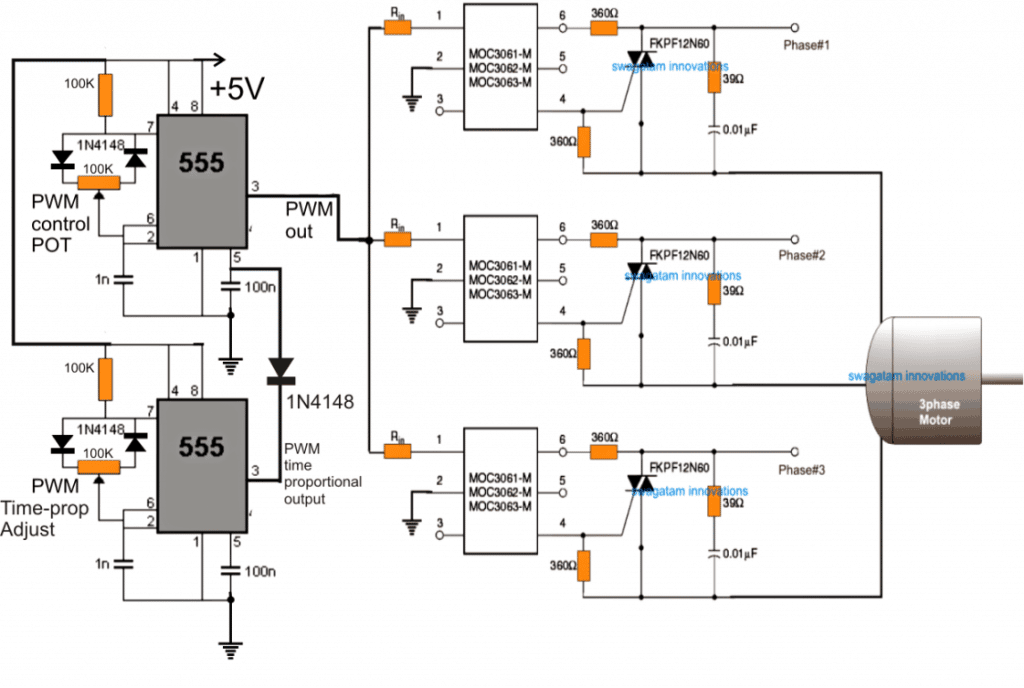
Here too we use an identical method for enforcing the proposed 3 phase induction motor speed controller circuit, the following image shows how this can be done:
In the figure we can see three identical MOC opto coupler stages configured in their standard triac regulator mode, and the input side integrated with a simple IC 555 PWM circuit.
The 3 MOC circuits are configured for handling the 3 phase AC input and delivering the same to the attached induction motor.
The PWM input at the isolated LED control side of the opto determines the chopping ratio of the 3 phase AC input which is being processed by the MOC ICS.
Using IC 555 PWM Controller (Zero Voltage Switching)
That implies, by adjusting the PWM pot associated with the 555 IC one can effectively control the speed of the induction motor.
Output at its pin#3 comes with a varying duty cycle which in turn switches the output triacs accordingly, resulting in either increasing the AC RMS value or decreasing the same.
Increasing the RMS through wider PWMs enables acquiring a higher speed on the motor, while decreasing the AC RMS through narrower PWMs produces an opposite effect, that is it causes the motor to proportionately slow down.
The above features are implemented with a lot of precision and safety since the ICs are assigned with many internal sophisticated features, specifically intended for driving triacs and heavy inductive loads such as inductions motors, solenoids, valves, contactors, solid state relays etc.
The IC also ensures a perfectly isolated operation for the DC stage which allows the user to make the adjustments without the fear of an electric shock.
The principle can be also efficiently used for controlling single phase motor speed, by employing a single MOC IC instead of 3.
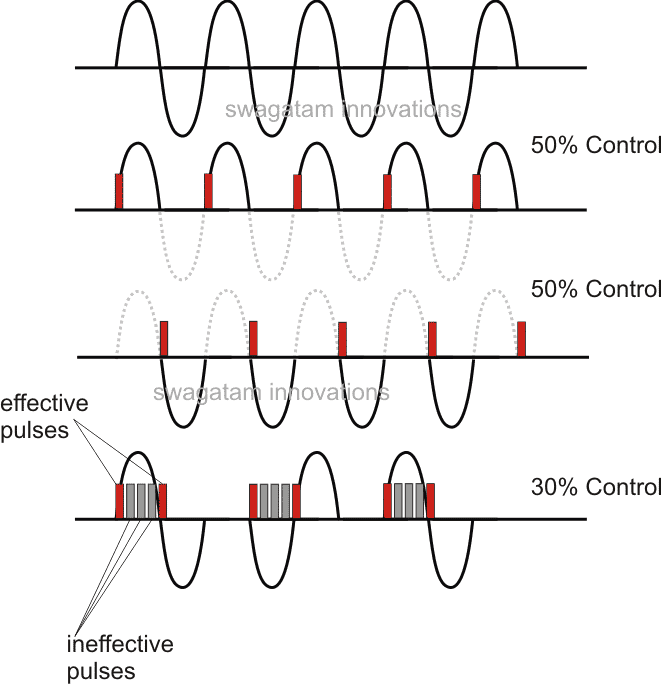
The design is actually based on time proportional triac drive theory. The upper IC555 PWM circuit may be adjusted to produce a 50% duty cycle at much higher frequency, while the lower PWM circuit may be used for implementing the speed control operation of the induction motor through the adjustments of the associated pot.
This 555 IC is recommended to have relatively lower frequency than the upper IC 555 circuit. This may be done by increasing the pin#6/2 capacitor to around 100nF.
Assumed Waveform and Phase Control using the above Concept:
The above explained method of controlling a 3-phase induction motor is actually quite crude since it has no V/Hz control.
It simply employs switching the mains ON/OFF at different rates to produce an average power to the motor and control the speed by altering this average AC to the motor.
Imagine if you switch the motor ON/OFF manually 40 times or 50 times per minute. That would result in your motor slowing down to some relative average value, yet moving continuously. The above principle works in the same way.
A more technical approach is to design a circuit which ensures a proper control of the V/Hz ratio and automatically adjusts the same depending on the speed of the slip or any voltage fluctuations.
For this we basically employ the following stages:
- H-Bridge or Full Bridge IGBT driver Circuit
- 3-Phase Generator Stage for Feeding the Full Bridge Circuit
- V/Hz PWM Processor
Using a Full Bridge IGBT control Circuit
If the setting up procedures of the above triac based design look daunting to you, the following full-bridge PWM based induction motor speed control could be tried:
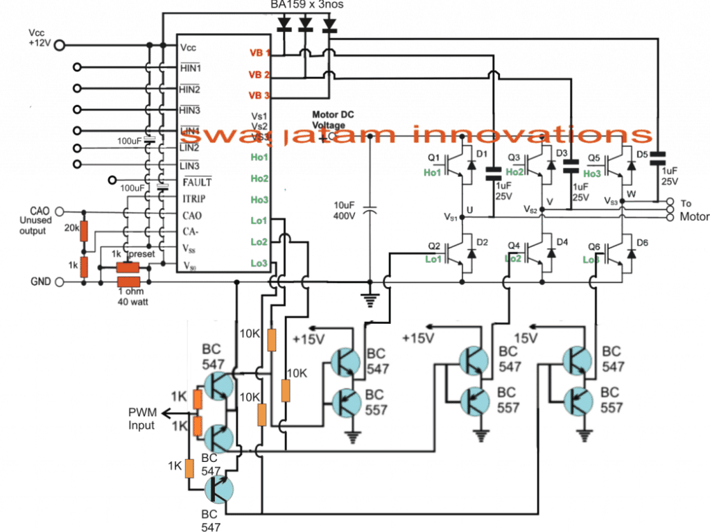
The circuit shown in the above figure utilizes a single chip full-bridge driver IC IRS2330 (latest version is 6EDL04I06NT) which has all the features in-built in order to satisfy a safe and a perfect 3 phase motor operation.
The IC only needs a synchronized 3 phase logic input across its HIN/LIN pinouts for generating the required 3 phase oscillating output, which finally is used for operating the full bridge IGBT network and the connected 3 phase motor.
The speed control PWM injection is implemented through 3 separate half bridge NPN/PNP drivers stages, controlled with a SPWM feed from an IC 555 PWM generator as seen in our previous designs. This PWM level may be ultimately used for controlling the speed of the induction motor.
Before I have explained the actual speed control method for the induction motor, let's first understand how the automatic V/Hz control can be achieved using a few IC 555 circuits, as discussed below
The Automatic V/Hz PWM Processor Circuit (Closed Loop)
In the above sections I have explained the designs which will help the induction motor to move at the rate which is specified by the manufacturer, but it won't adjust according to a constant V/Hz ratio unless the following PWM processor is integrated with the H-Bridge PWM input feed.
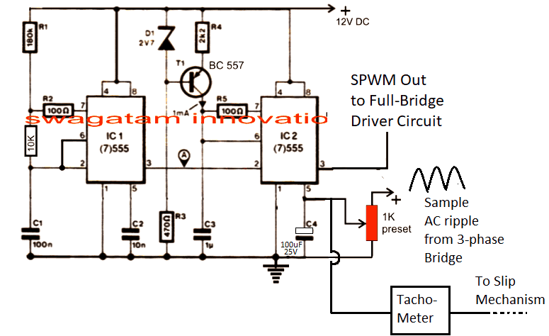
The above circuit is a simple PWM generator using a couple of IC 555. The IC1 generates the PWM frequency which is converted into triangle waves at pin#6 of IC2 with the help of R4/C3.
These triangle waves are compared with the sinewave ripple at pin#5 of IC2. These sample ripples are acquired by rectifying the 3 phase AC mains into a 12V AC ripple and is fed to pin#5 of the IC2 for the required processing.
By comparing the two waveform, an appropriately dimensioned SPWM is generated at pin#3 of IC2, which becomes the driving PWM for the H-bridge network.
How the V/Hz Circuit Works
When power is switched ON the capacitor at pin#5 begins by rendering a zero voltage at pin#5 which causes the lowest SPWM value to the H-bridge circuit, which in turn enables the induction motor to start with a slow gradual soft start.
As this capacitor charges, the potential at pin#5 rises which proportionately raises the SPWM and enables the motor to gain speed gradually.
We can also see a tachometer feedback circuit which is also integrated with pin#5 of the IC2.
This tachometer monitors the rotor speed or the slip speed and generates additional voltage at pin#5 of IC2.
Now as the motor speed increases the slip speed tries to synchronize with the stator frequency and in the process it begins gaining speed.
This increase in the induction slip increases the tachometer voltage proportionately which in turn causes IC2 to increase the SPWM output and this in turn further increases the motor speed.
The above adjustment tries to maintain the V/Hz ratio to a fairly constant level until finally when the SPWM from IC2 is unable to increase any further.
At this point the slip speed and the stator speed acquire a steady-state and this is maintained until the input voltage or the slip speed (due to load) are not altered. In case these are altered the V/Hz processor circuit again comes into action and begins adjusting the ratio for maintaining the optimal response of the induction motor speed.
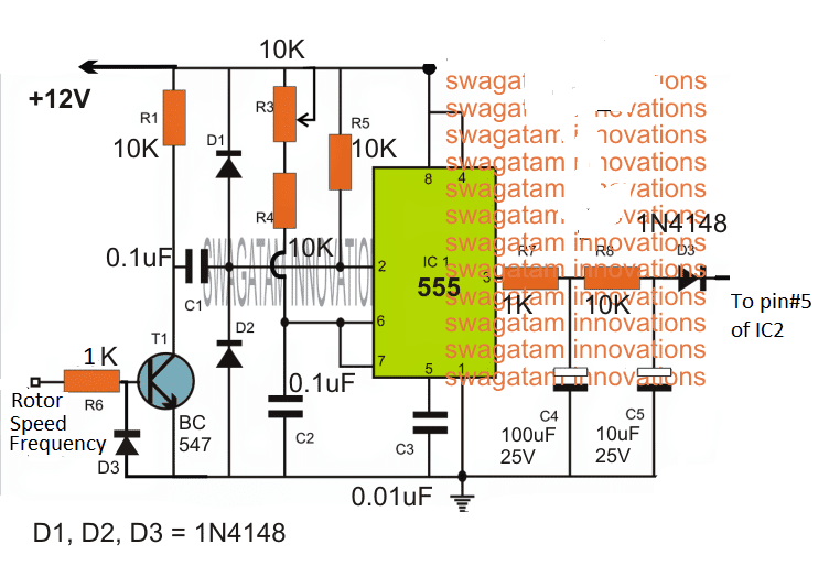
The tachometer
The Tachometer circuit can be also cheaply built using the following simple circuit and integrated with the above explained circuit stages:
How to Implement the Speed Control
In the above paragraphs we understood the automatic regulation process that can eb achieved by integrating a tachometer feedback to a auto regulating SPWM controller circuit.
Now I have explained how the speed of an induction motor can be controlled by varying the frequency, which will ultimately force the SPWM to drop and maintain the correct V/Hz ratio.
The following diagram explains the speed control stage:
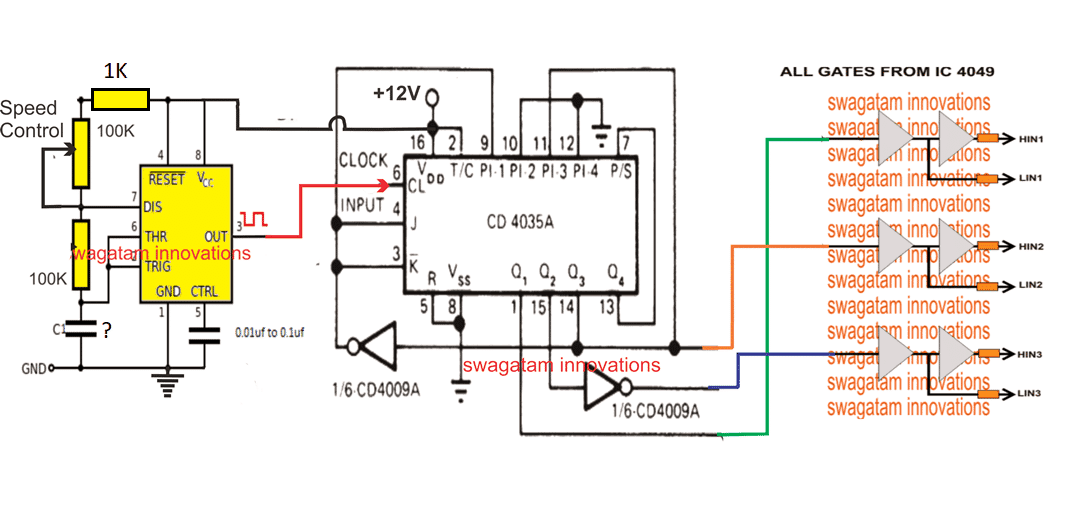
Here we can see a 3-phase generator circuit using IC 4035 whose phase shift frequency can be varied by varying the clock input at its pin#6.
The 3 phase signals are applied across the 4049 IC gates for producing the required HIN, LIN feeds for the full -bridge driver network.
This implies that by suitably varying the clock frequency of IC 4035, we can effectively change the operating 3-phase frequency of the induction motor.
This is implemented through a simple IC 555 astable circuit which feeds an adjustable frequency at pin#6 of IC 4035, and allows the frequency to be adjusted through the attached 100K pot.
The capacitor C needs to be calculated such that the adjustable frequency range comes within the correct specification of the connected induction motor.
When the frequency pot is varied, the effective frequency of the induction motor also changes, which correspondingly changes the speed of the motor.
For example when the frequency is reduced, causes the motor speed to reduce, which in turn causes the tachometer output to reduce the voltage proportionately.
This proportionate reduction in the tachometer output forces the SPWM to narrow down and thereby pulls down the voltage output to the motor proportionately.
This action in turn ensures that the V/Hz ratio is maintained while controlling the induction motor speed through frequency control.
Warning: The above concept is designed on theoretical assumptions only, please proceed with caution.
If you have any further doubts regarding this 3-phase induction motor speed controller design, you are most welcome to post the same through your comments.



Questions & Answers
In this your curcuit sir
What microcontroller is being used
Yes I designed that circuit, no microcontroller has been used, all discrete iCs.
Ok
I have a school project with same iCS but can’t seen to find it on any simulation software
Yes, I understand, but there’s no need to simulate, because as per my knowledge the circuit will surely work if done correctly and step wise. Instead of that single IC, you can consider using 3 of these ICs:
https://www.homemade-circuits.com/ir2184-and-ir21844-half-bridge-driver-circuit-diagram-working/
Sir I have many problem in phase control circuit please help me sir actually mne ek phase control krna mne ujt se v 1:1pulse transformer lga kr try kiya sir but sir nai work kr raha ਫਿਰ 555 se pulse transformer joint kiya ta k vo pulse transformer isolation krke triac ko trigger kre but impossible sir please help me sir
Hello Sukhwant, I will surely help you…please try the following circuit, it should work if you connect the parts correctly:
https://www.homemade-circuits.com/wp-content/uploads/2020/07/volatge-stabilized-dimmer.jpg
Please let me know if you have any issues with the circuit.
1. devre de 555 bloğunda oluşan sinyal frekansı kaç hertz? bu bölümü yapamadım.
The 555 frequency will depend on the value of the capacitor at pin#6/2 of the IC, which can be modified as desired…
Hız ayar potansiyometre yerine dokunma yüzeyi nasıl konur?
Adding a touch speed control can make the circuit very complex, I do not have an easy design for it…
Güzel ve basit bir devre. 555 den optokupler e giden direnç değeri nedir? Öğrencilerimle yapmayı düşünüyoruz.
Glad you liked the concept!
For a 5V supply, a 470 ohm resistor should be enough for each opto LED.
Hi
Very helpfull and simple explanation
I hope you to be glad
Thank you so much!
I am currently working on implementing SVPWM (Space Vector Pulse Width Modulation) for speed control in 3 phase induction motor using Arduino. I’m looking for a detailed circuit diagram to help me with the design and would appreciate any guidance or resources on this topic. Any assistance would be greatly appreciated!”
Hello Tathagat, I wish I could help you, however since my Arduino knowledge is not good, so it might be difficult for me currently to help you with this project. I hope you will understand and kindly bear with me…
Buna ziua domnule.Am o întrebare care nu e despre subiectul de mai sus.Exista posibilitatea de a face din 220v -380v?Daca da,as dori o schemă simpla pentru un proiect de casa,pentru a alimenta un motor de 1,5kw.Multumesc.
Hello Lacusta, the first schematic is the simplest one and should work if done correctly. There’s no other concept simpler than the first schematic using optocouplers.
Mulțumesc domnule pentru amabilitate.
You are most welcome!
Hello swagatam,
I made single phase to three phase motor controller using spwm from arduino feed to full bridge mosfet driver. So, if I want to make auto v/freq adjustment I need the circuit with 2 555, tachometer circuit, and tachometer with hall sensor and magnet attached on the motor shaft. The output from arduino will go to the 2 555 circuit and feed to the mosfet driver. So if I change the freq then the v/freq will adjust accordingly. Is this correct?
can this circuit diagram, drive up to 300kw electric motor,3phase
Hello Wira,
I will have to see the schematic to understand your concept, without the schematic it may be difficult for me to understand the working concept.
I will draw the schematic, but it is a basic circuit. I learn from your schematics and find the component available. I cannot get most of the component you use.
First i have arduino with 3 set of hi/lo pwm output with 120 degree phase shift. Then it goes to 3 pcs ir2110 to drive 2 igbt each. The output then goes to low pass filter to 3 phase motor.
The igbt power supplied from 220v ac main to full bridge recrtifier then to 450v capacitor.
I am thinking to “alter” the 3 pwm output from arduino to ir2110 using 3 of your v/freq circuit and parallel the tachometer output. I also think as alternative I also could use just 1 pwm output, and phase shifted them using opamp(also from your circuit) to produce 3 set of pwm phase shifted by 120 degree.
Then the output go to the 3pcs ir2110. The v/hz and tachometer circuit could “alter’ the pwm input to the opamp from arduino.
Yes, what you are suggesting looks good to me. It should be OK. But implementing it practically can be quite hard.
I still unsure about the concept, this is my concern:
– by tapping only the hi pwm input on i have no control on the lo input, ir2110 might turn on both mosfet and create short circuit.
– if i somehow generate the lo signal from the pwm processor, i am not sure if ir2100 will add dead time between mosfet on and off. As there is difference in the time between mosfet turning on and off, this will also lead to shorting both mosfet.
I think it is easier to use single pwm instead hi and lo. I could use fan73892 which take single ended pwm input. It also do add dead time between mosfet on and off sequence. I also will only need one pwm processor to apply the concept.
I was reluctant because i could only find fan73892 in smd package, but i already put an order on it. I think I will test the circuit without the mosfets to be sure and use lm317 output with resistor divider to simulate the tachometer circuit. I will look how pwm signal got altered by the pwm processor using a scope. This will take times as i need to build another circuit from scratch, and I could only do it when i have free time.
Anyway, thanks for your reply.
You will have to create opposite PWM signals on the Hi, Lo inputs of the IC by using NOT gates, as shown in the following figure:
https://www.homemade-circuits.com/wp-content/uploads/2022/08/3-phase-inverter-circuit.jpg
All full bridge ICs have in-built dead time adjusted, so no issues about that.
However, yes, if you have access to a single PWM input IC, then it is much better and easier.
The pwm source i use is digital with hi and lo, the not gate convert analog to digital. My idea is to add another pin outputing analog pwm, but my uno already struggling with current code.
Now, i try to use nodemcu esp32s, which is cheaper(i got nodemcu v1.1 just for $5) and much faster(12mhz vs up to 240mhz dual core) plus it got two 12bit adc(vs a 10bit adc on arduino uno). But the code won’t work with nodemcu, as node mcu did not have on board timer. Currently i am still learning the basic of using esp32.
I am trying to generate a pair of digital and analog signal from esp32. Also the analog voltage is only 3.3v which wouldn’t work with mosfet driver, but i think this could be adjusted using transistor, isolator or opamp.
With node mcu, i think i also could use it as comparator taking speedometer input as feedback.
Update: the 3phase smd mosfet driver has arrive, i have try using lan cable to convert it to dip. The wire was to big and to stiff, i will try using 24awg wire today.
Hello sir,
Myself Saikat I tried to build the circuit of speed control of 3phase induction motor using zero crossing detector. But I am unable to understand why the MOC3061 is connected with the phase using a 360ohm resistor. Please clarify it.
Hello Saikat,
The MOC3061 configuration is as per the datasheet of the IC. Please check out the following datasheet and refer to the diagram under “Basic applications”
https://www.mouser.in/datasheet/2/308/1/fairchild_semiconductor_moc3061m-1191638.pdf
Thank you sir
Can I use it to drive a 310v 160w 3-wire DC motor (U, V and W wires)
Basically, I want to drive this DC motor from 220v AC at three different speeds
You can use the mentioned motor, but the input supply will need to be 3 phase, as indicated in the diagrams. Make sure the triacs are appropriately rated.
Hi Swagatam,
I am looking for an inexpensive, straightforward way to control the speed of a 3-phase hoist motor. This motor operates a 500 kg SWL chain block with a hook on the end, and we use it to swap out heavy parts of a CNC machine.
It is a single speed hoist (6.7 m/min) and its speed is too fast for us. It can drop parts onto the concrete floor quickly. We would like to be able to halve its speed but I don’t want to go to the expense of buying a commercial VFD or similar for this simple application.
Motor specs are: 415 volt, 0.8kW, 4 pole, 50%ED, 50Hz, 2.5A, 1380 RPM
I am hoping that one of your simple circuits will do the job for us. Which would you suggest, please?
Hi Jim, I am not sure if this would work perfectly or not, but it can be tried. According to me the 3 phases can be connected with 3 identical light dimmer switches in series, and the dimmer controls could be synchronized such that they produce identical amount of control on the 3 phase lines. In this way the load could be perhaps controlled by moving the synchronized controls or the pots of the light dimmer switches.
You can initially try this with a smaller load to check the response.
Dear swagatam, I made the changes you suggested, I think.. things have improved, however, the igbts and the driver no longer burn but…. every time the dc voltage on the igbt drain exceeds 90VDC the driver goes to the “FAULT” mode and the outputs are disabled.
If I lower the voltage everything seems to work fine. Do you have any idea what could be happening?
Any other suggestions??
thanks again.
Dear Marcio, It is good to know that now the IGBTs now are not burning. I checked the datasheet of the IC IR2130, and learned that the IC will go into a FAULT mode in case it detects an over-current or undervoltage shutdown. I think in your case it could be an over current shutdown happening.
I am sure you might have wired the current detection network across the ITRIP pin of the IC. You might have to adjust the current sensing resistor values so that the IC does not go into a fault mode due to an over current sensing across this network.
Dear Swagatam, I’m Marcio from Brazil, congratulations for all your projects and for your patience in answering all your followers’ doubts, by the way, I have a doubt too and I hope you can help me.
I set up the speed control project for the 3 phase AC motor, however, I used the IR2130 with a PWM program coming from a PIC 16F628.
But, when I do the test with the AC motor (220VAC 2HP)with a lower voltage, around 45VDC everything works great, but when I apply the correct voltage on the DC bus around 320VC… Bang!!! everything explodes, the igbt, the driver etc… when I reapply a lower voltage, everything works, do you have any idea to solve this that can help me….
Thank you very much and greetings from Brazil.
Dear Marcio, Increasing the DC buss also increases the voltage spikes across the IGBTs, which is why the IGBTs mght be blowing off. Did to put reverse diodes across the collector/emitter of the IGBTs? If not please make sure to put these diodes. Also, make sure to add a 100uF/400V capacitor right across the IGBT bridge supply lines, that is the DC BUS lines. Furthermore add a 1K resistor across the gate/emitter of each IGBT.
For the driver circuit, try adding a 100 ohm resistor between the 12V Dc input and the Vcc pin of the driver IC, and add a 100uF/25V capacitor across the Vcc and ground line of the IC. Also add a 12V zener diode between the Vcc and ground line of the IC.
Thanks for your prompt reply.
I will make the changes you suggested.
Do you think pwm can generate this kind of problem??
I had difficulties to create the 120° spaced signal and I think they are not working properly… could this also be the problem? …another thing !!… does the IR 2130 automatically regulate the voltage at the igbt gate ?
I’m using IGBT silan 40n60
(VGE =~ 20V).. how do I limit this voltage??
thank you again..
I can’t say about the PWMs, if you think they are not working properly then you must correct it appropriately.
The output from the IR 2130 will be same as the voltage applied at its Vcc pin. If its is 12V then the output will be also 12V.
Dear swag
I have a car ac blower motor the driving circuit is defected. Is it posible to operate the motor direct on 12v adapter
Hello Hmoud, what is the rating of the motor, and at what speed it is supposed to rotate?
Nice post, i think i want to implement what you’ve been written here. But, i think something is missing in this part:
Here too we use an identical method for enforcing the proposed 3 phase induction motor speed controller circuit, the following image shows how this can be done:
after this paragraph i didn’t see an image.
Thank you, and glad you liked the post….actually it refers to the same diagram which is shown in the next paragraph:
https://www.homemade-circuits.com/wp-content/uploads/2016/07/32Bphase2BPWM.png
Hello I am looking for a PCB board design that can run a 1-3 HP motor it’s parameter are –
Input is 220v 50-60hz
And output is 220v three phase 200hz mr swagatam if you can help please let me know
Also I made a Proteus design but when put in load the output freq drops need help
Sorry Rajat, I do not have a PCB design for this project at this moment!