In this post I have explained a 48V solar battery charger circuit with high, low cut-off feature. The thresholds are adjustable through individual presets. The idea was requested by Mr. Deepak.
Technical Specifications
Hi Swagatam,
Thank you for UPS relay circuit.
I am trying to build it very soon. I will update you the result once i am done with that.
Next, i am very keen to build a Solar charge controller circuit for following requirement.
1. Battery shall be of 48 V (lead acid or maintenance free) with capacity go up to 48V X 600 AH.
2. Load to battery may be up to 1500 W (30 Amp at 48V)
3. Solar PV cell in series/parallel configuration producing voltage up to 60V and 40 Amps
The controller circuit is expected to perform as follows.
1. Cut off solar supply to battery when its voltage reaches approx 56V and maintain appropriate hysteresis to avoid frequent switching of power MOSFET. So the solar supply to battery would resume again only when the battery voltage reaches approx 48 V.
2. Low voltage disconnect of load from batter supply when battery reaches around 45 V and maintain appropriate hysteresis to avoid frequent power ON/OFF of load.
I will be grateful if you could help me building this circuit.
Thanking you.
Best regards,
Deepak
Circuit Operation
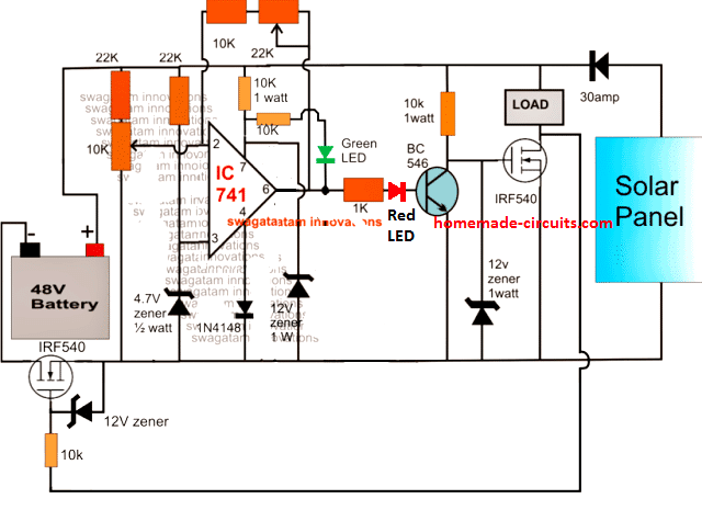
The proposed 48V solar battery charger circuit with high/low cut off feature can be witnessed in the following diagram.
The functioning of the circuit may be understood with the following points:
The IC 741 is configured as a comparator and is appropriately stabilized from the high 48V input using zener diodes and potential divider networks across its supply and input pins.
As requested, the input voltage which may be in excess of 50v is acquired from a solar panel and applied to the circuit.
The 10k preset is adjusted such that the power mosfet cuts off when the connected battery reaches the full charge level.
The 22k preset is the hysteresis control for the circuit and also serves as the lower threshold adjustment preset.
It should adjusted such the the MOSFET just initiates and switches ON at the preferred low battery voltage threshold.
Once the discussed set up is implemented and power switched ON, the discharge level of the battery drags the supply to around 48V forcing pin2 of the IC to go below pin3 potential.
This prompts the IC output pin6 to go high initiating the MOSFET connected in series with the ground rail so that the battery becomes integrated with the solar panel supply.
The above also switches ON the BJT BC546 which in turn makes sure that the associated MOSFET and the load remains switched OFF.
As soon as the battery attains the full charge level, pin2 is pulled higher than pin3 rendering the output to a logic low.
This instantly switches OFF the ground rail MOSFET and the BJT enforcing two things: cutting off supply to the battery and switching ON the load MOSFET such that the load now gets access to the supply voltages from the panel as well as the battery.
The feedback hysteresis network formed by the 22k preset and the series 10k resistors ensures that the above action locks ON until the battery voltage reaches below the predetermined lower threshold.
Circuit Diagram
Diagram
Feedback from Mr. Deepak
Hi Swagatam,
Thanks for Solar charge controller circuit.
The circuit appears to be little different than what i had requested. Let me reiterate the requirement again.
1. Solar panel should continue charging battery not beyond 56 V.
2. In the event of battery discharge, the charging process should resume again only when it reaches 48V. In other words hysteresis should be maintained.
3. Battery should continue supplying power to load when battery voltage remains in between 42 - 56V.
When battery voltage reaches 42V (due to battery discharge) the load should be disconnected from battery supply.
Once the load is disconnected, it should remain disconnected till the battery voltage reaches minimum 48 V during charging process.
Please confirm if the circuit works as above.
Implementing Window Comparator
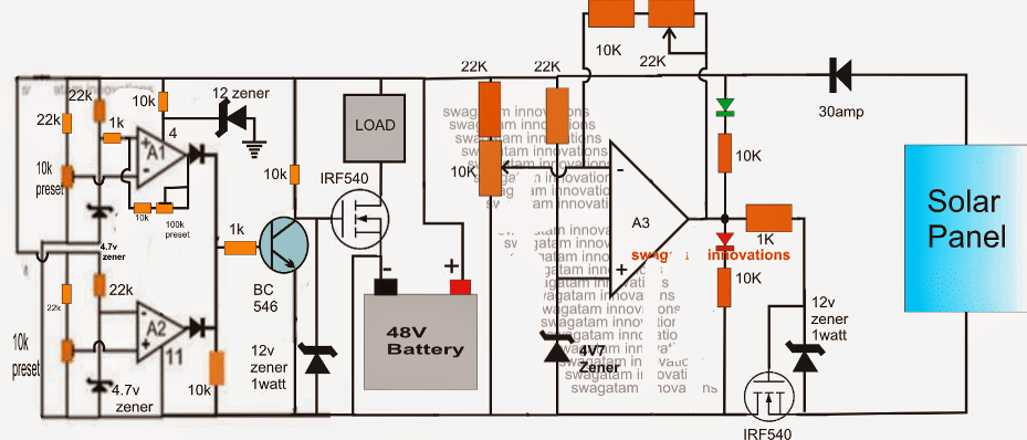
The above 48V solar battery charger circuit with high, low cut-off may be modified with these specifications by introducing a window comparator stage, as shown at the extreme left of the circuit below.
Here the opamps are replaced by three op amps from the IC LM324.
The window comparator is made by two of the 4 opamps inside the LM324.
A1 preset is set such that its output becomes high at the lower threshold level of 42V.
The 100k preset is for adjusting the hysteresis level so that the situation gets latched until 48V is reached.
Similarly A2 preset is set to make the relevant output go high at the higher threshold of 56V.
At voltages between these "windows", the BC546 remains shut off allowing the associated mosfet to conduct and feed the load with the required supply from the battery.
Once the thresholds are crossed, the BC546 is forced to conduct by the relevant opamp shutting down the mosfet and the load.
The A3 stage could also be replaced with an identical window comparator as discussed above for controlling the charging of the battery by setting up the presets appropriately, this would allow using all the four opamps from the IC LM324 and also make the operations much accurate and sophisticated.
Adding a Buzzer Indicator Stage
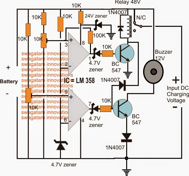
Another version of a 48V automatic battery charger cricuit using a buzzer indicator can be studied below:
The idea was requested by Nadia, please refer to the discussion between Nadia and me in the comment section for more info regarding the design
The transistor are incorrectly shown as BC547, which must be replaced with BC546 for preventing circuit malfunction and damage
How to Set up the above 48V Battery charger circuit with buzzer
Do not connect the charging voltage from the right side.
Keep the 10k preset slider arm towards ground initially.
Connect a DC input using a DC variable power supply from the Battery side on the LEFT of the circuit.
Adjust this voltage to the required potential at which the buzzer needs to get activated....as per the request it should be at around 46V
Now adjust the lower 10k preset very slowly and carefully until the buzzer just activates and starts buzzing.
Seal this preset with glue.
Now increase the input voltage to the desired high cut off level.... which is 48V as per the request here.
Next, adjust the upper 10k preset very slowly and carefully until the relay just clicks. When this happens the buzzer should shut off.
The 48V solar battery charger circuit with high, low cut-off is now set, however the value of the 100k resistor which can be seen connected between the input/output pins of the upper opamp actually decides at what lower threshold the relay must deactivate again, and switch ON the buzzer.
It's been arbitrarily fixed, you may have to adjust the 100k value so that the relay toggles only at around 46V...it may be confirmed with some trial and error
48V automatic solar battery charger using relay
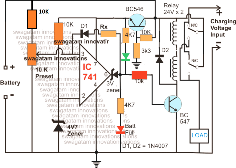
The operations involved with the first diagram above gets much simplified if a relay stage used instead of BJTs, and mosfets.
As can be seen in the above updated diagram, the relay stage is in the form of two 24V relays in series, wherein the coils are joined in series while the contacts are joined in parallel.
The sensing circuit is applied with a proportionately scaled down voltage through an emitter follower voltage divider circuit using the indicated BC546 stage for the intended battery level detection and cut-offs
The following diagram shows an extremely simple 48 V solar charger system which allows the load to access the solar panel power during day time when there's optimal sunshine, and features an automatic switch over to battery mode during night when the solar voltage is unavailable:
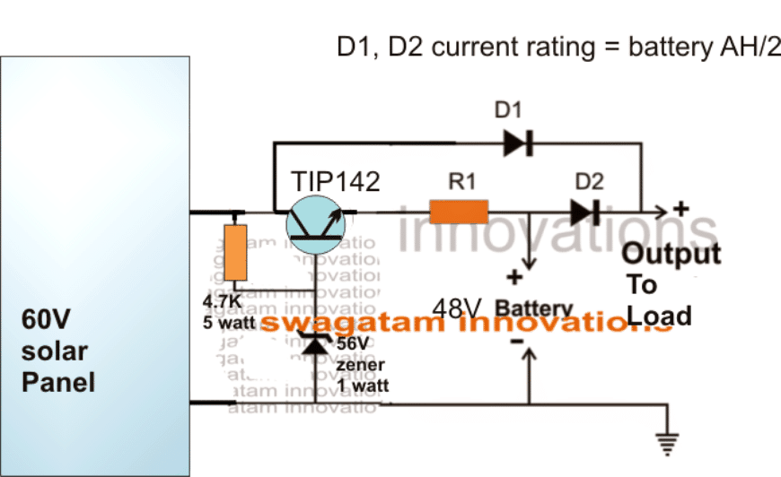
The emitter follower TIP142 ensures that the battery is never allowed to get overcharged above 55V.



Questions & Answers
Hi Swagatam,
Thanks for Solar charge controller circuit. The circuit appears to be little different than what i had requested. Let me reiterate the requirement again.
1. Solar panel should continue charging battery not beyond 56 V.
2. In the event of battery discharge, the charging process should resume again only when it reaches 48V. In other words hysteresis should be maintained.
3. Battery should continue supplying power to load when battery voltage remains in between 42 – 56V. When battery voltage reaches 42V (due to battery discharge) the load should be disconnected from battery supply. Once the load is disconnected, it should remain disconnected till the battery voltage reaches minimum 48 V during charging process.
Please confirm if the circuit works as above.
Best regards,
Deepak
Hi Deepak,
I'll update the modifications soon.
Hi
Can u pls help me modify above ckt for operating a relay once battery reaches low voltage 46v and off the relay on reaching 48v for telecom purpose ? Rgds RAMESH
Hi, you can try the last circuit from the following post:
https://www.homemade-circuits.com/make-this-48v-automatic-battery-charger/
hi swagatam sir
this is srinivas
can i use this circuit for 12 volts 300ah battery if any changes please tell me sir
thanks & regards
Hi Srinivas
yes you can use it, just upgrade the mosfet for handling upto 50amps
for 12V battery the 22k resistors may be changed to 1k
hi swagatam sir
this is srinivas
what are the value of A1,A2 conected diodes
thanks
You can use 1N4148 for the diodes, 1N4007 will also work
Hi Swagatam,
I built charge control section of this circuit but somehow it is not working. My findings are:
1. MOSFET IRF 540 remains 'ON' always.
2. when 10K POT is varied the output of the comparater A3 changes but this change has no effect on state of MOSFET IRF540.
3. Tried with 3 new MOSFET but the result is same.
My guess is comparater voltage output is not completely '0' when its state changes to 'OFF' which is very important for MOSFET to function as a switch. I may be wrong. Please suggest me what else could be wrong. Thank you.
Best regards,
Deepak
Hi Deepak,
Try connecting a 1K resistor across the gate and source of the fet and check the response.
If it still doesn't work we may have to think about using a BJT stage between them.
Hi Swagatam,
Sorry it is not working even after placing 1K resistor across G-S. I have fried almost a dozen of FET playing with circuit but to no success. Please advice me further as this circuit is bothering me a lot. Thank you.
Deepak
Hi Deepak,
an fet will fry only if its voltage and amp specs are exceeded beyond the tolerable limits.
I cannot see any possibility in the diagram for this, as all have been taken care of.
The gate and the opamp supply pin is clamped with 12V zener diodes.
the drain is hopefully not getting loaded above the rated current by the battery in your design.
so there's no way the fet can get damaged.
I hope you are testing it with a battery connected, otherwise the IC will not get activated and will provided wrong results….so a battery is a must for the initialization of the circuit.
Hi Swagatam,
One more thing. Can i use IRFZ44N instead of IRF540 because i have about dozen of new IRFZ44N in my inventory and i want to use for this circuit if it is ok. Datasheet of both Mosfet seems almost same with only difference is in voltage rating. Please advise. thanks.
Deepak
For testing sake try a BJT, for example a TIP122 in place of the fet and see the response for the same. however TIP122 can tolerate only 2amp max, so use a smaller battery for the experiment.
also connect an LED in series with its base resistor, this will give an indication of the switching action accurately.
mosfets can be tried later on.
also do not connect the solar panel or any other supply at the input….just connect the battery and check the response of the base LED.
after this you may go ahead with the input supply and proceed with further testings
Hi Swagatam,
Yes i am testing with 48V battery and before connecting Solar input (2 units of 185W, 24i did make sure that the comparator output (and also LED) changes its state when 10K POT is adjusted. Doing so confirms me that at least comparator circuit it working fine, isn't it?
After that i connect the MOSFET. But i have found one interesting thing which i have reconfirmed with atleast several new MOSFET. The MOSFET is conducting and its state becomes 'ON' even if i do not connected 'gate' to the circuit. I have reconfirmed this problem even with several new MOSFET. This is very surprising which should not have been the case. Furthermore once this happens then i think MOSFET are getting damaged one after another.
I am stuck now and wondering if this cirucuit has really been built and test by anyone in this forum. Please advise me further.
Deepak
Hi Deepak,
It seems to be a different issue, not related with the circuit.
Because if the opamp output LED is showing the correct response means the circuit is performing correctly.
The mosfet could be blowing off due a static electricity, this could happen even with a bare touch of finger on the gate, although I have never faced this problem while handling mosfets.
If you want to get away from all this mess, then I would recommend you to convert the output stage wth BJTs or with a relay…eliminate the mosfets completely from the circuit and you won't have any such problems.
I'll update the article with a BJT circuit soon…
Você teria um circuito pra 72v tipo desligar quando cair abaixo de 65v e ligar com 70v novamente ?
The last concept from the following article can be used for implementing your idea:
https://www.homemade-circuits.com/make-this-48v-automatic-battery-charger/
Hi Swagatam,
Please let me know what do I need to change in the above circuit to make it working for 24V (2 nos of 12 v @ 150AH) batteries.
Thanks for the circuit.
Regards
Gopal
Hi Gopal,
You won't have to change anything in the circuit, you can use it as given.
the supply pin resistor/zener can be eliminated if the opamps from LM324 are used instead of IC 741
Hello there,
It is requested to please help me design a circuit for 48 volts rectifier/charger to operate a buzzer on its failure, with a variable to adjust the dropout voltage. Circuit should mark the relay and sound the buzzer as soon as the charger voltage drops to 47 or 46 volts and it should unmark the relay and stops the sounding relay as soon as the voltage returns to 48 volts.
I know it is not a complex one, I have seen a circuit designed by you that is similar to my requirements, but a little tweaking is required i guess.
https://www.homemade-circuits.com/2014/04/48v-solar-battery-charger-circuit-with.html
your help in this regard is very appreciable
Thanks,
nadia
Hello nadia,
you can try the first circuit from the following article:
https://www.homemade-circuits.com/2012/08/make-this-48v-automatic-battery-charger.html
for the buzzer you can include a BC546 transistor with its base connected to the mosfet drain via a 10k resistor, emitter to ground and the relay across the positive supply and the collector of this transistor, the relay should be 48V rated as per the supply volatile.
Hello Swagatam,
I have read the thread you mentioned above, But my request here is that i need the buzzer to activate when the battery level reaches to 46v or 47v (adjustable) and it should deactivate the buzzer when the battery level regains its voltage to 48v.
can you help me in this regard please?
a detailed circuit would be v much appreciable pleassse
Regards,
nadia
Moreover load in around 10A and battery is 100AH
also load disconnection is not in the scope of my requirement. which makes it a bit easier i guess :/
regards,
nadia
Hello Nadia, I'll try to do it soon….and let you know, keep in touch in the meantime.
that would be soo kind of you 🙂
I have updated the required circuit in the above article, please check it out
Woah!!! that is so soo nice of you. I'll try to make the circuit ASA. meanwhile you canhelp me understand the physics of this circuit. I presume by seeing the circuit that it is in a comparator topology with two comparators; one for dropout voltage and other for upper thresh-hold.
You can help me understand the circuit more thoroughly as you have done in various different circuits. 🙂
Regards,
Nadia
Thanks, I have updated the setting up procedure at the end of the article, you can check it out.
The zeners at the base of the transistor can be replaced with LEDs for getting a visual indication of the proceedings, the polarity of the LEDs will be exactly opposite to the shown zener diode symbols.
well the circuit worked like charm. the feedback resistance for the required un-marking of relay was around 6.3 M ohm. but there is a glitch i must say, the buzzer starts at 46 v and stops at 44 volts. it must buzz below 46. but nevertheless it is good overall. thanks 🙂
thanks Nadia, I am glad to know it helped.
however the buzzer is supposed to start at 46V and stop at 48V (full charge) right?
I assumed you wanted to say this.
Anyway, for initiating the buzzer at lower voltages you can set the associated 10K preset (bottom opamp) accordingly so that the buzzer starts at 44V or at any other desired lower threshold..
Subhasish,
Please do it in the following way:
Initially keep the 22K perset disconnected from pin6 of the IC.
do not connect any load or the solar panel.
now feed 56V from the battery side through variable power supply unit.
next gently adjust the 10k preset such that the green LED just lights up.
this sets the high charge cut off for the circuit.
Now reduce the voltage from 56 to 44V, connect the 22K link and adjust it such that the green LED shuts off and the red LED lights up.
that's all the circuit is all set.
if the 22k preset does not work replace it with a 100k preset or a 220K.
connect a 3V zener diode at pin6 and connect the LEDs after the zener…as done in this circuit and then check the response again:
https://www.homemade-circuits.com/2012/07/make-6v-4ah-automatic-battery-charger.html
sure, please feel free to comment if you have further problems…
48 v 200 amp. Need to charge the wind turbine charge control circuit to charge the gel battery. mosfet control. when the battery is charging, the gears are connected to a separate load circuit. I would be glad if you help. Yours truly.
Please specify your exact requirements, I’ll try to help!
Subhasish, please read the previous instruction carefully….I suggested not to connect the load while adjusting the presets…here "load" refers to the battery…so do not connect the battery during the setting procedure, once the thresholds are set after that you can practically verify the results by attaching a discharged battery.
you can use a 1 watt zener diode at pin7 of the IC.
the voltage should be applied from the battery side…not from the panel side.
While setting up the circuit the input should be applied from the battery side through a variable power supply, please read the previous instructions again.
and you don't have to monitor any voltage, just monitor the LED switching as per the suggested procedures.
a 12V zener will do
when you rotate the preset as soon as pin2 voltage goes below pin3 voltage the output (pin6) will switch the LEDs from green to red…
pin3 is fixed at the shown reference 4.7 Volts with the help of the zener…so while adjusting the preset the voltage at pin2 will go below this reference 4.7V at some point…as soon as this happens pin6 can be expected to become high shutting of green LED and switching ON red LED.
Subhasish, did you set the 10k preset as per the above suggestion?
It needs to be done by applying variable supply from the battery side, NOT from the solar panel side. Unless you do this you won't be able to set it correctly.
make the second or the third circuit from the following link if you are not able follow the above circuit.
https://www.homemade-circuits.com/2011/12/how-to-make-simple-low-battery-voltage.html
BC547 is for switching OFF the load when battery volatge goes below the lower threshold
yes load and charging can be implemented together.
circuit is not practically tested, but if I were to make it I would do it without failing because I would know how to troubleshoot the small errors, if at all..
if you use a relay instead of the transistors, the same circuit can become extremely easy with a relay
I have updated the relay version at the bottom of the article, you can check it out
I have updated the diagram with all the required corrections, as far as possible.
please do it as per the new modifications….make sure you change all that's been updated in the updated diagram.
please check its datasheet to get a confirmed idea…
you can use a 100k preset in place of Rx, and adjust it for setting the lower cut off, as previously explained
The mosfets will start functioning when the supply is connected from the panel side,
after the 10k preset setting is completed from the battery side supply, connect the supply from the panel side and check all the functions
which LED do you see is ON after connecting the supply from the panel side?
Green LED ON will allow the load mosfet to switch ON and the lower mosfet to switch OFF….RED LED ON will do the opposite
..make sure to connect pin4 of the IC as indicated in the diagram.
If green is ON, then the base of BC546 will be zero.
confirm this first with a multimeter across base of BC546 and ground.
if base of BC546 is zero then mosfet gate should naturally have 12V…so it has to conduct.
check the voltage across mosfet gate and source
these will clarify everything
with your 48V batt is connected 60V input will have no bad effect on the relay…will do.
yes relay will provide you with the full 56V voltage for the batt
How's that possible? if green is ON means pin6 is zero, if pin6 is zero then from where the 0.7V get to the base?
connect another LED in series with the base of the BC546 (anode to 1K cathode to base)
and adjust preset again to force ON/OFF this LED,
now no need of putting the supply at the battery side because pin4 of the IC can access the ground from any side of the lower mosfet…so you can continue with the existing supply from the panel side.
the zener diode at pin6 was put to block this small leakage voltage so there should be no voltage at all at zener anode or may be the preset is not properly adjusted, or may be zener diode is wrongly connected.
please check all these issues…check voltage at pin6 and at zener anode
I had also suggested to connect an LED in series with BC546 base, that will instantly enable you to see whether the BC546 is switching or not
disconnect the BC546 and the mosfet gate from the anode of the zener and check the volatges again at this point.
if cathode is showing 2.6V with respect to ground then the anode cannot show 3.5V, because the 3V zener will block the 2.6V…check again after removing the above mentioned connection from the anode.
the LED will provide you the required indications…
if green is ON red will be off, and vice versa.
green ON should switch OFF BC546 and the lower mosfet… and switch ON Load mosfet.
sorry when red led is ON …the load will be OFF, because red ON means battery is low….
when green is ON then load will also be ON….green means battery is OK
when green is ON, anode of the pin6 zener should be zero with respect to ground.
increase the green LED resistor to 10K and check the response again.
I have a updated a simple circuit at the end of the article, you can try it, this will allow you to access the solar power during day time and battery during night time.
R1 will depend on the battery AH and need to be calculate accordingly
In the last circuit use an approximately 3 ohm 10 watt resistor for R1, and a BIG heatsink for the transistor otherwise the transistor will burn.
the panel should be able to provide at least 12 amps to the system otherwise the battery will not charge properly
if load is connected then the power from the panel will get divided to load and the battery…
connect a 1k from anode to ground and check again, this will help to sink the 3.5 V that you are getting at the anode of pin6 zener.
disconnect everything from the pin6 zener anode….disconnect LEDs, BC546 base resistor, and mosfet 10 ohm…and now check the voltage across anode and ground while moving the preset, check at the cathode also
OK that means your opamp is working fine.
now connect the BC546 resistor with the anode and connect an LED in series with this resistor (cathode to base of BC546 and anode to resistor)….don't connect anything else at the moment.
now again test the response of this LED by moving the preset
OK so now BC546 is switching ON/OFF correctly, check the same by connecting the "loaD" mosfet
12V zener at pin7 is fine don't change it.
check the load mosfet and after that check the lower mosfet response.
do not connect the previous LEDs (red/green) at the moment, but keep the BC546 base LED as it is.
when pin6 is zero the lower mosfet can not conduct technically.
OK change the mosfet direction and check again…put drain side to solar panel and source side to battery.
If still it doesn't work, then replace the mosfet with a TIP147 transistor and check again
sorry not TIP147, it should be TIP142
…correction:
changing the lower mosfet direction will not produce 48V for the battery…so please don't do it.
try a BJT such as TIP142 that will clarify the situation immediately
Don't try the TIP142 option yet.
first try the folowing modification.
remove the gate the lower mosfet and connect it with the DRAIN of the load mosfet.
But make sure that you change the gate 10 ohms with a 10K resistor…and connect a 12V zener across source and gate of the lower mosfet (anode to source)
this will definitely help the lower mosfet to switch ON fully while the load mosfet is switched OFF…and vice versa
I'll try to do it tomorrow
It's been updated, please see the second diagram from top
when BC546 is ON, the load mosfet will be OFF, and then the drain of load mosfet will have 56V or whatever is applied from the panel and this voltage will reach the battery side mosfet to switch it ON.
check your BC546 base LED while moving the preset…whenever the LED is ON, load mosfet will be off and voltage across its drain and ground will be 56V
MAKE SURE TO CONNECT A LOAD, OTHERWISE THE DRAIN WILL ALWAYS SHOW 0V
or connect a 22k permanent resistor between drain of the load mosfet and positive
OK, so now both the mosfets are switching correctly with the second circuit.
but 30V cannot appear across the load while the load mosfet is OFF.
check the voltage across gate and source of the load mosfet when BC546 is ON, if it's zero then the voltage across the load should be also zero.
48V motor can be operated with a 54V no problem, but not above this.
for current control use a 5 ohm in series with the battery positive….but according to the calculations this needs to be rated at 500 watts so that may require it to be built using a 2mm iron wire wound over a ceramic former…..keep winding and checking the resistance until you see 5 ohms on the meter.
that is perfect
put the meter prods right across the 22K resistor or the load and see the reading
it should be 0V when gate/source of the mosfet is zero
use R1 = 5 ohms 500 watt
D1/D2 = 20 amp diodes
use a large heatsink for TIP142
put the meter prods right across the 22K resistor or the load and see the reading
it should be 0V when gate/source of the mosfet is zero
then either your load mosfet is faulty or your meter is faulty.
connect two 24V bulbs in series in place of the load (22k) and see the response.
in the last circuit in the absence of sunlight, the battery will operate the load regardless of the battery charge condition, meaning even if the battery is low still the load will be operated..
disconnect the load wire from the drain of the load mosfet and connect it with the battery negative, do it while the BC546 is ON…when BC546 is switched OFF connect the wire back to the drain.
keep the 22k across the load mosfet drain and positive, otherwise the battery mosfet will not conduct..
i try looking at net how i can adjust power toroid transformer come out 52V and stepper motor driver max have 48V how adjust volt to down. and thats have only site were have about same. what i need do i can use thats schematic to my cnc machine 10amp power supply ? need adj,down 57V to 48volt,
transformer go out about 52V after 20 000uf capasitor have 57V and stepper motor driver need only max 48V how drop volt ?
To drop 52V to 48V at 10 amps you can use series diodes rated at 20 amps each….use 7 diodes in series with the positive supply line of the 52V , the output will be a reduced 48V approx
how if made big current transistor (and volt) use etc,tip 142 and connect to positive line 1-5 transistor and 1k resistor base and potentiometer 10K adj,volt can working ?
you mean configure am an emitter follower as done in the following article? yes posiible
https://www.homemade-circuits.com/2015/03/100-amp-variable-voltage-power-supply.html
Hello Swagatam,
I am a reader of your blog, and i am dumbfounded with your amazing ideas. Can you help me build a battery charger with the following feature, i am new to electronics hardwaring:
1. Over current protection
2. Over voltage protection/ cutoff (Maybe at 15V)
3. 12V SLA battery
4. Under Voltage protection/ cutoff (Maybe at 10.3V)
5. As much as possible, the battery should remain at approx 12V
6. Fault protection
7. Fast Charging
I have a 12V SLA battery but i don't know its capacity (AH), please help me.I'll be using this for my inverter.Hoping for your positive response. Thanks
Thank you Jade,
I have already included and explained all these concepts in websites, you just have to use the search box given at the top of the site to find these.
as an example you can also refer to this post which includes almost all these features in it:
https://www.homemade-circuits.com/2012/10/make-this-3-step-automatic-battery.html
Hi Swagatam,
On the last circuit diagram, you have mention that D1 & D2 current rating = Batt Ah/2. Assuming I have 4 units of 12V, 200Ah Batt (48V, 200Ah) what would be the current rating for D1 & D2? And what is the value of R1 in between TIP142 emitter and D2?
Thank you and looking forward to your reply soon.
Best & Regards,
Dwines
Hi dwines, Actually it should be (Battery charging current) x 2
so it should be preferably rated at current twice that of the preferred charging current.
for 200AH, the charging rate could be around 30 amps, so the diodes could be rated to handle 60 amps, although slightly lower values could be also tried.
R1 decides the charging current for the battery, you can use Ohm's law to determine its value
Hi Swagatam,
Thank you & I really appreciate your help.
Dwines
Hi Swagatam,
I wonder if you can help me again with regards to switch-over circuit. Two batteries (48V, 200Ah) will be charge from solar. Here is the scenario; "Batt A" while on use "Batt B" is being charge from solar and will automatically stand-by when full charged. And when "Batt A" is at low charge (assuming 40V) "Batt B" will automatically switch-over and "Batt A" will be charge from Solar while "Batt B" is being use. And vice-versa, when "Baat B" reaches 40v "Batt A" will take-over and "Batt B" will be charge.
By the way, this is for my project supplying My 12KW, 48Vdc Inverter. It is like having two source of 48Vdc supply that will automatically switch-over when the other group reaches 40Vdc.
Thank you and hoping for your response soon.
Regards,
Dwines
Hi Dwines, I already have a couple similar designs in this website, you can find them below:
https://www.homemade-circuits.com/2013/08/automatic-dual-battery-charger-with.html
https://www.homemade-circuits.com/2014/05/twin-or-split-battery-charger-circuit.html
for making them compatible with 48V you may have to supply the IC circuit from a 7812 IC, and add additional 22K resistors with the existing resistors.
…sorry, 22K resistor will be required only with the preset upper terminals which may be disconnected from its existing position and separately connected with 48V battery positive for the sensing
Swagatam, what would need to be changed in order for the circuit to handle more amps?
you can achieve it simply by upgrading the mosfets with higher amp rating mosfets
thanks Swagatam
Hello Swagatam,
I forgot to ask you if it would be possible to add a equalization stage with a led and a switch to your circuit?
Regards,
Neo
Hi Neo, I did not understand what you meant by equalization stage, please elaborate a little more.
Swagatam,
Equalizing is an overcharge performed on flooded lead acid batteries after they have been fully charged. It reverses the buildup of negative chemical effects like stratification, a condition where acid concentration is greater at the bottom of the battery than at the top. Equalizing also helps to remove sulfate crystals that might have built up on the plates. If left unchecked, this condition, called sulfation, will reduce the overall capacity of the battery.
Thanks Neo, yes I know about it, I got confused because I started imagining it to be a circuit related term, but actually it's a battery related term.
Equalization is not an everyday requirement, rather it's maintenance process that needs to be done occasionally.
The circuit already has an overcharging facility, in fact it will overcharge the battery slightly each time it's connected. The threshold can be tweaked by the user by simply adjusting the 10k preset of the opamp. so it can be adjusted at 56V.58V, 60V or any other level as per the user's preference.
The circuit can also be forced to fluctuate between a high charge cut off and a quick restart as soon as the battery voltage goes down only by a few millivolts. This can be done by appropriately selecting the feedback resistor or the hysteresis resistor.
Ok Thanks a lot Swagatam,
I'm going to build this circuit your the one that has the buck converter.
What one would you recommend, my batteries are 48v the solar panels are 62v and the
amps are 50+.
Great work your doing here by the way.
Regards,
Neo
You are most welcome Neo,
are you referring to this circuit?
https://www.homemade-circuits.com/2016/10/mppt-circuit-using-lm317-ic.html
By the way if your panel is 60V and the batts are 48v, you wouldn't require anything complex for charging, a current controlled full-charge charge cut/off stage in the middle will be just enough to charge the batteries at maximum efficiency, although this would happen only as long as the panel voltage is above 55V
Swagatam,
this is the one https://www.homemade-circuits.com/2014/11/self-optimizing-solar-pwm-charger.html
you see I have three arrays at 62 volts 50+ amps each so want to build the right circuit for each array.
Thanks
Neo
OK, you can build it, but according to me when the panel voltage is close to the battery voltage you don't have to involve complex control for controlling, which can actually do the opposite and make the system inefficient,
I would suggest you to simply connect the loads directly with the panel through isolating diodes and if required with separate current controllers
Thanks Swagatam,
So this one– 48V Solar Battery Charger Circuit with High/Low Cut-off.
or this one–Self Optimizing Solar Battery Charger Circuit with Buck Converter.
I don't really want to baby sit the batteries that is why I want a circuit that will have full control, if that makes sense, lol
Neo
Neo, the first module from the following article will be compact and ideally suited to your need.
https://www.homemade-circuits.com/2012/08/make-this-48v-automatic-battery-charger.html
a buck converter type of charger will not help much considering that the difference between your panel voltage and battery voltage is not large, however if your panel current is significantly higher than the combined battery current then you may consider employing a boost converter type of self-optimizing charger, which will ensure a sustained supply even while sunlight is not at its peak level.
Okay Swagatam,
Hey thanks for all your help really appreciate it.
Regards,
Neo
thanks Neo, it's my pleasure!
Hi, Swagatam, sir please I need a circuit for 12V/60A solar charger controller for my project.
Please sir I will be glad if you help me
Hi, you can try the following circuit and modify it suitably to fulfill your requirement
https://www.homemade-circuits.com/2015/05/5v-pwm-solar-battery-charger-circuit.html
Hi sir thanks for the post am learning alot of things now.
sir i would want to charge 6 batteries in parrel each battery is rated at 12v/100Ah wat can i do with the circuit
Thanks Olupot, if the batts are in parallel then the above circuit cannot be used, but if they are in series then you can definitely use any of the above concepts…
thanks alot sir i am now going to use the circuit with two 24v relays to charge my batts but need some clarification on the value of resistors marked Rx,4k7, and 3k3 .the rest i have them with me thanks very much for your time in helping me
10K/3k3 decide the stepped down voltage level produced at the emitter of the BC546 for supplying the IC changing these will change the supply to the IC side.
4k7 is the LED limiting resistor.
Rx determines the activation of the relay at a given lower battery thershold, you will need to select this resistor through some trial and error by experimenting at what lower threshold the particular resistor value resumes the relay back into the charging mode.
hello sir once again want some help i am placing a 10k pot to replace Rx and can i use the same circuit as a 24v charger thanks
OLupot, you can use 10K for Rx, but 10K looks very small and the lower threshold might trigger very late, may be after the battery has drained to less than 60%…so the value should be adjusted with some trial and error….or you can refer to this article for the formula:
https://www.homemade-circuits.com/2017/01/universal-battery-charger-circuit.html
hello sir want some help once again i am placing a 10k inplace of Rx and can i use this circuit as a 24v charger thanks
yes you can use it for 24V application
hello sir want some help once again i want to place a 10pot in place of Rx. and can i use th circuit as 24v charger to charge a 24v battery. thanks
I have already answered this, please check your spam folder in your email for the replies
hello sir i have sucessfully built the circuit with out any problem but now am left with doing the final setting regarding high and low batt cut off what should i use for testing the all thing and the function of the upper green led and lower red led. thanks very much
Olupot, until you have completed the setting up procedures and tested it correctly you cannot say you have achieved success.
1) replace Rx with a 220k preset, an set it at the least or zero resistance.
2) keep the 10k preset slider to ground.
3)now apply maximum full charge voltage to the circuit.
4)adjust the 10k preset slowly until the relay just clicks ON.(RED LED ON, Green OFF))
5) now reduce the voltage to the lower threshold level, and start adjusting the 220K preset until the relay clicks OFF in the charging mode (Green ON, red OFF)
hello sir when a put on max voltage and all preset at zero resistance the green led is lighting and the relay is on as long as green led is lighting but red is off now when i vary the 10k the red turns on but green does not go off like that and relay even turned on
Olupot, both LEDs can never be ON together, did you connect the output zener correctly?…check the voltage after the zener and make sure it switches from zero to supply and vice versa during the preset adjustments…..or you can try increasing the zener value to some higher level in order to block any leakage from the IC output.
keep Rx disconnected while confirming the LED actions.
make sure the opmp IC is getting the correct supply, not exceeding 15V
there’s one correction to be made in the 2nd last diagram…. 10K preset upper end must connect with the battery positive….I’ll correct this in the diagram shortly
hello stil disturbing the green led and the relay are not going off even when i set the red led to light green remains on and relay keeps on meaning its always on charge mode
i have done all u said regarding the circuit thanks
Olupot, you did not do what I told you to do.
did you check and verify the voltages with a meter?
you will have to understand the concept thoroughly to make it work correctly, and it’s too easy.
the opamp is configured as a comparator.
in this mode, when voltage at pin#3 is higher than pin#2 you get a supply level voltage at pin#6.
conversely, when the voltage at pin#3 is lower than pin#2 then you get a zero at pin#6.
Based on this principle the entire circuit is designed to work and cut off.
so please check the above procedures and make sure your IC is performing as per these specifications.
thanks sir the system has responded well. i had to replace the ic with another new one and now and geting also a new 24v relay in place of other one and then do the final testing will update you sir thanks for your great time and quick responses
That’s great Olupot, wish you all the best!!
Dear Swagatam,
I want to use 48V automatic solar battery charger using relay circuit.
But I need to charge 4 x 50A battery with constant 3 Ampere.
How can we add current limit to this circuit.
Best regards,
Kaya
Hi Yilkaya,
for getting a current control feature, you can upgrade the circuit as per the last concept from the following article
https://www.homemade-circuits.com/make-this-48v-automatic-battery-charger/
Sir I again request u to please help me in making this 48 volt current controller . I have 48 v solar system in my house with 3.6 kw inverter and 150 ah x 4 batteries.
Will thanks a lot.
Labh, you can try the second diagram from the following article
https://www.homemade-circuits.com/make-this-48v-automatic-battery-charger/
Rx = 0.6 / 60 = 0.01 ohms, wattage = 36 watt or 50 watt will be good.
How to reples 48v contactor to 12v
you will need a separate 12V supply for the relay
Hello sir,
You are doing a wonderful working by helping thousands.
I am Deepak Patel. Can you please help us by providing a circuit dig. of 48V fast charger for charging a set of four batteries of 12V (120Ah) each. Circuit should also display the status of battery also (if possible).
Thank you
Waiting for your reply.
Hello Deepak, you can try the following concept:
https://www.homemade-circuits.com/fast-battery-charger-circuit/
For converting it into 48V please add 22K resistor in series with all the preset positive side, and 10K for the zener resistor.
Also join the supply pin through a 10K resistor to the 48V line, and add a 15V zener across the supply pin and ground of the IC (Vcc and Vss).
Change all the relays with 48V relay.
For LED indication add LEDs in series with the transistor base resistor of all the op amps. The base resistor should be 10K
Hello Swagatam, thank you for the “48V Solar Battery Charger Circuit with High/Low Cut-off” and I am going to try it out. Only one thing I am much more conservative about the “lower” limit voltage level when the load must be cut-off i.e. it must be when the battery voltage drops to 50 volts and not 42 volts on the battery. Can this be adjusted via the 220K ohm pot ? or can this be made permanently into a fixed value resistor ? Please may you advise as I am not planning to change its value.
Hello Dhoods, yes you can use A fixed resistor across the pin6 and pin2 (low cut off) but this will need to be selected by some trial and error method.
I have changed the diagram a little to make it easier to construct and understand.
Hello friend,
I am Kamlesh Jain, we had already discussed few circuit in past, today once again i need favor from you, few month ago, i bought self balancing scooter (Hover-board) for my son, and due to high voltage fluctuation in our area, the charger of the scooter dead, the charger output is 42v 2a. I want to make the same for charging scooter. please help me to build one. Better if you help me to build transformer less because i do not want to build bulky with transformer, i hope you will help me again. Thank you.
Hello friend, I think you can try the following design, but the trafo winding is critical, a little inaccuracy can result in the transistor blowing:
https://www.homemade-circuits.com/32-v-3-amp-smps-led-driver-circuit/
you can modify the 32V to 42V by adjusting the feedback components
Hi Swagatam,
I need a circuit diagram of 48V, 160Ah Li-ion Battery from 230VAC input. Kindly help
Hi Sujit, you can try the 3rd circuit from top, from this article
https://www.homemade-circuits.com/make-this-48v-automatic-battery-charger/
for 100 amp you will have replace the mosfet with a 150 amp mosfet
Swagatam, what changes would I need to make to set the auto on off circuit to 120v nominal battery voltage ? Would the resistor values have to go up or just the wattage rating for resistors loaded by zener diodes . I’m looking at a 120v nominal lead acid pack being charged Via solar panels with a peak efficiency voltage around 36v @ 8 amps thinking 4 panels in series for 144v nominal and around 170v peak.
Adam, this circuit may not be applicable for 120 V battery, instead you can try the following concepts:
https://www.homemade-circuits.com/high-voltage-360v-battery-charger/
https://www.homemade-circuits.com/220v-lithium-ion-battery-bank-charger/
Hi Swagatam – your’e are a busy designer, I have been looking at your designs and would like you to point me to one that will help me with….
I want to charge two LiFePo4 batteries is series ( max 7V) with 8 – 12 volt in put from solar panel, should have prog resister for current and adjustable out put voltage and cutoff for over voltage.
I will be using a step down from 7 v to 5 v for remote use.
No problem Leium, although there are plenty of designs which could be effectively aplied for your requiremenet, I would recomend you to try the first circuit from the following article, and check if that works:
https://www.homemade-circuits.com/battery-current-indicator-circuit/
let me know if you any any further help!
Thanks, have printed the circuit and will see if I can use it. I also needed the charger to operate between 2.4 volts disconnect load and 3.6 volts disconnect solar charger. Have see some with relays but would rather use FET or alike. Thanks again, your busy man, Swagatam.
You are welcome Leium, i wish you all the best with the project.
Yes this will be cool, when I saw 48 volts I was not thinking I could use it on 3 volt system, but changing some zener and resistors should get me where I want to be. Will spend the day pondering over the changes and tackle this project head on. Now with this virus, I can’t get spares or import what I need so I have to build , like the good old days. – much appreciated.
You are welcome Leium!
Sr good evening please i see 12v 24v 6 60v battery charger control board charger power supply circuit diagram, how does it work.
Hi, please show the schematic
I have to design a battery charger to charge 48V lead acid battery from solar. Actually i have to design this for my final year project (Solar Electric Car) while considering state of charge (SOC) and depth of discharge (DOD).
Then which circuit is best in my case.
I hope you will help me.
Thanks in Advance
If you are referring to a circuit that would indicate the DoD of the battery, then I don’t I have the circuit with me at the moment. If the battery voltage corresponds to the DoD, then probably a voltmeter can be used to translate the discharge voltage to DoD.
Here’s one design that you can try modifying for your requirement:
Precise Battery Capacity Tester Circuit – Backup Time Tester
If i do not consider DoD then which circuit would be best ?
It will depend on the required specifications. Your battery can be charged by simply connecting a low current 56V source to it, without any issues, and it can be also charged with many facilities such constant current, constant voltage auto cut off, float charge etc. if faster charging and guaranteed safety is intended.
You can read the following article for detailed info:
Lead Acid Battery Charger Circuits
Thank you
Hi Swagatam,
Do you have any designs at hand for a 48v lead acid battery balancer? This would be used in solar systems so need not think of power being wasted.
Thanks in advance and helping us all here.
Hi Joe, I do not have a balancer circuit at this moment, but you can try one of the circuits available online, such as this:
https://www.mouser.in/datasheet/2/609/3305fb-1271443.pdf
Hello, has access to several 48V Lithium batteries. Old electric car batteries.
12 cells with 4 temp sensors mounted, and BMS cards.
Unfortunately, it is not possible to use existing BMS cards as it is not known how to communicate with them. (Maybe someone has solved the problem, battery packs come from a BMW i3). My problem is how to find a solution when BMS cards are necessary.
Since I have access to several packages, it would be good to have a solution where several packages can be connected in parallel for greater effect.
These battery packs should, if possible, be used in a solar and wind solution.
Hello, A BMS basically comes with a few crucial features:
1) Constant voltage, and Constant Current
2) Auto full charge cut off
3)Temperature compensation
4) Trickle charging or float charging, for lead acid batteries.
5) Prevent self discharge
All these could be easily designed using discrete components, like ICs and transistors.
Dear, Swagatam, I have installed a 12 volt emergency lighting system from the 40 Amp lead acid group using your ideas. It works great. First of all, I want to start off by thanking you. I like your diagram above, which cuts in -low/high-voltage. How can I use this circuit in 12 Volt 6o Ampere batteries? I would appreciate if you let me know how to make a change. Greetings and my regards. Mehmet Ovacikli
Thank you Dear Mehmet, I am glad my circuits are working for you!
I have an exclusive article on high low battery charger circuit, which you can read in the following link:
https://www.homemade-circuits.com/opamp-low-high-battery-charger/
You can use one of these concepts for building your battery charger.
You can also try the following concept;
https://www.homemade-circuits.com/regulated-car-battery-charger-circuit-for-garage-mechanics/
Hi Sir,
Want to ask question about the circuit under the section “Implementing Window Comparator”, about the 2 LEDs at the right hand side. Because when I think about the operation of the circuit, I suppose now battery voltage is below 56V, let say 55V, the op-amp A3 should output 12V, then both green and red LED ON. Or now battery voltage is 56V, the op-amp A3 output 0V, then both LEDs OFF.
So both LEDs will ON or OFF at the same time. Am I wrong, because want to know about what the 2 LEDs want to indicate.
Thank you very much.
Hi Tommy, no both the LEDs can never be ON. Because when suppose the op amp A3 output is high, it will make the junction of the two LEds high, so the upper LED cannot light up, because now both cathode and anode of the upper lED is high. But the lower LED will light up because its anode is now high, and the cathode is grounded.
Similarly when the A3 output is low, the lower LED will not be able to light up because now both its terminals are at low, but the upper LED will light up because its anode is connected to the positive line, and the A3 side cathode is low.
However, the LED which is supposed to be completely switched OFF may show little illumination due to a leakage voltage from the op amp output, to prevent this you can add a 1N4148 diode in series with each LED
Hi Swagatam,
I came across your designs and they are really cool. Thanks for sharing your knowledge for free with the world. Such people are rare these days.
I’m looking for a multi output 48v lead acid charger/DC ups. Outputs being 48v (2A least),12v (15A), and 5v (8A). I understand placing buck converters at 48v load for each output will work as well. But will it be efficient? I’m also interested in adding a coulomb counter for the battery, with a digital display to show input voltage (230v) and all the outputs in an 1136oled display. We might have to work this through using a atmega integrated into the circuit at one point. I’d be greatful if you can integrate all these into one circuit if possible. Let me know if time permits.
Thank you Don, I truly appreciate for kind feedback!
yes buck converters will be efficient. If you don’t want to use buck converter then you can use a transformer with the respective voltage taps and individual regulators.
My microcontroller knowledge is not good, so it can be difficult for me to design an Atmega based circuit.
Hi Swagatam,
Just thought of a cool name for your company if you ever planning one (like Adafruit or Raspberri Pi) – SWAGTronics.
Anyway, the atmega integration is me being overly enthusiastic.
I have a few questions regarding all of these SLA battery charger designs. Have you considered trickle and float charging the batteries because linear charging is going to reduce the battery life time by few years.
Thanks so much Don,
that indeed looks a cool name for my website company. I am worried somebody else might steal this name quickly.
Regarding your question, so far I haven’t included trickle charging or float charging in battery charger diagrams, since these can be easily added to any existing auto cut off battery charger circuit simply through a bypass resistor. The resistor should be added across the cut-off relay so that the current starts flowing through the resistor to the battery once the relay is cut off. This resistor must be calculated such that the current through it just manages to prevent self discharge of the battery while it is idle and disconnected from the charger.
Thanks Swagatam, cheers for that!
Hello sir swagatam,help me out with a circuit that has both trickle charger and a float charge for charging 4 numbers of 12v/200ah which is equal to 48v. Inshort,i need a charger that can charge this batteries to full charge without overcharging and at the same time maintain the charge in the batteries. I would like a charger that once i connect on power,no unplugging. Let it be self regulating
Hello Evans, you can try the first circuit from the following article. You can connect a 1K 2 watt resistor between the drain/source of the mosfet, this will take care of the float charging or the trickle charging.
https://www.homemade-circuits.com/make-this-48v-automatic-battery-charger/
That’s great Sanjaya, glad it is working good.
The maximum input DC to a 48V battery should not be more than 58 V. So you can adjust the solar panel output to 58V DC.
Hi,
I want a 48 volt battery low voltage alarm circuit which output operate a 12 voltage relay when battery gets below 42 voltage.
Can you suggest me a circuit diagram like this comparator circuit.
Hi,
you can try the following design:
https://www.homemade-circuits.com/wp-content/uploads/2022/11/low-voltage-alarm-for-48V-battrey-charger.jpg
this schematic what part changes for solar panel 50volt
makingcircuits.com/wp-content/uploads/2017/04/SolarBatteryCharger.gif
Use transistor BD139, relay = 48V relay, battery = 48V, replace 270R with a 1N4007 diode.
thank you for answering me.if I use a battery 12 volts will be the same
For a 12V battery the circuit can be exactly as shown in the previous link. However, the 270R must be replaced with a 1N4007 diode.
thank you very much for your help and see you next schematic
Thank you, Sir. If I want to build it with a 20V solar panel and a 12V battery, what should I change in the circuit?
Hi Aulia, you can try the last circuit, with the following modifications:
Remove R1, replace the zener with a 15V zener.
Thank you, Sir. Is the 54V zener diode replaced with a lower voltage zener diode?
No problem Aulia,
That’s correct, you will have to replace the 56V zener diode with a 15V zener for your 12V battery. Also, the 4k7 or the 4.7K resistor does not need to be a 5 watt resistor, it can be a 1/4 watt resistor.
Oke Thank you Mr. Swagatam
No problem Aulia!
Hi Mr.Swagatam, If I want to create a cut-off system for a 12V lead-acid battery with a PV output voltage of 13-20V, which circuit should I use?
Hi Aulia, I would suggest you to try the LAST circuit from the following article.
https://www.homemade-circuits.com/opamp-low-high-battery-charger/
Hi Swagatam, thank you for the above. Is the above also compatible with Lithium battery packs? Can you suggest what changes to be made to the above for 60 V and 72 V battery packs (Lead Acid and Lithium)?
Hi Rajan,
Yes the above designs can be used for charging Li-ion battery after appropriate settings, however i would recommend you the LAST circuit from the following article:
https://www.homemade-circuits.com/make-this-48v-automatic-battery-charger/
This circuit is easy to configure and very safe for charging all types of batteries.
Thank you for the reply. I will check it out. Just wanted to know what modifications to be made to charge 60 and 72 v battery packs?
You can use the same design which was suggested by me in the previous comment, with the following modifications:
Replace BC546 with TIP122
Adjust the TIP36 base resistor and Rx current limiting resistor as per the required charging rate for your battery.
Very many thanks, I will try it out.
Just curious to know, in your introduction you say you area manufacturer. So do you manufacture PCBs? If yes, I would like to discuss some business opportunities with you. If no, can you share info about some PCB manufacturer who can print boards in a small quantities?
No, I don’t manufacture PCBs, I had the contact numbers of a few PCB manufacturer in Mumbai long back about 10 years ago, but I seem to have lost them, and don’t have them now.
Nevertheless you can easily search online and you should be able to find plenty of PCB manufacturers who will do the job for you.
Thanks, I found one.
Sir I have brought Some of its Component, I have put 12v Battery instead of 48 and 6v solar ponal instead of 56v and please tell what are the modifications that i have to make in order to make the circuit working properly and as a kind request can i Contact you personaly !
Hello I Have Choosed THis as an mini project in my college. PLease tell me which ciruitit works and help me in what to do!
All the above circuits will work if built correctly, however the following one is the easiest one to build and implement:
https://www.homemade-circuits.com/wp-content/uploads/2023/01/48V-current-controlled-battery-charger-circuit-with-auto-cut-off.jpg
Just make sure to reduce the resistor between the collector of the BC546 and the base of TIP36 appropriately in accordance with the current requirement of the battery.
Hello Sir!
https://www.homemade-circuits.com/wp-content/uploads/2023/01/48V-current-controlled-battery-charger-circuit-with-auto-cut-off.jpg
in this circuit What modifications I have to make if I use 12v battery and 6v solar panel and please update me with a modified circuit kindly. I request you to please explain me about the Procedure to connect and working it would be grateful If I am being helped thanking You sir!
Hello Naveen,
A 6V solar panel cannot be used directly to charge a 12V battery, so please change the solar panel to 18V solar panel, and then I will tell you how to modify the previous circuit…
Sir Naveen Again! 18v solar panel seems to be too much expensive instead can i use 3.7v battery with 2000mah Li-ion cell. and I have 6v solar panel in hands! can i contact you personally Sir?. Thanking you
Thanks Naveen,
For charging a 3.7V 2000 mAh cell, the 6V panel must be rated at at least 1 amp current, then you can use the following circuit:
https://www.homemade-circuits.com/wp-content/uploads/2024/11/3.7V-auto-cut-off-battery-charger-circuit.jpg
I think discussing through comments is good because it helps other users also to learn from our discussions…
Naveen again sir! Thankyou swagatam sir really thankyou! I will notify you once I finish the circuit
No problem Naveen,
For the following circuit, you must set it up in the following manner:
https://www.homemade-circuits.com/wp-content/uploads/2024/11/3.7V-auto-cut-off-battery-charger-circuit.jpg
1) Do not connect any battery initially.
2) Keep the 10k preset wiper towards fully ground.
3) Connect a precise 4.1V DC input from the Battery points of the circuit.
4) You will find the LED lighting up.
5) Now, slowly adjust the 10k preset until the LED just shuts off.
That’s all….you circuit is all set…
Sir Naveen Again! Sir my solar panel has 0.48A as output current is it ok to charge a 2000mAh 3.7v battery and sir if I want to demonstrate the circuit how do I do it by charging and discharging the battery like what load can i use and how? thanking you sir
Hi Naveen, you can use 0.48A to charge a 2000mAh Li-ion battery but it might take 4 to 5 hours to charge it fully…
You can connect a volt meter across the battery to check its voltage, once it reaches 4.1V then you can assume it to be fully charged.
You can connect a 1 watt LED across it to discharge it.
Make sure to use a heatsink for the LED and connect a 3 ohm 1 watt resistor in series with the LED..
Sir can i Give a 1.5v rechargable battery in the place of 3.7v, so that it charges faster?
With reference to the following circuit, you can use a 1.5V cell, but then make sure to replace the 3V zener diode with a 1N4148 diode, cathode being towards the ground side.:
https://www.homemade-circuits.com/wp-content/uploads/2024/11/3.7V-auto-cut-off-battery-charger-circuit.jpg
Sir Naveen again! Sir Now I have a 1.2v battery with 1100mAh is it ok now sir, and I have replaced 3v zener with 1N4148 diode, should I have make any further changes sir! also how long it will take to charge sir ?
thanking you!
Naveen, I just forgot that 1.2V or 1.5V cannot be used to operate the op-amp, so it won’t work.
Instead you can try the following concepts for your battery:
https://www.homemade-circuits.com/simple-ni-cd-battery-charger-circuit/
I have made a 72v dc transformer which I want to fully make automatic to charge my 72v motorcycle battery from home using 240v ac.
Secondly I’m also connecting 3 24v solar panels each with open circuit voltage of 44.44v in series to also charge in the rural areas of my travels. In both cases I need an automatic cutoff once the battery is fully charged.
You can try the last circuit from the following article:
https://www.homemade-circuits.com/make-this-48v-automatic-battery-charger/
Let me know if you have any further questions…
hi.
I would like to know if you can adapt the first design to accommodate a 36v battery bank. with high cutoff at 41vdc and charge at 36vdc the same 50vdc to 55vdc solar input
Hey, I would rather recommend you to try the LAST circuit from the following article. This will allow you to charge your 36V battery perfectly from solar panel:
https://www.homemade-circuits.com/make-this-48v-automatic-battery-charger/
https://www.homemade-circuits.com/wp-content/uploads/2023/01/48V-current-controlled-battery-charger-circuit-with-auto-cut-off.jpg
Thank you. i will give it a test as soon as the part arrive
Sure, no problem, let me know if you have any issues with the circuit…
What is the value of R1 resistance?
R1 in the last circuit is approximately:
R1 = 55 – 48 / Max charging current limit
Thanks for your reply regarding R1, can u mention the resistance power( 1W or !/2 W)
R1 Wattage = (55 – 48) * Max charging current limit