To make this simple MPPT circuit we first modify a standard LM317 power supply circuit into a buck converter then configure it with a solar panel for implementing an MPPT function.
Modifying a LM317 Power Supply into an MPPT Solar Optimizer
In our previous article I have explained how a standard LM317 power supply could be transformed into an inductor based efficient variable buck converter power supply circuit.
In this article we analyze how the same circuit design could be enhanced into an effective MPPT circuit by a adding an LDR/LED optocoupler and an opamp voltage follower circuit stages.
The complete circuit diagram of the proposed MPPT circuit using LM317 buck converter can be witnessed in the following image:
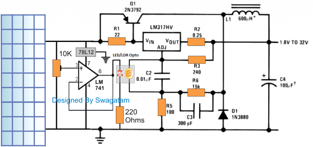
The figure illustrates the discussed MPPT circuit, the LM317 and its associated components form a basic buck converter circuit whose output can be varied by simply varying a resistor across C2.
In our previous power supply design we saw a pot being positioned in parallel with C2 for enabling the variable output voltage feature, however since the present design is supposed to perform an automatic MPPT, this pot could be seen replaced with an LDR/LED opto coupler.
How the Circuits Works
The LED LDR opto coupler is a simple homemade device wherein a red LED and LDR are sealed face to face inside a tiny light proof enclosure.
The LDR leads here can be seen connected in parallel with C2,while the LED is integrated with the output of an opamp voltage follower circuit stage.
The input of the opamp can be seen hooked up with the solar panel through a 10k preset.
The idea here is to make sure that as the solar panel voltage increases, the opto LED intensity also increases, which in turn causes the resistance of the LDR to drop.
The dropping resistance causes the buck PWM is narrow its pulses thereby preventing the output voltage to rise, but nevertheless ensuring a proportionate rise in current for the connected load.
In one of my earlier post we understood that in any buck converter design the output from the converter depends on the PWM and the input voltage.
That implies if the solar voltage tends to increase, the buck output could get affected and begin increasing proportionately. This could in turn cause overloading of the panel and degrade the efficiency of the panel.
The present LM317 MPPT design takes care of this situation through the LED/LDR device and the LM317 variable resistor feature, and combines the two features in conjunction with an opamp voltage follower to develop an effective self adjusting PWM based MPPT circuit.
The adjustment of the opamp 10k preset appears to be quite simple.
How to Adjust the LM317 MPPT Preset
At optimal sunlight, the 10k preset is adjusted such that the output from the buck converter produces a voltage on par with the load voltage specification.
For example suppose the load is a 12v battery, in that case the 10K preset is adjusted to produce around 14.4V.
Once this is done, from here on the output could be assumed to self adjust in response to the sun shine...meaning now as the sun shine increases the LM317 buck converter self adjusts and narrows the PWM at the base of Q1 inhibiting any rise in voltage, but in the process the inductor L1 and C4 makes sure that the excess sunshine is transformed into a proportionate amount of extra current for the battery to enable a faster charging.
Conversely if the sun shine deteriorates, the PWM tends to widen, causing the voltage for the battery to self adjust automatically maintaining the 14,4V level...... albeit with a proportionate amount of reduction in the current.
The self optimizing functionality is carried out throughout the day ensuring the most effective outcome from the panel for the connected load.
WARNING: THE ABOVE EXPLAINED SIMPLE MPPT CIRCUIT USING LM317 IS BASED ON THE AUTHOR'S ASSUMPTION AND SIMULATION, VIEWERS ARE ADVISED TO ASSESS THE CONCEPT THOROUGHLY BEFORE ATTEMPTING IT PRACTICALLY.


Questions & Answers
Thank you sir,
Mppt: this type
image
Solar panel:
I’ve checked the readings for each diodes on my solar panel, none is faulty, the voltage is normal open circuit voltage but I couldn’t check for current because my current meter can not measure that high
Hello Tunji,
Aliexpress does not open in India, so cannot see the image.
You can do one thing, replace your solar panel with a variable DC power supply and feed the variable voltage to the MPPT and check its response.
Though base on my research, all fingers point to my Battery
Yes that might be a possibility also…
Hi sir, and happy new month sir,
I using a 30A PowMr mppt, with a single 24v 300w solar panels and 12v 20Ah battery, sir I wanted to know why my mppt is drawing low current max(1.1A in high sunshine) from my panel, when I did my research I saw many things, but I need your advance knowledge sir, thank you sir
Thank you Tunji,
It is very difficult to say why your specific MPPT is drawing less current, it could simply because your MPPT is malfunctioning, or the solar panel is not providing the max current to the MPPT.
It can be confirmed only after checking the schematic thoroughly.
Hello, I’m very intrigued by this design. Very simple and straightforward. What I would like to know is if it would be possible to use this device to connect to a bank of other solar panels and all their outputs merge into a single line and are fed into an MPPT charge controller. For instance, I have 10 solar panels that were previously used, so their outputs all vary in VoC and ISC, which also effects the Vmp/Imp as well. So I am looking for a way to take all these panels and get the most of each one and then dump that power into a common rail to send back to the MPPT Charge Controller. Would this circuit work for this type of situation? Also would it be easy to add an esp32/8266 for reporting performance of the panels output?
Hi, thanks for your interest in this circuit, however, this circuit is designed based on my assumptions only, and I am not sure if it will really fulfill the mentioned outcome or not.
If you are looking for a simple MPPT concept, I would recommend the second circuit from the following article and I am confident it will provide the intended results:
https://www.homemade-circuits.com/homemade-solar-mppt-circuit-maximum/
You can use the esp32/8266 for reporting performance of the panels output.
How do I design this electronic circuit, and is it possible to have a simple explanation of how it works?
I want to do a bachelor’s thesis on the MPPT device. Can you help me?
Sorry, writing a thesis may not be possible for me, you can take the help of Chat GPT for this.
I have tried to explain the concept in simple words in the above article, but if you are still unsure, you can ask your specific questions, i will try to solve them for you…
I own a charmer plompbde 48v 59.3 V I would like to charge a Lifepo4 150A battery from Huawei. right now I’m charging it, with a 50 volt plonb charger. which of course is not enough, is it possible? without damage?
A 150 Ah Lifepo4 battery might require a 100 amp current to charge rapidly, which may not be possible using an LM317 IC.
Can I use this circuit as a dc motor driver instead of a battery? What is the max wattage that this circuit can deliver without dammaging it?
You can use it for driving a motor also. The output wattage will depend on the current handling capacity of the PNP transistor.
As I see, the buckconverter is exactly the one from the Texas Instruments data sheet for the LM317HV, which I think is good!
I am wondering, if one could spare the operational amplifier LM741 including its voltage regulator 78L12, the LED and the assosiated resistors, if the LDR is just presented to direct sunlight close to the solar panel. Maybe with a potentiometer parallel to the LDR to adjust the output voltage.
That may be possible, but that won’t give you the level of accuracy you can get from the shown op amp/preset setup, nonetheless it is worth trying.
Thanks,
what do you mean by accuracy? Could you please explain, what difficulties you expect?
The op amp preset can be used to create proportional amount potential ranges across the LED/LDR. For example if the solar panel output is between 0V and 24V, this can be adjusted to 0 to 12V or 0 to 5 V proportional voltage ranges by using the op amp preset….this cannot be achieved using the preset across the LDR exposed to direct sunlight.
Thank you for setting this straight.
Would you also have an example for such a MPPT adjustment in combination with a boost converter?
Glad it helped!
sorry, presently I do not have an LM317 based boost converter circuit
Hello, very nice diagram.
I would like to adapt it to charge a 100Ah acid battery. I was thinking of replacing Q1 by an MJ2955 and the LM317 by an LM338 to support more current.
If what I want to do is possible then how do I calculate R2 and L1?
I also plan to add another circuit to manage the battery charging steps, do you have an idea for that please?
Hi, Charging a 100 Ah may be possible, however an MJ2955 might require a very large heatsink. The values of L1 and R2 can be as is, but the wire thickness of L1 will need to be upgraded accordingly, perhaps, a 21 SWG wire for L1 should do the job.
For the battery auto cut off, you can try applying the concepts explained in the following artile:
Op amp Battery Charger Circuit with Auto Cut Off
Hello, since the circuit is based on a LM317 then must Vin be 3V higher than Vout? If this is the case is there a way to set the output to a value.
For example if the panel voltage is 14V, I would like to have an output of 14V. And if the panel voltage is 18V, I would like to have an output of 14V but with extra current.
Hello, the 3 V differential may be true for this circuit also. So at 18V you may get the mentioned results, but at 14V you cannot get 14V, since this is a buck converter circuit, and a 3 V differential may be always required…
Hello,
Since the 3V difference is still needed here, is your MPPT circuit based on an IC555
(second diagram from the end) also requires a voltage drop?
My goal is to design an LDO MPPT circuit to charge 12V batteries (with Vfloat about 14.4V max).
The problem with the LM317 circuit is that it will only be effective in good weather conditions and if the solar panel produces 14+3V or 17V. At 14V as you say, we cannot have 14V anymore.
Hi, I would recommend the following design instead, which will adjust to the input perfectly, and make sure the output is always constant:
https://www.homemade-circuits.com/homemade-solar-mppt-circuit-maximum/
Please Sir can this charge 24v. 12v battery x 2. 200Ah?
No, it is meant for 50 Ah battery maximum
Ok. I love the design. Can it be modified? What do I modify to increase the output to be able to charge it? I am curious because I have already done one but want to ask before trying. The LM741 gets really hot. what if I use LM386?
The IC 741 shouldn’t get hot if the input supply is below 24 V. You can add a 10K resistor in series with the 10k preset and check if that helps. I am not sure whether LM386 can be used as a voltage follower or not.
Lolz. My input voltage is 30v. The 10K resistor in series is a good suggestion. Thanks. What about getting a higher output current. I really want to charge my 12 x 2(24V 200ah batteries). I bought new Epever MPPT but it stuck on the way. No flight coming from China. I thought It will be good idea to use available components in my country to make something I could use for the meantime to save the batteries. Your great knowledge will be helpful. Thanks
No problem, just make sure the 10K is on the positive side of the preset. You can try the shown basic design first, if it works as per the specifications then you can try upgrading it for the 200 Ah battery.
pls i have a 12v, 1200ah battery pack system
i also have 1710 wats solar system at 35v all panels connected in parallel and hopping to increase them soon.
pls could you help me design a real circuit diagram that would help me charge the battery pack most efficiently in mppt mode with the basic functions of buck, constant and float charging stages.
the display on the SOL showing the exact volt and amps from the solar side and the BAT showing the exact volt of the bat and the exact current going into it.
thank you.
NB; i understand the heat dissipation of high current in low volt systems.
Sorry that’s a lot of work, and sounds complex too, not possible for me at this moment.
Hi Swag ,
Thank once more and stay blessed
Dear Swag,
I have made a design of a modified sepic converter which I do intent to use as an led driver for four led corn light bulbs with the following specifications, head voltage of 359 millivolts wattage of 26 watts. The problem I do have is that I am getting power from a battery with the following specs 12 volts 76 amps. I do know the best way to drive led light bulbs is that of constant current. My question is I need a general method of stepping down high current to manageable level to suit the prevailing needs. If it were ac it would have been very easy because I can use either step down transfomer, bridge rectifiers ect.
Dear Bernard, sorry are you sure the forward voltage spec of the LED is 359 milivolta? I have never seen an LED working with such low voltage, please clarify this, I’ll try to figure out the solution…also how do you wish to connect the LEDs, in series or in parallel, I guess it is in series?
Hi Swag ,
I am 100 percent sure that the led light bulb is 359 millivolts.The wattage being 26 watts and its dimmable.I would be glad to give me a general solution as a whole in stepping down dc current to required levels.Thank you.
Hi Bernard, please give me the link of the datasheet of this LED, I’d like to see its specs. If we divide 26 with 0.359V, it gives 72 amps, so do you mean the LED requires 72 amp current to illuminate? Please check the dataseet or provide the link.
please do not put http on the link
Hi Swag
To be quite honest I bought the led lamps from a local supplier
here in Harare Zimbabwe a couple of years and never bothered to
Ask the source that is where they got them from.But its true the lamps corn lights 359 millivolts 26 watts were there its only now that they dont deal with them any more.The shop is called Amanat its a hardware shop.Any way Swag I dont want to give you a tall order.If you can give me a general idea or guide line of how to step down high current to a low one for constant current
Led drivers .I would be glad .I can forget about this one and start
On something new. Sorry for giving so much head ache on this one.
Hi Swag,
Thank you very much for your untiring support. Truely you are a rare person to find and may god bless you in all you work.
No Problem Bernard, I am always happy to help!
Hi Bernard, To drive an LED from a higher DC to a lower DC, you can use linear ICs like 7812, 7805, LM338…for current control you can apply the following concepts:
https://www.homemade-circuits.com/universal-high-watt-led-current-limiter/
https://www.homemade-circuits.com/simple-current-sensor-circuit-modules/
https://www.homemade-circuits.com/make-hundred-watt-led-floodlight/
https://www.homemade-circuits.com/constant-current-source/