In this article I have explained a 32V, 3 amp SMPS circuit which may be specifically used as an SMPS 100 watt LED driver, rated with the same specs.
The circuit of the proposed 32 V, 3 amp smps led driver may be understood with the the help of the following points:
Circuit Operation
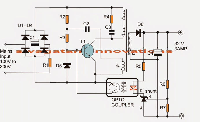
The mains voltage is rectified and filtered by the bridge network and the associated filter capacitor C1. This rectified 310 V DC passes through R1, R2 and triggers T1 into conduction.
T1 switches ON and pulls this DC to ground through the 30 + 30 primary winding inducing a steep pulse through this winding and also across the lower auxiliary winding.
This pulse across the auxiliary winding enables a negative pulse to be generated at the junction of R1/R2 which momentarily sinks the base drive to ground such that T1 now shuts off.
In the meantime C2 charges up drying up the auxiliary winding impact, and allows T1 with a fresh triggering potential at its base.
T1 conducts yet again and the cycle keeps repeating at a frequency determined by the value of R2/R3/C2 which could be around 60 kHz here.
This rapid switching induces a corresponding voltage and current across the secondary winding which may be well over 32 V, 3amps AC as per the given winding details.
The above voltage is appropriately filtered by C4 and applied across R6, R7 for feeding the shunt regulator and the opto coupler stage.
R6 is appropriately adjusted such that the output voltage settles to about 32 V.
The Shunt Regulator
The shunt regulator instantly activates the opto in case the voltage tends to rise above the set value.
The opto in turn "kills" the base drive of T1 temporarily disabling the primary operations until the output potential is restored to the correct value, the opto now releases T1 and allows the operations to work normally, only until the output rises again to initiate the opto yet again, the process keeps repeating ensuring a constant 32 V at the output, for driving the 100 watt LED module safely
Circuit Diagram of 32V 3A LED Driver for 100 Watt LED
The transformer is wound over a standard EE ferrite core having a central cross sectional area of at least 7 square mm.
Referring to the figure, the upper two primary winding are made up 30 turns of 0.3 mm diameter super enameled copper wire.
How to Wind the Ferrite Transformer
The lower primary auxiliary primary winding consists of 4 turns of the same wire as above.
The secondary is wound with 22 turns of 0.6mm super enameled copper wire.
The procedures are as follows:
- First begin winding the upper 30 turns, secure its ends on the bobbin leads by soldering, and put a thick layer of insulation tape over these turns.
- Next, wind the secondary 22 turns and solder its end terminals on the other side of the bobbin leads, put a layer of thick insulation tape.
- Over the above layer start winding the auxiliary 4 turns and as above secure the ends appropriately on the primary side leads of the bobbin, again put some layers of insulation over this,
- Finally, wind the second 30 primary turns starting from the previous 30 turn end, and secure the end over one of the leads of the bobbin on the primary side.
- Cover the finished winding with additional layers of insulation tapes.
- Make sure you remember the terminated leads properly so that you don't make incorrect connections with the circuit and cause a possible fire hazard.
Parts List
All 1 watt, CFR
- R1 = 10E
- R2 = 1M
- R3 = 470E
- R4 = 100E
All 1/4 watt MFR 5%
- R5 = 470E
- R6 = preset 22k
- R7 = 2k2
- C1 = 10uF/400V
- C2 = 2.2nF/250V
- C3 = 220pF/1kV
- C4 = 2200uF/50V
- D1---D4 = 1N4007
- D5, D6 = BA159
- shunt regulator = TL431
- opto = 4n35
- T1 = MJE13005
Useful Feedback from Mr. Kanicaras about the above circuit
Well, I tried experimenting with transformer, and doing so, I found quite a few things about the circuit:
First of all (unfortunately), this circuit is inappropriate as power source for the power supply, because the transistor blows, when circuit is not loaded (or is loaded too little).
It works well only with the load (such as 100W LED) connected to it all the time. Learned it the hard way – blew three transistors. I think that TL 431 is the culprit here. It is rated only 37V Cathode to Anode voltage.
When circuit is unloaded, it struggles to regulate the voltage at 32V (very near its own brake down voltage) and after 30 seconds or so it stops regulating (maybe because of the sporadical pulse larger than 37V) and the voltage goes up through the roof, taking down the transistor (I think through the feedback coil, because of the sharp voltage increase in it).
Secondly, I think that there are too many turns in secondary coil. 22 turns can give more than 70V unloaded (saw this number after loss of regulation, just before transistors blew) I think, that 15 or even 10 turns would be enough for 32V at the output (winding 2 or more wires in parallel).
By the way, increasing C2 capacitor value to 10 nF or more, decreases the frequency of the oscillation to human audible range (~14 kHz, checked on oscilloscope and also faintly herd it). So, I guess, its not such a good thing after all ;).
The ferrite core, that I got, came from a very old ATX so I'm not sure that it is "standard"
I found another bigger transformer. I'm going to disassemble it and try to use it in this power supply
I'll certainly try parallel strand "tactics".
Besides that, I'm going to buy some parts (including 220 pF capacitor and 4n35 opto), because, interestingly, I "fried" R5 resistor by accidently shorting the output of the power supply (while trying to connect the small light bulb :).
The lead welded itself to the light bulb and in 1 or 2 seconds (that's how long it took to disconnect it) R5 went up in smoke.
I guess that's one of the disadvantages of this power supply – you cannot short it under any circumstances. I imagine what it would be like if it was not 4 W (in my case) but fully functional power supply at 100 W.
Before I "fried" R5 resistor I tried this power supply with 120V AC input (I have DIY 100W 220V/220v/110V isolation transformer) and it gave less voltage and power than with 220V. Is that normal (is this power supply calculated only for 220V mains)?
Potential Improvements
I didn't give up on this circuit, and it paid off I replaced the shunt regulator – the circuit worked a little bit better (gave a bit more power).
But the most important change occurred, when I decided to change C2 capacitor (its value in my prototype circuit was a bit off ~1.99 nF).
When I put 2.2 nF capacitor in, the power output grew a bit more. Then I decided to increase it again and when I reached 10 nF the output was reaching ~40W (20V at ~2A and that's with my very first small transformer).
The second thing that happened (after I increased C2 value) was, that transistor started heating up quite rapidly (in my prototype board I didn't attach the heat sink to it yet, I just switch it on for a short periods of time).
I think, that this shows, that there is something wrong with the parameters of the transformer itself (maybe, that's why adapting the circuit to the transformer helped?)
I don't really know, if it's the right way to go though.


Questions & Answers
čitam vaše razgovore svaka čast g.svagatam na dobrim živcima.diskutirati sa ljudima koji jako malo znaju o elektronici i struji je teško.samo jedan primjer,ljudi misle da su pojam struja i napon odvojivi.jedno bez drugog ne postoji.samo tolko,hvala
Thank you very much for your kind words. Yes you are right…discussing electronics with beginners can be challenging. Many people think voltage and current are separate but actually one cannot work without the other. Voltage creates the push and current flows when the circuit is complete. Thanks again for your comment.
Dear Mr. Swagatam, I didn’t say the circuit didn’t work. It was due to my inadequacy. I’m 66 years old, and I’ve been working with the parts I had at my disposal to the best of my ability. I appreciate and respect everything you say. I’ll work on this anyway. I came up with this idea because I didn’t want to bother you any further. Thank you very much for your interest. I’d also like to point out something. I used MUR460 instead of BA159s. Would that be a problem? Good work.
No problem at all Dear Akman, I understand and appreciate your kind thoughts and feedback.
You can ask me as many questions as you want, I am always happy to answer them.
Yes, MUR460 is perfectly fine, and should work without any problems.
All the best to you, and let me know if you have any further problems with the circuit…
Dear Mr. Swagatam, I rewound the transformer according to all the instructions. It’s perfect, exactly as described. The transformer core diameter is 11mm. It’s an EERound transformer. I rewound it with new wires every time I rewound it. I also left the paper gap, but now it’s worse than before because it shorts out. While the series lamp is on at the 220V input, the transformer’s AC input is 9v. I can’t get a bias measurement. There’s only a Mur460 rectifier diode at the output, and there’s no reading. The secondary was wound with 50 turns of 0.30×2 wire. The gap is 1.10mm. I don’t think I’ll be able to get this circuit to work. Thank you very much for your efforts. Can you recommend another 32V 2-3A circuit that works 100%? Keep up the good work.
Thank you Akman, for your efforts to build this circuit… and I am sorry you could not succeed with this project, however if you read the older comments you will find that a few readers were able to complete this project successfully, although with limited results, the readers who practically tried this circuit successfully are A.M. Choudhary, s3nsit, kanicaras. You can find them in the second comments page.
I have updated the above article with the feedbacks from Mr. Kanicaras, at the end of the article, you can check it out….
I think this circuit will work only if the transformer correctly resonates and oscillates with the transistor, so the transformer winding is the critical part here, which needs extreme care for it to work correctly.
If you want a more reliable design which does not depend on feedback oscillation concept, you can try an IC based design, as given in the following article:
https://www.homemade-circuits.com/smps-halogen-lamp-transformer-cicuit/
Hi Mr. Swagatam.
I disabled the feedback section as you suggested. The serial tube showed a short circuit, and a buzzing noise started coming from the transformer. I kept the gap open at every attempt, trying values like 0.5-0.7-1-1.5mm. It’s currently at 1mm. The transistor is a 13007 and is fine. I’m considering rewinding the transformer. Thanks for your interest.
No Problem Akmal, please try it and let me know.
Please wind the transformer exactly as explained in the article. For air gap, please use a paper insertion between the E core legs…
Dear Mr. Swagatam, I measure 7.54V input from the transformer’s primary input. The secondary output is 4.11V. After the filter, it’s 4.60V. The transformer has 4.80V at the auxiliary winding input. The TL431 has a reference voltage of 4.62V. I connected a multi-turn 20K trimpot instead of R6, but it doesn’t respond at all. Thank you.
Dear Akman,
Can you please remove the whole feedback opto-coupler network completely from the circuit, and then check the DC output?
I am assuming you have done everything as given and explained in the above article.
Please check it and let me know….if still the output voltage is low try increasing the 22 turns to 50 turns and check the results.
And I hope you have added an air gap between the cores, as described in the following article:
https://www.homemade-circuits.com/how-to-create-air-gap-in-a-ferrite-core-transformer/
Hello Mr. Swagatam.
I have installed the circuit above many times. I have strictly complied with the points you have made. I rewound it 3 times in case I couldn’t wrap the transformer. There is no problem in the 310V section of the circuit. But I cannot get voltage from the shunt regulator TL431. I used Pc817 instead of 4n35. I also tried 13007-13009 instead of 13005, but I could not get voltage from the auxiliary winding and sconder outputs in any way. I need your help on this.
Hi, Akman,
Did you do the strictly follow the orientation of the winding, as per the given black dots on the winding? The black dots on the winding denote the start of the winding, and if this is not done correctly then the circuit will fail to oscillate…Please let me know if you have further doubts..
Hello, Mr. Swagatam.
I didn’t know these points were the starting points. I think I did a reverse winding. I’ll rewind as you suggested, test it, and let you know the results. Thank you for your interest. This is the first time I haven’t been able to get a circuit you’ve designed to work. Thank you very much. I wish you success in your endeavors.
No problem Akman, I understand!…please do it and let me know.
Actually the above circuit was not designed by me, it was contributed by another author, and he claims that he has tested the circuit successfully…
many thanks for your best wishes..
sir, do you have any youtube account about your project?? if you have, please share the link of your channel.
Hello Shamim, I do not have a youtube video for the above concept.
What must be modified,if you want a voltage output of 50 volt and a current of 6 Ampere.
Tank you.
For the voltage adjustment, first disconnect the collector of the opto-coupler transistor from the base of the T1, and check the output voltage. If it is above 50V then no need to change anything in the secondary winding. Now reconnect the collector of the opto transistor with the base of T1 and adjust the values of the R6 and R7 until you get a fixed 50V.
If it is less than 50V, then you have to increase the secondary winding and repeat the above procedures.
For increasing current, you may have to increase the wire thickness of both the sides windings.
at the output 3 amp how can we use BA159 its 1amp diode
Yes that’s right, please change it to a 5 amp schottky diode.
sir you have not defined the primary inductance of transformer
Hello Sanjay,
Inductance value is not known to me, and I think it is not required since the winding specifications are given in details.
Hello swagatam pls help me .I built this smps circuit but it doesn’t work am not getting any voltage at the output of the transformer and secondly I used 13003 transistor instead of 13005 due to unavailability but it didn’t work so I now changed the 13003 to 13001 transistor which it blew up again i don’t no why but pls help me asap……..
Hello Okongwu,
the person who contributed me this article has tested this design successfully.
However, please remember that the heart of any SMPS is its transformer. If you make even a smallest of mistakes in the transformer winding then it may have serious consequences or it may simply not work.
I would suggest that initially you keep the opto feedback cut off or removed from the circuit and test just the basic response.
Make sure to provide a paper gap between the E core legs where the two e cores join with each other.
Always use a 40 or 60 watt bulb in series with the 220V mains while testing an smps circuit.
Dear swagatam I used an EE16 FERRITE core transformer with no air gap ,and what is the importance of an air gap in a FERRITE transformer. And pls can I have your WhatsApp number I wish to learn more from you
Thank you…….
Hi Miracle,
Air gap or paper gap prevent the transformer core from getting saturated which can otherwise result in short circuiting of the switching transistor.
You can communicate with me through this blog comment platform since I am mostly online with my blog. You can ask as many questions as you want, I will try to help.
Hello swagatam how can I reduce the voltage of this circuit to 4.2v in order for me to charge a lithuim ion battery???
Hello Okongwu,
For 4.2V you can try the concept explained in the following article:
https://www.homemade-circuits.com/220v-smps-cell-phone-charger-circuit/
Swagatam, good afternoon.
I am an industrial automation engineer.
I am doing such a project, it is for people with low incomes.
https://www.facebook.com/dan.saudabaev/posts/pfbid02nT1yLhhQ4kspxVPupVZtntpHeiCMfnLPmBa5KoxWeu2QJ6gn8Gmk7bqbDXFtiFkjl
I bought samples of lamps on Sanan & Seuol diodes, spectrum 5000k+660nm (for leafy greens) – lamps 24V/40W (1.66A).
We sell regular switching power supplies
POWER SUPPLY 24V 20A 480W ($16).
There is no 36V.
I want to connect DC-DC converters (XL4016) to it.
It has two resistors for voltage and current.
– stabilization in both current and voltage (right?)!!!
Set the output to 24V, reduce the current for the lamps by 5% (1.58A).
And connect the lamps in parallel.
Sir, reducing the current by 5% will give me a guarantee that all the lamps will work without any problem?
In the description –
10. For example: input 12V * 5A = 60W, input 24V * 5A = 120W
Input 36V * 5A = 180W, input 48V * 5A = 240W
Sir, approximately how many watts can this DC-DC converter produce?
Efficiency, if 4-5A will be higher than 90%?
Another option is a DC-DC converter:
I asked them questions in the morning, they promised to answer, but there is still no answer. There are few specialists there… – they can’t even answer basic questions!
Thank you Dan,
If the current limiting is set to provide 1.58A then the LED lamps cannot get more than this value. So if the requirement for your parallel LED lamps is more than 1.58A then their light intensity will become reduced and they will look dim.
Swagatam, hi.
You’re right –
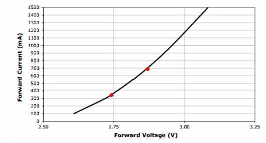
You can see this clearly from the electrical characteristics of the Cree XP-G2 below in Figure 1. When the LED is turned on, even the smallest 5% change in voltage (2.74V to 2.87V) can create a 100% increase in current driven to the XP-G2 as you can see at the red marks current went from 350mA to 700mA.
– I’m very surprised that a minor change can have such an impact!!!
Thank you)))
Thanks Dan,
Yes i agree.
As the voltage nears the LED’s maximum forward drop level, the current tends to increase drasitically. That is why it is crucial to have a constant voltage supply which can never exceed the forward drop level of the LED.
Sir, excuse me, one more question.
Where I ordered samples of lamps, a girl works there as an engineer.
They agree to check the connection of 8 lamps to this driver.
But she claims that they have constant voltage lamps (24VDC, 40W) and this driver will not work.
I explained to her that there is no such thing as constant voltage or constant current lamps.
I asked for a wiring diagram for the diodes, but for the second day it was silent.
I gave them a diagram of how to check –
https://photos.google.com/photo/AF1QipNMR479Lv7Msybv3Nj5RwHU9G9kY520JSYeVax5
Using Variac Auto Transformer we change the input alternating voltage 150-250V, using multimeter 2 we look at the variable voltage, using multimeter 1 we look at the fixed current (1.66A).
I don’t know how else to explain to them))))
Maybe you can help?
Dan, You can show me the picture link of the lamp, I will try to figure out its specifications.
The link of your google photos is not opening in my computer.
Sir, sorry, I’ve been working all day.
I made the link wrong.
https://photos.app.goo.gl/ChLTCjH344kk6yzM8
Hi Dan, THe voltmeter and the ammmeter connections are correcty wired. No problems.
Good morning sir.
https://photos.app.goo.gl/KsTvj643rAYi2K1s9
– this is the programmer they have.
That link is not working.
Sorry, I did not understand what you mean by programmer? I actually asked about the LED specification which you are having problem with.
Programmer – I’m talking about the capabilities of this company that produces drivers.
https://drive.google.com/file/d/1s5KFJelMUinbIDeyOztnIIc3_tKuxfMO/view?usp=drive_link – just received.
– diode connection diagram.
They made me two samples using diodes:
– SANAN MH-S3030E23C50HE
– SEOUL 3030C.
They claim that voltage drivers are needed for these lamps.
Are there diode circuits for voltage or current?
Your first googlr dive link needs to be in the shared mode otherwise it won’t open for me.
You can see in the second link, all the specifications of the LEDs are given.
You simply need a constant voltage and a constant current LED circuit adjusted to the above specifications, that’s all, and the LED will be safely driven. Ofcourse if the LED heat up a bit then you might require a heatsink also.
Good afternoon sir.
Sorry, I’ll repeat it again.
The company that produces the lamps claims that their lamps are for voltage drivers.
I sent you their lamp wiring diagram, there are 276 diodes.
They have 10 sections (each with 27 diodes), I think there is such a connection – https://drive.google.com/file/d/1N1w1mSncy970dPmukWq9ivNcBqu1UG08/view
Swagatam, these lamps, if you connect them 8 in series – https://photos.app.goo.gl/ChLTCjH344kk6yzM8
– will they work under a current driver?
I have no doubt that these lamps will work under both a current driver and a voltage driver – there is no difference there!!
Hi Dan, Your Google drive link is not opening because you have not sent it in shared mode.
Yes, LEDs in series will work with constant current driver circuit.
Using a constant voltage and a constant current driver is the best option.
https://photos.app.goo.gl/WXpbqmcuN3fisnFt7
– opens?
They have 276 diodes on the lamp.
I took one sector (there are 10 in total).
There are 27 diodes in this sector.
If we take an operating current of 65 mA, then the result is a current of 195 mA in three parallel circuits.
If there are 10 sectors, then the total is 1.95A.
However, they state that the lamp is 24V and 1.66A.
Are they wrong or am I wrong?
Yes the image opens now.
Your calculations are perfectly correct.
Did you ask them the reason why they state it should be 1.66 amps?
It maybe because they want to reduce stress on the LEDs to enhance their life.
By the way if 65 mA is the maximum breakdown current of these LEDs then it may be recommended to use a current that’s below 65 mA
Thank you sir ))))
As an LED lighting specialist, you helped me a lot!!!
You are most welcome Dan, Glad I could help!
– constant voltage driver?
Sorry to interrupt you…
But if the external voltage jumps, and the driver output has a stabilized voltage
– then the current will change, which will have a very negative impact on the diodes!!!
I chose the fixed current driver DL-400W-V260X-PLS
Input voltage 120-277V.
They told me that they could use a programmer to fix the current I needed (1.66A).
And I want to connect 8 lamps in series (24VDC, 40W, 1.66A).
– Am I doing it wrong!???
Dan,
With a consant voltage regulator the voltage to the LED can never jump, unless the input AC becomes exceedingly high, which would anyway destroy all forms of stabiliziing elements.
If the DC voltage is fixed or constant then current becomes immaterial, meaning larger current will have no impact on the LED. For example if you supply a 3.3 V to a 3.3 V LED, with a current of a million amps, the LED would still illumnate safely and draw only the amount of current it needs optimally at 3.3V.
Conversely, if you have a fixed or a constant current then the voltage becomes immaterial, meaning suppose if you have a current limit applied to a 3.3V LED, then even if the volatge increases to 100V or 1000V it would drop down to 3.3V without harming the LED.
If you are too much concerned then you can have both constant current and constant voltage supply for your LEDs.
Hi, have you got PCB project for this power supply?
Hi, sorry, a PCB is not available for this project!