In this article I have explained about a simple non-contact current sensor circuit using a hall effect sensor IC.
Why Hall Effect Sensor
When it comes to sensing current (Amps) linear Hall-effect devices are the best and the most accurate.
These devices can sense and measure current right from a few amps to many thousands.
Moreover it allows the measurements to be done externally without necessitating a physical contact with the conductor.
When current passes through a conductor, typically a free-space magnetic field of around 6.9 gauss per ampere is generated.
This implies, in order to get a valid output from the Hall-effect device it needs to be configured within the range of the above field.
For conductors with low currents this means the device needs to be configured inside specially designed arrangements for enhancing the range and the sensing capabilities of the sensor.
However for conductor carrying high magnitudes of current, any special arrangement may not be required and the linear Hall-effect device would be capable of sensing and measuring the amps directly by positioning itself within a gapped torroid.
Calculating Magnetic Flux
The magnetic flux density over the device may be formulated as under:
B = I/4(pi)r, or I = 4(pi)rB
where,
B = field strength in Gauss
I = current in Amperes
r = distance from the center of the conductor to the positioned device in inches.
It may be noted that a Hall-effect element will produce the most optimal response when it's positioned perpendicular to a magnetic field.
The reason being, reduced generation of cosine of the angle compared to angled fields at 90 degrees.
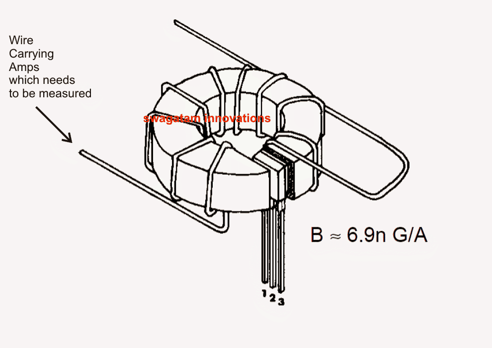
Non-contact measurement of current (low) Using a Coil and a Hall-effect device
As discussed above, when lower currents are involved measuring it through a coil becomes useful since the coil helps to concentrate the flux density and hence the sensitivity.
Enforcing Device-to-Coil Gap
By enforcing a device-to-coil air gap of 0.060" the effective magnetic flux density achieved becomes:
B = 6.9nI or n = B/6.9I
where n = number of turns of coil.
As an example, for visualizing 400 gauss at 12 amperes, the above formula may be used as:
n = 400/83 = 5 turns
A conductor carrying lower magnitudes of current, typically below 1 gauss become difficult to sense due to the presence of inherent interference normally accompanied with solid-state devices and linear amplifier circuits.
The wide-band noise emitted at the output of the device being typically 400uV RMS, resulting an error of about 32mA, that could be significantly large.
In order to identify and measure low currents correctly, an arrangement shown below is utilized wherein the conductor is wrapped around a toroidal core a few number of times (n), giving the following equation:
B = 6.9nI
where n is the number of turns
The method allows low current magnetic fields to be enhanced sufficiently for providing the Hall-effect device an error free data for the subsequent conversion in volts.
Non-contact measurement of current (high) Using a Toroid and a Hall-effect device
In cases where the current through the conductor may be high (around 100 amps), a Hall-effect device may be directly used via a spit-section toroid for measuring the magnitudes in question.
As can be seen the figure below, the Hall-effect is placed between the split or the gap of the toroid while the conductor carrying the current passes through the torroid ring.
The magnetic field generated around the conductor is concentrated within the torroid and is detected by the Hall device for the required conversions at the output.
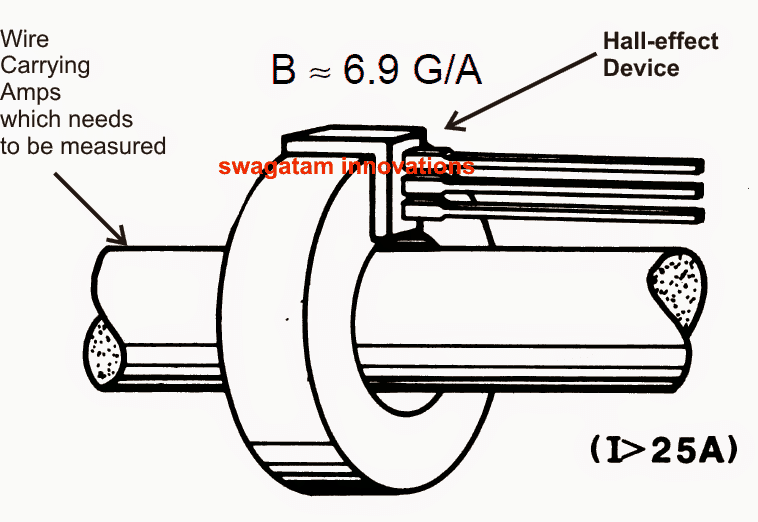
The equivalent conversions made by the Hall-effect can be directly read by appropriately connecting its leads to a digital multimeter set at mV DC range.
The supply lead of the Hall-effect IC should be connected to a DC source as per its specifications.
Courtesy:
allegromicro.com/~/media/Files/Technical-Documents/an27702-Linear-Hall-Effect-Sensor-ICs.ashx


Questions & Answers
Hello,
I have been given so much run around and no real answer to this inquiry of mine. A real circuit so I can build this simple set up.
I like to connect a hall sensor to a power mosfet. The mosfet is to feed a coil of wire with a diode across it to stop back emf.
All I want is that when a magnet passes across the hall sensor the mosfet energizes the coil and when the magnet is not in the vicinity of the hall and has passed it, I like the coil de-energized, the power off to it, i.e. mosfet Off, no current is passing through it.
[The way these hall sensors are, they operate backwards. Output does not mean positive ( which is instinctual to think). When they say output they mean as in negative, the same voltage as the ground part of the circuit, basically the definition of output means ground state, while when there is no magnet, its output is truly output, i.e. positive high.
And there is of course no point in time where the output pin is 0, zero. In other words not part of the circuit, as in dead wire].
I thank you in advance for a real circuit I can look at. Only because I feel it may not be too involved. If it is too much to ask, then I understand.
Only because I have been given plenty instruction word wise, Enough words to fill a book that to turn it into a diagram would have taken a fraction of the time that the words I have been treated with.
Please accept my apologies as I do not mean to come across imposing to get a diagram. No worries if not possible.
Hello, you cannot use a Hall effect sensor directly with a MOSFET, due to a low voltage output from the sensor.
You will have to add BJT stage or an opamp stage and then connect the MOSFET to these stages.
You can refer to the following post for more info:
https://www.homemade-circuits.com/linear-hall-effect-sensors-explained/
Thank you for getting back with me. I might have made a mistake, Just to make a quick correction there is only 2 wires going into the probe not 3. I would send a complete diagram if I had a way.
so, 2 wires are providing the voltage to put power into the board if what is under test is not powered, this voltage is variable from 25 mVDC to 550 mVDC. these 2 wires are separate from the non contact probe. one can power up the board under test and not use the provided voltage mentioned.
what goes into the probe is 1 ground and the other line has no power at all. when measure both from ground to the other wire, I got from about 10 mVDC to 30 mVDC fluctuating up and down.
thank you again for taking the time to replay.
bob
No problem, I am happy to help!
In that case, possibly the sensor is a small inductor, which is absorbing the alternating magnetic field from the wire and converting it into a small potential difference, which you are able to measure as 10 mV
Or it could be a magneto-resistor, which has a property of changing its resistance in response to magnetic field.
However, since you are measuring the generation of voltage across the probe, then most probably it is a small sensitive inductor
Hi there thank you again for your reply,
the 10 mv I am measuring is not off of the probe. I don’t have a probe.
the 10 mv I am measering is from the 2 pins that the probe would connect to on the machine.
wow, magneto-resistor, the first time I hear of that. thank you.
I think it’s either a magneto-resistor or a inductor as you mentioned.
the only measurement I have off of the probe is from someone who has a mchine like this. and he gave me the below infor:
he measured 10 ohms and 220 uH between the 2 pins of the probe.
best
bob b
OK got it, so the 10 ohm 220 uH data also clearly points towards an inductor inside the probe, and anyway only an inductor has the capability to transform magnetic field into current passively. Hope it is genuinely true and solves your query!
Guess what I wound some very thin transformer wire around a piece of plastic and soldered the end to wires connected to the machine and I’m definitely got response from it on a known shorted test board. Conductor it is sir. Thank you very much.
Sounds great! thanks for the feedback!
thank you for this article. currently I am stuck on making a non contact current probe for an electronic diagnostics instrument called Polar Toneohm 950. I will try to explain below what I am working with. and let me 1st apologize for the long comment. but I was wondering if you would kindly give me any input guiding me on the path to make this probe.
This is a short locating unit that uses sound to guide the use to short location on a PCB.
I got the unit for a good deal but less probes. Later found out the 3 sets of Probes cost over $700, Ouchhhh!!#j((0.
so, I decided to try making the probes my self. they are called the Needle, Trace-Drive Source & Plane Probes.
The Needle Probe is already made and it seems to be working OK.
The Plane probe, this one is 1/2 way made.
The Trace & Drive Source Probe (this is the non contact). I am stuck on this one. it has 3 pieces.
2 clips and 1 non contact probe. The clips supply the variable drive source voltage (DS) of around 20 mvdc to 550 mvdc. and the non contact Probe which has 2 wires go into it, is used to trace the current being spent.
One choice is to inject drive source (DS) voltage in the board. The 2nd choice is to power the board with its own power supply. Then with either choice, the non contact probe is used to locate the fault.
I was wondering, given the non contact probe has only 2 leads going to it and 1 of the leads is to the ground. could this give any indication to an adjudicated person in the field, what this probe is made of.
other info that I have on the non contact probe: the 2 leads that go in the non contact probe has resistance of 10 ohms and 220 uH. this was given to me by someone who has a unit with probe.
Glad the article helped you! The last concept seems to be the one matching your probe specifications. So referring to the last concept we can see that the only active sensing element used in the probe is the Hall effect sensor, which has 3 pins. Two pins are used for supplying the biasing voltage to the device while the 3rd one is used for extracting the magnetic information from the core material, which is equivalent to the magnitude of the current passing through the central wire!
So basically the 3 wires that you are referring to could be
+3V
Ground
Ouput