In this post I have explained a 48V solar battery charger circuit with high, low cut-off feature. The thresholds are adjustable through individual presets. The idea was requested by Mr. Deepak.
Technical Specifications
Hi Swagatam,
Thank you for UPS relay circuit.
I am trying to build it very soon. I will update you the result once i am done with that.
Next, i am very keen to build a Solar charge controller circuit for following requirement.
1. Battery shall be of 48 V (lead acid or maintenance free) with capacity go up to 48V X 600 AH.
2. Load to battery may be up to 1500 W (30 Amp at 48V)
3. Solar PV cell in series/parallel configuration producing voltage up to 60V and 40 Amps
The controller circuit is expected to perform as follows.
1. Cut off solar supply to battery when its voltage reaches approx 56V and maintain appropriate hysteresis to avoid frequent switching of power MOSFET. So the solar supply to battery would resume again only when the battery voltage reaches approx 48 V.
2. Low voltage disconnect of load from batter supply when battery reaches around 45 V and maintain appropriate hysteresis to avoid frequent power ON/OFF of load.
I will be grateful if you could help me building this circuit.
Thanking you.
Best regards,
Deepak
Circuit Operation
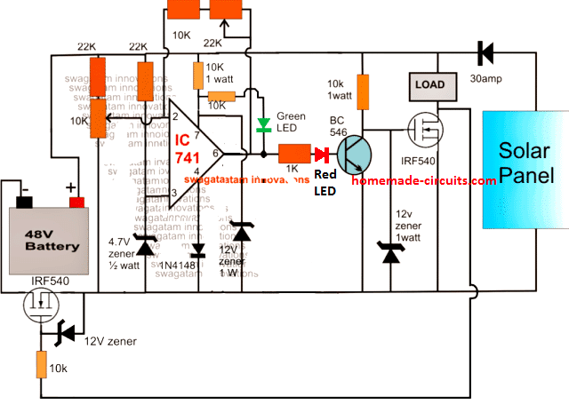
The proposed 48V solar battery charger circuit with high/low cut off feature can be witnessed in the following diagram.
The functioning of the circuit may be understood with the following points:
The IC 741 is configured as a comparator and is appropriately stabilized from the high 48V input using zener diodes and potential divider networks across its supply and input pins.
As requested, the input voltage which may be in excess of 50v is acquired from a solar panel and applied to the circuit.
The 10k preset is adjusted such that the power mosfet cuts off when the connected battery reaches the full charge level.
The 22k preset is the hysteresis control for the circuit and also serves as the lower threshold adjustment preset.
It should adjusted such the the MOSFET just initiates and switches ON at the preferred low battery voltage threshold.
Once the discussed set up is implemented and power switched ON, the discharge level of the battery drags the supply to around 48V forcing pin2 of the IC to go below pin3 potential.
This prompts the IC output pin6 to go high initiating the MOSFET connected in series with the ground rail so that the battery becomes integrated with the solar panel supply.
The above also switches ON the BJT BC546 which in turn makes sure that the associated MOSFET and the load remains switched OFF.
As soon as the battery attains the full charge level, pin2 is pulled higher than pin3 rendering the output to a logic low.
This instantly switches OFF the ground rail MOSFET and the BJT enforcing two things: cutting off supply to the battery and switching ON the load MOSFET such that the load now gets access to the supply voltages from the panel as well as the battery.
The feedback hysteresis network formed by the 22k preset and the series 10k resistors ensures that the above action locks ON until the battery voltage reaches below the predetermined lower threshold.
Circuit Diagram
Diagram
Feedback from Mr. Deepak
Hi Swagatam,
Thanks for Solar charge controller circuit.
The circuit appears to be little different than what i had requested. Let me reiterate the requirement again.
1. Solar panel should continue charging battery not beyond 56 V.
2. In the event of battery discharge, the charging process should resume again only when it reaches 48V. In other words hysteresis should be maintained.
3. Battery should continue supplying power to load when battery voltage remains in between 42 - 56V.
When battery voltage reaches 42V (due to battery discharge) the load should be disconnected from battery supply.
Once the load is disconnected, it should remain disconnected till the battery voltage reaches minimum 48 V during charging process.
Please confirm if the circuit works as above.
Implementing Window Comparator
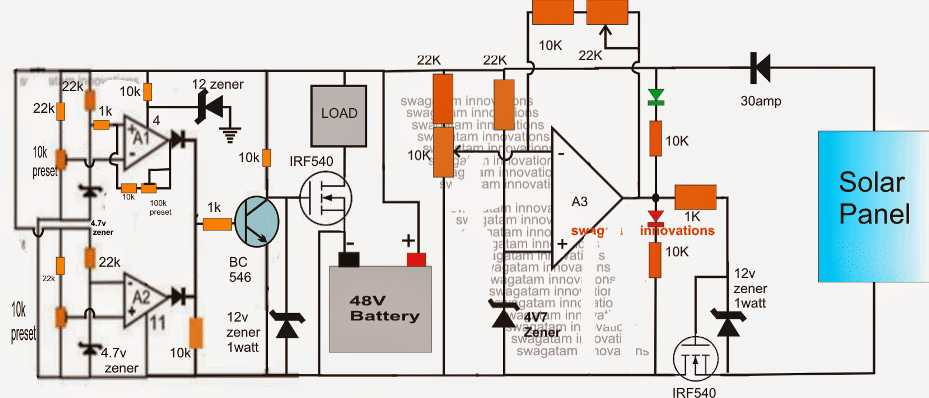
The above 48V solar battery charger circuit with high, low cut-off may be modified with these specifications by introducing a window comparator stage, as shown at the extreme left of the circuit below.
Here the opamps are replaced by three op amps from the IC LM324.
The window comparator is made by two of the 4 opamps inside the LM324.
A1 preset is set such that its output becomes high at the lower threshold level of 42V.
The 100k preset is for adjusting the hysteresis level so that the situation gets latched until 48V is reached.
Similarly A2 preset is set to make the relevant output go high at the higher threshold of 56V.
At voltages between these "windows", the BC546 remains shut off allowing the associated mosfet to conduct and feed the load with the required supply from the battery.
Once the thresholds are crossed, the BC546 is forced to conduct by the relevant opamp shutting down the mosfet and the load.
The A3 stage could also be replaced with an identical window comparator as discussed above for controlling the charging of the battery by setting up the presets appropriately, this would allow using all the four opamps from the IC LM324 and also make the operations much accurate and sophisticated.
Adding a Buzzer Indicator Stage
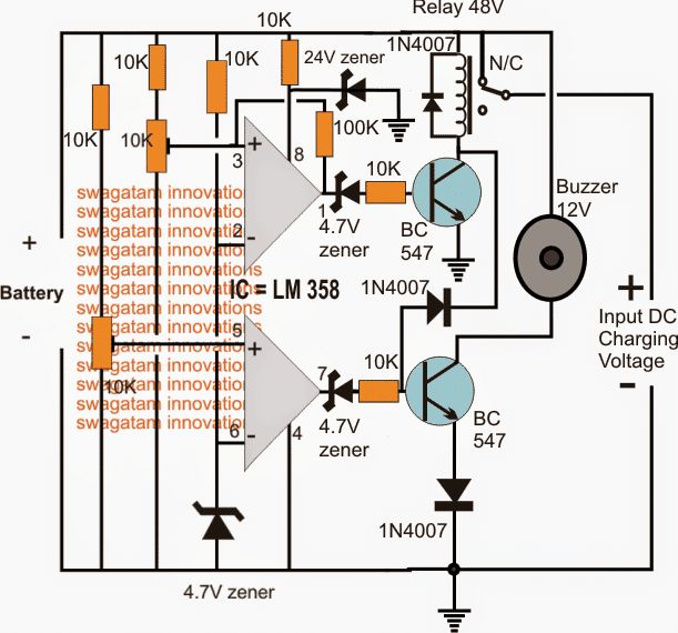
Another version of a 48V automatic battery charger cricuit using a buzzer indicator can be studied below:
The idea was requested by Nadia, please refer to the discussion between Nadia and me in the comment section for more info regarding the design
The transistor are incorrectly shown as BC547, which must be replaced with BC546 for preventing circuit malfunction and damage
How to Set up the above 48V Battery charger circuit with buzzer
Do not connect the charging voltage from the right side.
Keep the 10k preset slider arm towards ground initially.
Connect a DC input using a DC variable power supply from the Battery side on the LEFT of the circuit.
Adjust this voltage to the required potential at which the buzzer needs to get activated....as per the request it should be at around 46V
Now adjust the lower 10k preset very slowly and carefully until the buzzer just activates and starts buzzing.
Seal this preset with glue.
Now increase the input voltage to the desired high cut off level.... which is 48V as per the request here.
Next, adjust the upper 10k preset very slowly and carefully until the relay just clicks. When this happens the buzzer should shut off.
The 48V solar battery charger circuit with high, low cut-off is now set, however the value of the 100k resistor which can be seen connected between the input/output pins of the upper opamp actually decides at what lower threshold the relay must deactivate again, and switch ON the buzzer.
It's been arbitrarily fixed, you may have to adjust the 100k value so that the relay toggles only at around 46V...it may be confirmed with some trial and error
48V automatic solar battery charger using relay
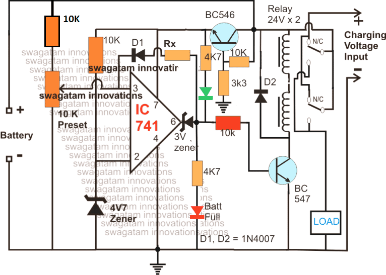
The operations involved with the first diagram above gets much simplified if a relay stage used instead of BJTs, and mosfets.
As can be seen in the above updated diagram, the relay stage is in the form of two 24V relays in series, wherein the coils are joined in series while the contacts are joined in parallel.
The sensing circuit is applied with a proportionately scaled down voltage through an emitter follower voltage divider circuit using the indicated BC546 stage for the intended battery level detection and cut-offs
The following diagram shows an extremely simple 48 V solar charger system which allows the load to access the solar panel power during day time when there's optimal sunshine, and features an automatic switch over to battery mode during night when the solar voltage is unavailable:
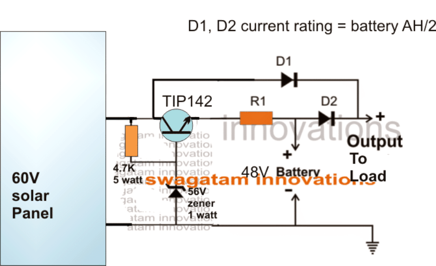
The emitter follower TIP142 ensures that the battery is never allowed to get overcharged above 55V.



Questions & Answers
Hi Swagatam,
Thanks for Solar charge controller circuit. The circuit appears to be little different than what i had requested. Let me reiterate the requirement again.
1. Solar panel should continue charging battery not beyond 56 V.
2. In the event of battery discharge, the charging process should resume again only when it reaches 48V. In other words hysteresis should be maintained.
3. Battery should continue supplying power to load when battery voltage remains in between 42 – 56V. When battery voltage reaches 42V (due to battery discharge) the load should be disconnected from battery supply. Once the load is disconnected, it should remain disconnected till the battery voltage reaches minimum 48 V during charging process.
Please confirm if the circuit works as above.
Best regards,
Deepak
Hi Deepak,
I'll update the modifications soon.
hi swagatam sir
this is srinivas
can i use this circuit for 12 volts 300ah battery if any changes please tell me sir
thanks & regards
Hi Srinivas
yes you can use it, just upgrade the mosfet for handling upto 50amps
for 12V battery the 22k resistors may be changed to 1k
hi swagatam sir
this is srinivas
what are the value of A1,A2 conected diodes
thanks
You can use 1N4148 for the diodes, 1N4007 will also work
Hi Swagatam,
I built charge control section of this circuit but somehow it is not working. My findings are:
1. MOSFET IRF 540 remains 'ON' always.
2. when 10K POT is varied the output of the comparater A3 changes but this change has no effect on state of MOSFET IRF540.
3. Tried with 3 new MOSFET but the result is same.
My guess is comparater voltage output is not completely '0' when its state changes to 'OFF' which is very important for MOSFET to function as a switch. I may be wrong. Please suggest me what else could be wrong. Thank you.
Best regards,
Deepak
Hi Deepak,
Try connecting a 1K resistor across the gate and source of the fet and check the response.
If it still doesn't work we may have to think about using a BJT stage between them.
Hi Swagatam,
Sorry it is not working even after placing 1K resistor across G-S. I have fried almost a dozen of FET playing with circuit but to no success. Please advice me further as this circuit is bothering me a lot. Thank you.
Deepak
Hi Deepak,
an fet will fry only if its voltage and amp specs are exceeded beyond the tolerable limits.
I cannot see any possibility in the diagram for this, as all have been taken care of.
The gate and the opamp supply pin is clamped with 12V zener diodes.
the drain is hopefully not getting loaded above the rated current by the battery in your design.
so there's no way the fet can get damaged.
I hope you are testing it with a battery connected, otherwise the IC will not get activated and will provided wrong results….so a battery is a must for the initialization of the circuit.
Hi Swagatam,
One more thing. Can i use IRFZ44N instead of IRF540 because i have about dozen of new IRFZ44N in my inventory and i want to use for this circuit if it is ok. Datasheet of both Mosfet seems almost same with only difference is in voltage rating. Please advise. thanks.
Deepak
For testing sake try a BJT, for example a TIP122 in place of the fet and see the response for the same. however TIP122 can tolerate only 2amp max, so use a smaller battery for the experiment.
also connect an LED in series with its base resistor, this will give an indication of the switching action accurately.
mosfets can be tried later on.
also do not connect the solar panel or any other supply at the input….just connect the battery and check the response of the base LED.
after this you may go ahead with the input supply and proceed with further testings
Hi Swagatam,
Yes i am testing with 48V battery and before connecting Solar input (2 units of 185W, 24i did make sure that the comparator output (and also LED) changes its state when 10K POT is adjusted. Doing so confirms me that at least comparator circuit it working fine, isn't it?
After that i connect the MOSFET. But i have found one interesting thing which i have reconfirmed with atleast several new MOSFET. The MOSFET is conducting and its state becomes 'ON' even if i do not connected 'gate' to the circuit. I have reconfirmed this problem even with several new MOSFET. This is very surprising which should not have been the case. Furthermore once this happens then i think MOSFET are getting damaged one after another.
I am stuck now and wondering if this cirucuit has really been built and test by anyone in this forum. Please advise me further.
Deepak
Hi Deepak,
It seems to be a different issue, not related with the circuit.
Because if the opamp output LED is showing the correct response means the circuit is performing correctly.
The mosfet could be blowing off due a static electricity, this could happen even with a bare touch of finger on the gate, although I have never faced this problem while handling mosfets.
If you want to get away from all this mess, then I would recommend you to convert the output stage wth BJTs or with a relay…eliminate the mosfets completely from the circuit and you won't have any such problems.
I'll update the article with a BJT circuit soon…
Hi Swagatam,
Please let me know what do I need to change in the above circuit to make it working for 24V (2 nos of 12 v @ 150AH) batteries.
Thanks for the circuit.
Regards
Gopal
Hi Gopal,
You won't have to change anything in the circuit, you can use it as given.
the supply pin resistor/zener can be eliminated if the opamps from LM324 are used instead of IC 741
Hello there,
It is requested to please help me design a circuit for 48 volts rectifier/charger to operate a buzzer on its failure, with a variable to adjust the dropout voltage. Circuit should mark the relay and sound the buzzer as soon as the charger voltage drops to 47 or 46 volts and it should unmark the relay and stops the sounding relay as soon as the voltage returns to 48 volts.
I know it is not a complex one, I have seen a circuit designed by you that is similar to my requirements, but a little tweaking is required i guess.
https://www.homemade-circuits.com/2014/04/48v-solar-battery-charger-circuit-with.html
your help in this regard is very appreciable
Thanks,
nadia
Hello nadia,
you can try the first circuit from the following article:
https://www.homemade-circuits.com/2012/08/make-this-48v-automatic-battery-charger.html
for the buzzer you can include a BC546 transistor with its base connected to the mosfet drain via a 10k resistor, emitter to ground and the relay across the positive supply and the collector of this transistor, the relay should be 48V rated as per the supply volatile.
Hello Swagatam,
I have read the thread you mentioned above, But my request here is that i need the buzzer to activate when the battery level reaches to 46v or 47v (adjustable) and it should deactivate the buzzer when the battery level regains its voltage to 48v.
can you help me in this regard please?
a detailed circuit would be v much appreciable pleassse
Regards,
nadia
Moreover load in around 10A and battery is 100AH
also load disconnection is not in the scope of my requirement. which makes it a bit easier i guess :/
regards,
nadia
Hello Nadia, I'll try to do it soon….and let you know, keep in touch in the meantime.
that would be soo kind of you 🙂
I have updated the required circuit in the above article, please check it out
Woah!!! that is so soo nice of you. I'll try to make the circuit ASA. meanwhile you canhelp me understand the physics of this circuit. I presume by seeing the circuit that it is in a comparator topology with two comparators; one for dropout voltage and other for upper thresh-hold.
You can help me understand the circuit more thoroughly as you have done in various different circuits. 🙂
Regards,
Nadia
Thanks, I have updated the setting up procedure at the end of the article, you can check it out.
The zeners at the base of the transistor can be replaced with LEDs for getting a visual indication of the proceedings, the polarity of the LEDs will be exactly opposite to the shown zener diode symbols.
well the circuit worked like charm. the feedback resistance for the required un-marking of relay was around 6.3 M ohm. but there is a glitch i must say, the buzzer starts at 46 v and stops at 44 volts. it must buzz below 46. but nevertheless it is good overall. thanks 🙂
thanks Nadia, I am glad to know it helped.
however the buzzer is supposed to start at 46V and stop at 48V (full charge) right?
I assumed you wanted to say this.
Anyway, for initiating the buzzer at lower voltages you can set the associated 10K preset (bottom opamp) accordingly so that the buzzer starts at 44V or at any other desired lower threshold..
Subhasish,
Please do it in the following way:
Initially keep the 22K perset disconnected from pin6 of the IC.
do not connect any load or the solar panel.
now feed 56V from the battery side through variable power supply unit.
next gently adjust the 10k preset such that the green LED just lights up.
this sets the high charge cut off for the circuit.
Now reduce the voltage from 56 to 44V, connect the 22K link and adjust it such that the green LED shuts off and the red LED lights up.
that's all the circuit is all set.
if the 22k preset does not work replace it with a 100k preset or a 220K.
connect a 3V zener diode at pin6 and connect the LEDs after the zener…as done in this circuit and then check the response again:
https://www.homemade-circuits.com/2012/07/make-6v-4ah-automatic-battery-charger.html
sure, please feel free to comment if you have further problems…
Subhasish, please read the previous instruction carefully….I suggested not to connect the load while adjusting the presets…here "load" refers to the battery…so do not connect the battery during the setting procedure, once the thresholds are set after that you can practically verify the results by attaching a discharged battery.
you can use a 1 watt zener diode at pin7 of the IC.
the voltage should be applied from the battery side…not from the panel side.
While setting up the circuit the input should be applied from the battery side through a variable power supply, please read the previous instructions again.
and you don't have to monitor any voltage, just monitor the LED switching as per the suggested procedures.
a 12V zener will do
when you rotate the preset as soon as pin2 voltage goes below pin3 voltage the output (pin6) will switch the LEDs from green to red…
pin3 is fixed at the shown reference 4.7 Volts with the help of the zener…so while adjusting the preset the voltage at pin2 will go below this reference 4.7V at some point…as soon as this happens pin6 can be expected to become high shutting of green LED and switching ON red LED.
Subhasish, did you set the 10k preset as per the above suggestion?
It needs to be done by applying variable supply from the battery side, NOT from the solar panel side. Unless you do this you won't be able to set it correctly.
make the second or the third circuit from the following link if you are not able follow the above circuit.
https://www.homemade-circuits.com/2011/12/how-to-make-simple-low-battery-voltage.html
BC547 is for switching OFF the load when battery volatge goes below the lower threshold
yes load and charging can be implemented together.
circuit is not practically tested, but if I were to make it I would do it without failing because I would know how to troubleshoot the small errors, if at all..
if you use a relay instead of the transistors, the same circuit can become extremely easy with a relay
I have updated the relay version at the bottom of the article, you can check it out
I have updated the diagram with all the required corrections, as far as possible.
please do it as per the new modifications….make sure you change all that's been updated in the updated diagram.
please check its datasheet to get a confirmed idea…
you can use a 100k preset in place of Rx, and adjust it for setting the lower cut off, as previously explained
The mosfets will start functioning when the supply is connected from the panel side,
after the 10k preset setting is completed from the battery side supply, connect the supply from the panel side and check all the functions
which LED do you see is ON after connecting the supply from the panel side?
Green LED ON will allow the load mosfet to switch ON and the lower mosfet to switch OFF….RED LED ON will do the opposite
..make sure to connect pin4 of the IC as indicated in the diagram.
If green is ON, then the base of BC546 will be zero.
confirm this first with a multimeter across base of BC546 and ground.
if base of BC546 is zero then mosfet gate should naturally have 12V…so it has to conduct.
check the voltage across mosfet gate and source
these will clarify everything
with your 48V batt is connected 60V input will have no bad effect on the relay…will do.
yes relay will provide you with the full 56V voltage for the batt
How's that possible? if green is ON means pin6 is zero, if pin6 is zero then from where the 0.7V get to the base?
connect another LED in series with the base of the BC546 (anode to 1K cathode to base)
and adjust preset again to force ON/OFF this LED,
now no need of putting the supply at the battery side because pin4 of the IC can access the ground from any side of the lower mosfet…so you can continue with the existing supply from the panel side.
the zener diode at pin6 was put to block this small leakage voltage so there should be no voltage at all at zener anode or may be the preset is not properly adjusted, or may be zener diode is wrongly connected.
please check all these issues…check voltage at pin6 and at zener anode
I had also suggested to connect an LED in series with BC546 base, that will instantly enable you to see whether the BC546 is switching or not