In this post I have explained an innovative automatic dual battery charger with isolator circuit for alternators and engines, which allows monitoring of the charge levels of two individual batteries, and switching them across the loads appropriately.
[New Entry] Single Op amp Dual Battery Charger Circuit
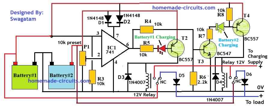
The circuit working for the above single op amp automatic dual battery charger circuit can be understood with the following points:
P1 preset is used to set the low battery changeover reference point.
Let's say it is set to 11V reference.
So, when the battery#1 voltage drops below 11V, pin#3 of the 741 becomes lower than pin#2 reference, causing the op amp output to go low.
The low output turns ON T2, which in turn activates the left relay. The left relay contacts now shifts to the N/O point allowing the charging supply to reach the batteryy#1. Battery#1 now starts charging.
In this situation, battery#2 is connected to the load via the N/C contacts of the right side relay.
When battery#1 is optimally charged above battery#2, or conversely, if Battery#2 voltage drops below battery#1 voltage, it causes the op amp output to flip and go high.
The high output turns OFF T2 and turns ON T4 via T3.
This causes the left side relay to turn OFF, and the right side relay to turn ON.
In this situation, the left side relay now begins supplying the load, and the right side relay starts charging the Battery#2.
In this way both the batteries are alternately charged and kept in a topped-up condition, through automatic sensing and relay changeover actions.
Solid State Dual Battery Maintainer Circuit without Relays
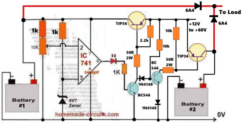
The next idea shown below was requested by Mr. Daz.
Technical Specifications
Very promising circuits you've always shared, actually I always visit your blog coz im also electronics hobbyist from Philippines ..
i have read many of your posted electronics design especially on battery charging circuits 🙂 its very simple and yet reliable and efficient circuits, building those circuits using your designs works great and thank you so much swagatam!
but until, i was thinking an solid-state automatic dual battery charger isolator for deep cycle agm 100ah batteries, i am using some of your design charging circuits and delay and relay techniques, but unfortunately, always got me an error...
what should I do sir?. can you guide me with my issues? thanks so much.
here is the step of how the circuit may do...
1. before starting, the two agm batteries 1&2 will combine in parallel connections to be used for starting the engine in order to provide smoother and more power to the start.
2.Then, once the engine is started, the battery 1 will automatically disconnect via a relay for automatic fast charging until float mode is reached.
3.while the battery 2 is connected, a voltage low level cut-off circuit will be monitoring its condition until its voltage reaches 11.5v,4.
When the low volt reaches 11.5v, the circuit will automatically trigger the relay connecting the fully charged battery 1 parallel with battery2.5.
after battery 1 is connected in parallel, a delay relay cut-off will disconnect of battery 2 and engage it for automatic fast charging and to float mode.6.a continuation cycle of relays, monitor, charging. that's it.
I hope you understand of what i mean.
hoping to hear from your sir. i hope you can help me with this circuits to make.
Thank you so much and more power to you sir!
The Design
Instead of addressing the two batteries as battery#1 and battery#2, I thought it was better identifying them as "charged battery", and "partially charged battery".
The proposed design of an automatic dual battery charger with isolator circuit for alternators may be understood with the following given points:
Initially due to absence of power, the two relays are held at their respective N/C positions which allow the two batteries to get connected in parallel with the load.
How the Batteries are Charged
Let's assume battery#1 as the charged battery, now when the engine is switched ON, both batteries provide their combined power to the alternator via the relevant N/C contacts.
As soon as the alternator starts, it powers the opamp circuit so that the opamps 1 and 2 which are configured as voltage comparators are able to sense the connected battery voltages at their relevant inputs.
As assumed above, since batt#1 has the higher voltage level, triggers opamp1 output high.
This in turn activates T1 and it's relay, which instantly disconnects battery#2 from the load.
Battery#2 now gets connected with the charger via the N/O contacts and starts getting charged at the relevant current.
At this point T1 executes two actions: It clamps the inverting input of opamp1 and non-inverting input of opamp2 to ground, latching their positions. It means the relays now hold their positions without any further interventions from opamp1 and 2.
In course of time, battery#1 starts getting discharged via the connected loads, and this condition is monitored by opamp3. The moment battery#1 charge reaches around 11.5V set by P2, opamp3 output goes low.
Since opamp3 output is connected to the base of T1, the above triggering instantly breaks T1 conduction resetting opamp1 and 2 into its original situation allowing them to yet again track the battery voltages.
This time battery2 being the one having higher potential activates opamp2/T2 and the lower relay.
The actions quickly disconnects battery1 from the load and connects battery#2 with the load.
Opamp4 now monitors battery#2 condition until its voltage also falls below the 11.5V mark when the situations yet again reverts.
The cycle continues as long as the engine and the load remain in the discussed chain.
The capacitors C1, C2 ensure a smooth transition between the relay switching.
Circuit Diagram
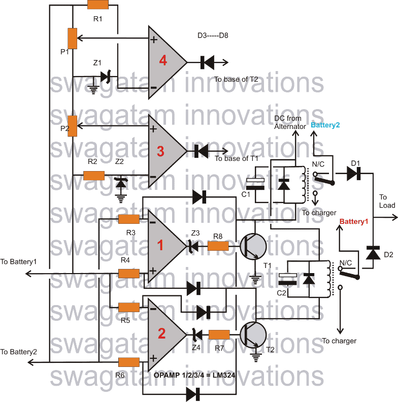
Note: Connect the emitters of T1/T2 to ground through 1N4148 diodes, this is important otherwise the opamp3/4 outputs won't be able to switch OFF the BJTs correctly.
As we can see in the above automatic double battery charger with isolator circuit, the relay N/O contacts are responsible for the required charging of the connected relevant batteries.
Since these batteries need to be charged with an "intelligent" charger, the system should be a step-charger kind of unit.
One such circuit has been discussed in this 3 step battery charger circuit, which may effectively employed here for the proposed method of charging both the batteries.
Parts List
All resistors are 1/4 watt CFR
- R1, R2, R7, R8 = 10k
- R3, R4, R5, R6 = 1M
- P1, P2 = 10k presets.
- D1, D2 = asper load current.
- D3---D8 = 1N4007
- All zener diodes = 4.7V, 1/2 watt
- T1, T2 = 8050
- C1, C2 = 220uF/50V
- Relays = SPDT, 12V, 30 amps contacts
- Opamps = LM324 (see datasheet)
Dual or Double Battery Charger using IC 555
The following paragraphs explain a simple automatic double battery charger circuit from a single power supply. The idea was suggested by "Superbender" I have explained the details.
Technical Specs
Thanks for the great circuits. I am looking forward to start putting one together for hibernating my RVs battery over the winter.
However, can I exchange the transformer + diode bridge with the +15V DC power output from an old PC power supply, i.e a switched power supply?
I don't see any reasons why not, but don't know too much about the charging restrictions for 12V Lead Acid Batteries.
I think I'll be moving down the path with a switching power supply that is rated for 5A max current. However, I am wondering if I can charge 2 batteries at the same time.
I have an older VW camper that has an auxiliary battery as well as a starter battery.
Over the winter I'd like to keep both batteries happy and your schematic seems to be promising to achieve that. The batteries are not connected to each other when the car is off.
Do you think it is possible to use only one power supply, but two NE555 schematics to achieve this? I am thinking that I could use one NE555 schematic per battery, probing for voltage levels and controlling individually when each battery is charged.
I am also thinking to put a diode into the current path to the battery so that, when both batteries are charging, the current can never flow from one battery to the other.
According to the spec sheet, the 44 Ah auxiliary battery that I am going to buy has a max charging current of 12A.
The other battery should have about 75Ah capacity. My interpretation of those values is that both batteries can handle the full 5A current when only one is charged.
If both are charged simultaneously, they'd simply take longer and current will distribute itself according to the voltage levels of the battery.
Obviously I am trying to prevent buying two switching supplies (the PC power supply actually didn't offer 15V when I checked), which would keep the cost to a very interesting level => ~$30 vs. ~$55 for a system with two PS or vs. about $90 for buying two chargers.
Looking forward to your thoughts on this.
Thanks again
Superbender
The Design
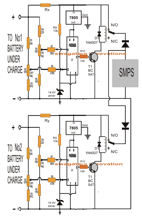
The proposed automatic double battery charger circuit from a single power supply shows two identical stages made by using the IC555. These stages are basically responsible for controlling the lower and upper charging thresholds of the connected batteries.
The SMPS which is the common power source for both the 555 stages supplies power to the batteries via the individual diodes and the relay contacts of the respective 555 stages.
The diodes make sure that the power stay well isolated from the two stages.
However the crucial part of the circuits are the two resistors Rx and Ry which are the current limiting resistors for the two stages.
These resistors ensure the correct specified amounts of current to the respective batteries This further ensures that the SMPS is loaded uniformly across the connected batteries.
Rx and Ry should be calculated as per the AH ratings of the batteries with the help of Ohm's law.
Schematic
Another Simple Split Battery Charger
In the following paragraphs we investigate another interesting twin or split battery charger circuit with auto-changeover illustrates a method through which two 12V lead acid batteries can be charged and discharged in tandem by switching them appropriately across the charging voltages and load alternately.
This ensures that the load receives a continuous supply of power irrespective of the actual source conditions such as a solar panel, wind generator etc. The idea was requested by Mr. Mohammad Zain.
Design Objective
I am looking for a automatic 12 volt lead acid battery charging circuit, Which indicates when the battery is full and when it is out of charge.
Or if you can help me design a charging circuit that will use two batteries that is it will charge one battery at a time so when it gets full it will switch to the other battery
Your help will be really appreciated .
Working Details
The discussed split battery charger can be studied through the following detailed explanation:
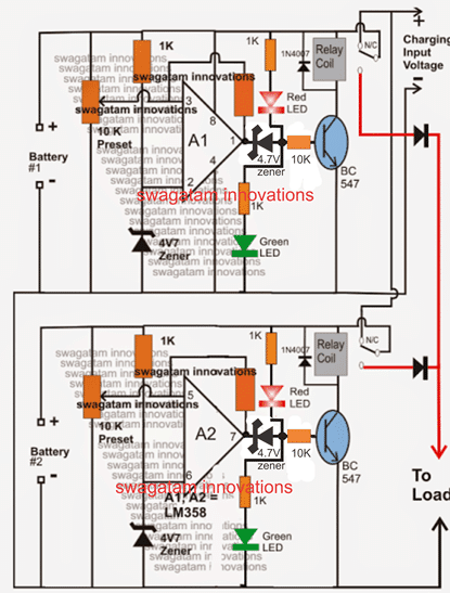
Referring to the circuit diagram, two identical opamp stages A1/A2 can be seen incorporating the IC LM358. Both the opamps are rigged as voltage comparators.
A1/A2 are basically configured to detect the over voltage and low voltage thresholds of the respective batteries and to switch the corresponding relays for initiating the required cut-offs when the relevant conditions are detected. This is sensed with reference to their inverting input voltage levels fixed at the corresponding zener voltages.
The over charge cut-off threshold is set by appropriately adjusting the 10k preset associated with the non-inverting inputs of the battery.
The feedback resistor across the outputs and non-inverting inputs of the opamps determine the hysteresis levels which in turn decide the low battery restoration so that the relevant batteries begin charging once the corresponding lower thresholds are crossed.
Suppose battery#2 is initially fully charged, and battery#1 is being charged through the N/C of the A1 relay stage.
The connected load at this situation receives the voltage through the N/O of A2 relay since it's already in a disconnected state due to full charge condition of battery#2.
Now let's assume after a period of time battery#1 gets fully charged, A1 output goes high triggering the connected relay driver stage which disconnects the charging voltage to battery#1 by shifting from N/C to the N/O contact.
At this instant both the batteries get connected with the load reinforcing the supply to the load.
However, sooner or later battery#2 reaches its lower discharge threshold, forcing A2 to restore the charging process by flipping its relay from N/O back to N/C.
Battery#2 now gets into the charging phase leaving battery#1 to handle the load, the operations keeps repeating as long as the system stays switched ON.
For ensuring a balanced switching responses from the two stages one battery must be completely discharged while the other fully charged at the beginning when the proposed twin battery charger circuit is first initiated.
Circuit Diagram
Simplified LED Connections
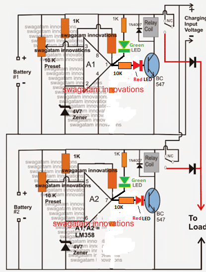
For ease of testing and optimization please modify the positions of the LEDs as per the following diagram. The zener diodes at the transistor bases can be eliminated in this case.
How to Test
We will refer to the above modified diagram for the set up procedure.
As we can see, the A1 and A2 stages are exactly identical, therefore these two stage should be set up separately.
Let's begin with A1 stage adjustment.
- Initially keep the feedback resistor across the op amp output and preset disconnected.
- Rotate down the slider arm of the preset to ground level (0V).
- Connect an external DC of around 14.3V from the "battery side". You will see the green LED light up.
- Now, carefully rotate the perset towards the positive side until the green LED just shuts off and the RED LED lights up, this will also switch ON the relay.
- THAT'S ALL! Your circuit is set now. Reconnect the feedback resistor, which could be any arbritary selected value between 100K and 470K.
- Repeat the procedure for the A2 circuit stage and integrate the two stages with the relevant batteries for a practical test.
The FEEDBACK resistor decides at what lower threshold the battery will start charging again, and will need to be fixed with some trial and error. 100K would be a good value to start with.
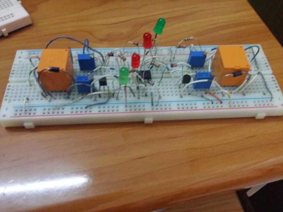
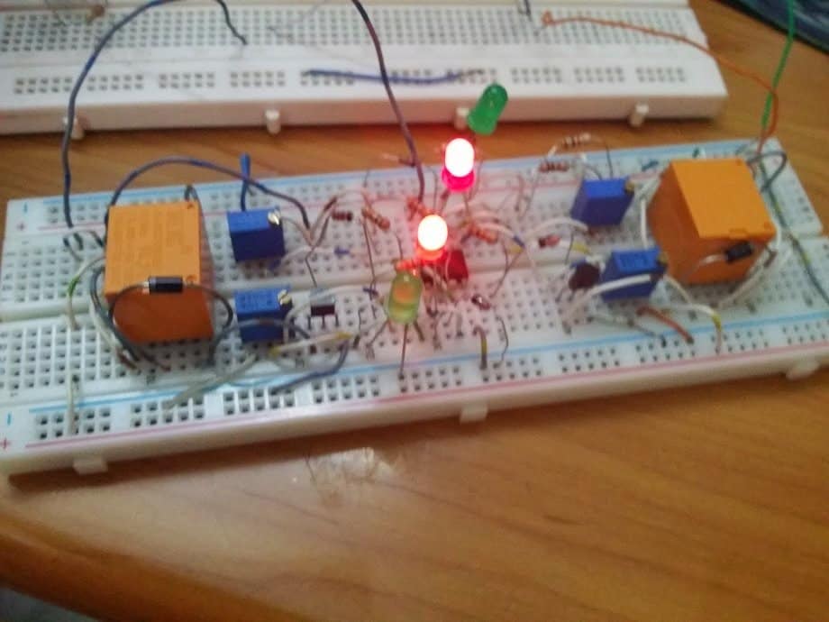
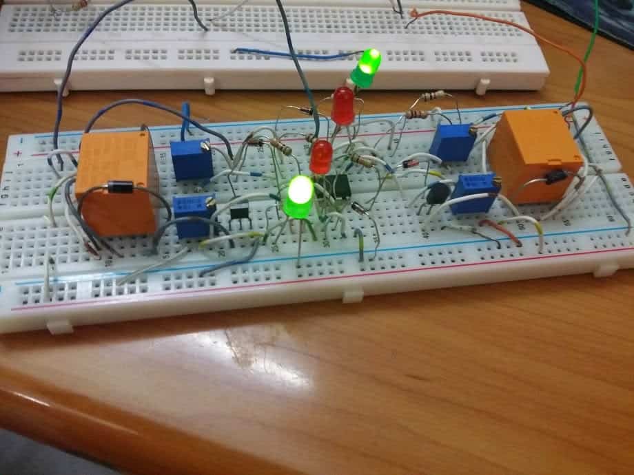
The above explained selectable 12V battery charger circuit was built and tested successfully by Mr. Dipto a dedicated member of this blog.
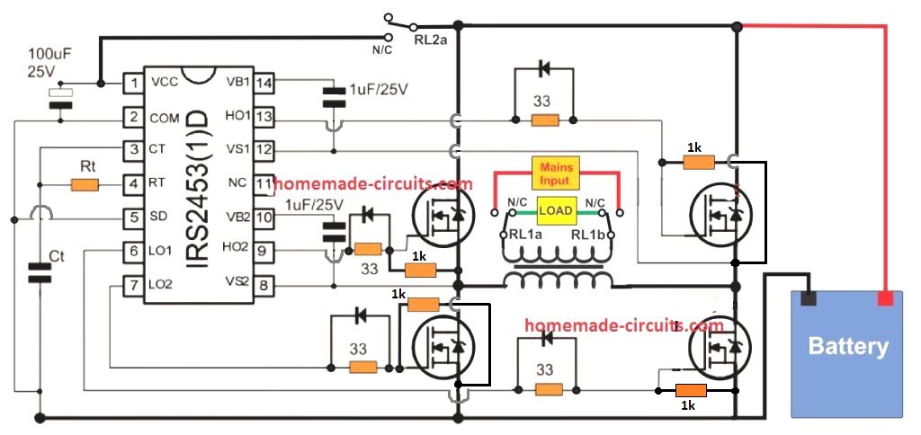
The implementation details may be witnessed in the following images of the prototype, sent by Mr. Dipto.



Questions & Answers
I need this automatic battery charging and selection circuit to be modified from 12V to 72V DC operation.
The system should:
Operate with a 72V DC battery system
Include a voltage regulation stage to step down 72V to 12V for the control circuit (op-amp/logic)
Replace the 12V relay with a 72V DC relay
Replace BC547 / BC557 transistors with high-voltage transistors or MOSFETs
Recalculate and modify resistor values so voltage sensing and thresholds match a 72V system
Include proper protection (flyback diodes, reverse-polarity protection, over-voltage protection)
Maintain automatic switching between Battery 1 and Battery 2 without unsafe simultaneous charging
Be stable, safe, and suitable for continuous 72V operation
If you want, I can also:
Make it more technical
Prepare a component list
Draw a simplified 72V block diagram
Just tell me 👍
Hey, thanks!!
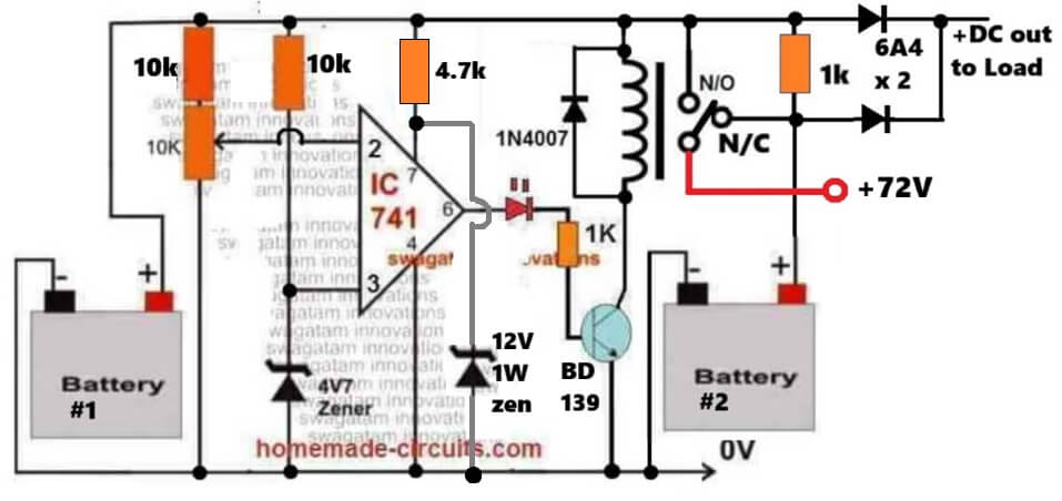
Here’s a simple design you can try that meets your specifications:
What is the minimum voltage? How can it be adjusted to asymmetrically always charge battery #1 unless battery #1 is full, and always charge battery #2 otherwise instead of latching and switching back & forth in a way affected by battery #2? (I would like it if it was cheaper, simpler, low-quiescent-current, and reliable with low current (e.g. 100% solid-state). I don’t need to charge with >500mA, and the batteries will draw <5A with no restriction.)
Here, is a very simple and effective dual battery charger/manager circuit, you can build:
https://www.homemade-circuits.com/wp-content/uploads/2025/06/simplest-dual-battery-charging-manager-circuit.jpg
Can the relay be replaced with transistors for improved reliability?
Relay is more effective, stable and efficient than transistors for our previously referred diagram.
A relay coil’s current draw adds up over time pretty quickly. A MOSFET’s gate’s does not. A relay’s contacts wear out too.
A good quality correctly rated relay contacts will wear out after maybe 20 to 30 years of continuous use, you can change the relay after every 25 years, ok? Relay coil current is negligible compared to the supply provided for the batteries. MOSFETs can be duplicate and burn unpredictably. MOSFETs cannot be configured for dual battery easily…
Not if the relay chatters or the batteries are fully charged (standby use). You lose something either way. For your stated application (big batteries cycling based on renewable energy without grid-tie) the relay is great, but I need help with my lower-energy application.
Relay chattering can be simply solved by adding a 100uF capacitor across the relay coil, or by adding a single hysteresis resistor across the opamp pins.
Here’s a fully solid state transistorized version of a dual battery charger circuit:
https://www.homemade-circuits.com/wp-content/uploads/2025/07/solid-state-fully-transistorized-dual-battery-charger-circuit.jpg
How would it be adjusted for charging packs of 3 rechargeable AAs, each in series?
You can do it by adjusting the maximum charging voltage to the batteries, and the cut-off threshold, as per the specifications.
Which specifications say how to make the needed adjustments?
Your input power supply must be regulated to supply the constant charging current and voltage to the batteries.
Initially you can connect this supply from the battery#1 side and adjust the opamp preset, so that the opamp output LED just turns OFF.
Thanks!
hi swagatam
I need help with the following project circuit.
Problem Statement
A car main battery normally runs flat when the lights and or music are left ON (un/intentionally) for longer durations or when over-used while the car is OFF. This warrants a device that can be installed in the car to monitor its primary battery (>40Ahr) voltage to enable it to be used solely to crank (start) the car and to safely charge a secondary battery (e.g. 20 Ahr) at a maximum of 2A, which will be used for the car accessories (lights, music etc) for at least an hour while OFF.
Objectives
The idea is such that, when the car is driving, the primary battery is being charged normally via the alternator, which in turn charges the secondary battery at max 2A. When the car is OFF, the primary battery voltage is monitored and when it drops below a certain value, say 12.5 V, the primary battery is automatically disconnected, while the secondary battery is automatically connected to now supply power to the accessories for at least an hour. When the secondary battery drops below 11.5V, it’s disconnected to save some power for at least a day for the car alarm system, as well as for the central locking system.
key results,
A car dual 12V lead acid batteries charging device.
Secondary battery must be isolated from the alternator.
The measureable parameters may be displayed on a touchscreen or web server.
Hi Asrza,
I think the first design shown in the above article can be easily modified to suit your application. However, your last requirement regarding displaying on touch screen and web server looks difficult to me.
Hi Swagatam,
I want to make a double 6.4 or 7.5 volts battery charger switch. Meaning, I want the 2 batteries to be isolated from each other. Switching from charging state to “operation” state when fully charged, but when fully charged should be totally disconnected from the charging source to make sure I do not get any noise (the battery will power audio equipment and I want to isolate myself from any grid noise. I would try to make a simple breadboard with it. I can use any type of batteries, but best would be 7.2 li-ion as they are smaller. Thank you in advance.
Hi Cyrille,
You can try the first circuit concept from the above article. It suits your suggested application specifications and should be able to fulfil it.
I am surprised that a manufactured unit for this circuit hasn’t been produced for retail purchase. For an off grid solar set-up with 2 or more deep cycle lead acid batteries this is the best circuit for ensuring that power will always be available, (at least if the sun shines a little bit every few days), maximizing the lifespan or condition of the deep cycle batteries while also allowing them to be of different sizes, ages, health, etc. If there is such a unit available i would like to know because i have not learned how to read the design schematics for this stuff.
Thank you! I appreciate your valuable feedback! These units are available in online stores like amazon.
I have not seen any as a single unit. I’ve seen voltage sensitive relays, isolators, etc. I did find one mppt controller featuring inputs for connection to a start battery and ignition switch so a running vehicle could also contribute charge, which is really cool but i already have a nice mppt controller. Maybe you can share a link? Thanks
Yes, it seems you are correct. When I tried searching for “Buy Dual lead acid battery charger”, I could not get any proper results to support my search query….
Very nice site