In this post I have explained a high current Li-Ion battery charger circuit which can be used for charging any high current, such as 2S3P, 3S2P battery packs. It can be also used for charging other similar high Ah rated Li-ion battery from a car or a truck battery. The idea was requested by Mr. Neil
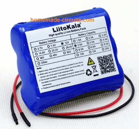
Charging a 8800 mAh Li-Ion Pack
This is perhaps very cheeky of me to ask for your help, but my design skills are limited in electronics and as a volunteer my budget is limited.
I am a volunteer for a local Search and Rescue organisation (Suffolk Lowland Search and Rescue), we are on call 24hrs a day 365 days a year, our work involves finding anyone who has gone missing in Suffolk (and bordering county’s).
Search often take place during the hours of darkness and we have a particular need for good torches, which need to be ready for action at a moments notice.
I am part of the mountain bike rescue team, we cover ground very quickly and can search paths much faster then foot teams, lights are again very important and I hope this is where you can help.
I have recently bought a Cree LED light for my bike, it is powered by a 8.4v Li-ion 8800mAh battery pack, I have 2.
These units came with a mains powered charger (240v UK) and what I would like is to be able to charge them in the car where the bike is kept.
I noticed you have already designed some charging circuits for this type of battery and I wonder if you could modify your design to be able to charge from a 12v car circuit to these specification batteries.
The car circuit will be switched with the ignition. I am very capable of constructing the circuit, it’s just my design skills that are limited!
I very much appreciate anytime you spend on this, it will help not only me, but potentially any lost sole in Suffolk.
Kindest regards,
Neil.
Simplest Solid-State Design Using an Op-Amp (Recommended)
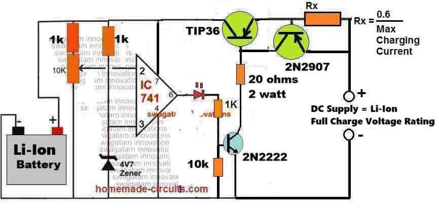
The following circuit of a high current Li-Ion battery charger circuit can be efficiently used for charging all types of Li-Ion and Li-Po batteries, safely. Because this design, despite being simple, includes a constant current feature and also an automatic cut-off feature.
How it Works
Initial Charging Phase:
When the battery is connected and its voltage is below the full-charge level, the IC741 comparators output is high.
This activates the TIP36 allowing current to flow into the battery through Rx.
The charging current is controlled by Rx to prevent overheating or damage to the battery.
Current Limitation:
The value of Rx determines the maximum current delivered to the battery. This prevents overcurrent and ensures safe charging.
Voltage Monitoring:
As the battery voltage rises and approaches the full charge threshold then the non-inverting input (pin 3) of the IC741 exceeds the reference voltage at the inverting input (pin 2).
This causes the IC741 output to switch low turning off TIP36 and stopping the charging process.
Automatic Cutoff:
When the charging stops, the battery is protected from overcharging. The circuit automatically resumes charging if the battery voltage drops below the threshold.
Calculations for the Design
Selection of Rx (Current Control Resistor):
The resistor Rx limits the charging current Imax as per the formula:
Rx = 0.6 / Imax
For example:
If Imax = 1A:
Rx = 0.6 / 1 = 0.6 Ohms
Ensure the power rating of Rx is sufficient to handle the current:
P = Imax2 * Rx
For Imax = 1A and Rx = 0.6 Ohms:
P = 12 * 0.6 = 0.6 W
Use a resistor with a power rating slightly higher than the calculated value (e.g 1W or 2W).
TIP36 Base Resistor
The base resistor ensures sufficient base current for TIP36:
Ibase = Ic / hFE
Where:
- Ibase = Base current
- Ic = Collector current (equal to Imax)
- hFE = Current gain of TIP36 (typically it is around 30)
For example, lets say if the required collector current Imax = 3A:
Then base current Ibase = 3 / 30 = 0.1 A (100mA)
Then we can calculate the base resistor value as:
Rb = (Vout - Vbe) / Ibase
Where:
- Vout = Output voltage of IC741 (approx. 11V)
- Vbe = Base-emitter voltage of TIP36 (approx. 0.7V)
Rb = (11 - 0.7) / 0.1
Rb = 10.3 / 0.1
Rb = 103 Ohms
How to Setup the above Design
First make sure the wiper of the 10K preset resistor is pointing down towards the ground. After that, you need to add a sample voltage from the BATTERY SIDE.
It's really important that this voltage comes from the battery side and not the transistor side. But remember don’t connect an actual battery while you’re testing.
The sample voltage should be a little higher than what the battery's full charge level is. When you do this you should see the LED light up really bright.
Then slowly turn the 10K preset until the LED goes out completely. Once that’s done you can disconnect the power supply and hook up a dead battery. You’ll see the red LED turn on.
Next connect the right amount of full charge voltage from the transistor side to start charging the battery.
When the battery hits the set cut-off point for charging, the red LED will turn off which means the battery is fully charged, and is cut-off from the charging supply.
Using LM338 with Op-Amp
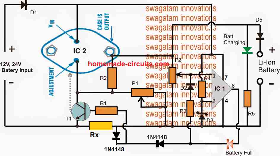
The shown high current Li-Ion battery charger circuit is featured to charge any Li-ion battery upto 5 AH with the shown IC2, or for 10AH batteries if IC2 is appropriately replaced with a LM396
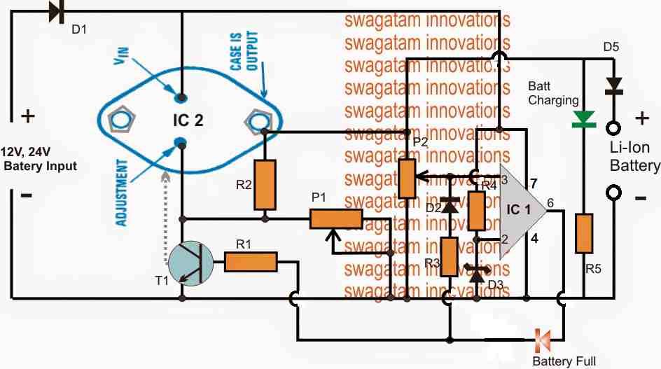
The LM338 IC2 is a versatile voltage regulator IC which can be specifically configured for charging Li-Ion cells with the essential features such constant current and constant voltage.
The above design is configured as a constant voltage Li-ion charger, since we assume that the input supply to be a constant current.
However in case the input supply is not current limited, the IC2 can be enhanced with an effective constant current feature. We will discuss this at the end of this explanation.
The design consists of two fundamental stages, the IC2 voltage regulator stage and the IC1 over charge cut-off stage.
IC2 is configured in its standard voltage regulator form, where P1 functions as the control knob and can be adjusted to generate the required charging voltage across the connected Li-ion battery at the output.
IC1 pin3 is the sensing input of the IC and is terminated with a preset P2 for facilitating the over charge voltage level adjustment.
The preset P2 is adjusted such that when the battery reaches its full charge value, the voltage at pin3 just becomes higher than pin2, resulting in an instant high at pin6 of the IC.
Once this happens the high from pin6 latches on to pin3 with a permanent high via R3, D2, freezing the circuit in that position. Remember this latching network is optional, you can remove it if you wish, but then the the Li-ion battery will not be permanently cut-off, rather intermittently switch ON/OFF depending on the full charge level threshold of the battery.
The above high is also delivered at the base of the BC547 which immediately grounds the ADJ pin of IC2 forcing it to shut down its output voltage thereby cutting off the voltage to the Li-ion battery.
The Red LED now illuminates indicating the full charge level and the cut off conditions of the circuit..
Circuit Diagram
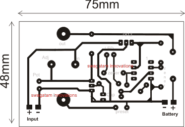
PCB Design
Parts List fro the proposed high current 12V/24V li-ion battery charger circuit
- R1, R5 = 4K7
- R2 = 240 Ohms
- P1, P2 = 10 K Presets
- R3, R4 = 10K
- D1, D5 = 6A4 diode
- D2 = 1N4148
- D3, D4 = 4.7Vzener diode 1/2 watt
- IC1 = 741 opamp for 12V input, LM321 for 24V input
- IC2 = LM338
How to Set up the circuit.
- Initially do not connect any battery at the output, and rotate P2 so that its slider touches the ground end, in other words adjust P2 to make pin3 to zero or ground level.
- Feed the input voltage, adjust P1 for getting the required level of voltage across the output where the battery is supposed to be connected, the green LED will be lit up in this position.
- Now very carefully move P2 upwards until the the red LED just illuminates and latches in that position, stop moving P2 any further, confirm with green LED shutting of in response to red LED illumination.
- The circuit is set now for the required high current Li-ion charging from a car battery or any 12/24V source..
Adding a Constant Current Feature in the above Design
As shown below, the above design can be further improved by adding a current control feature, which makes the proposed high current Li-ion charger circuit perfect with the features of CC, and CV, that is with constant voltage and constant current attributes.
Note: The latching of the op amp is not compulsory, hence the D2 and R3 can be removed, and the circuit will still work nicely and automatically cut-off when the battery is fully charged.
Simplified Design
While the above explained circuits are great with their features and working, the use of LM338 makes the design a bit complex, and costly.
A little tinkering reveals that the application could rather be implemented using only a single opamp and a BJT based current control as shown below:
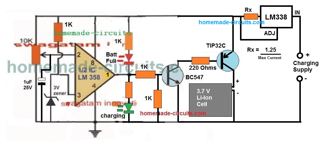
A 1uF capacitor is introduced at the inverting input of the IC, which ensures that the IC always starts with its output at positive high when powered. This in turn allows a guaranteed switch ON of the output transistor, and enables the connected battery to lock in with the charging process.
The concept has been tested thoroughly, the video proof can be seen here.
22.2 V Li-Ion Battery Charger Circuit
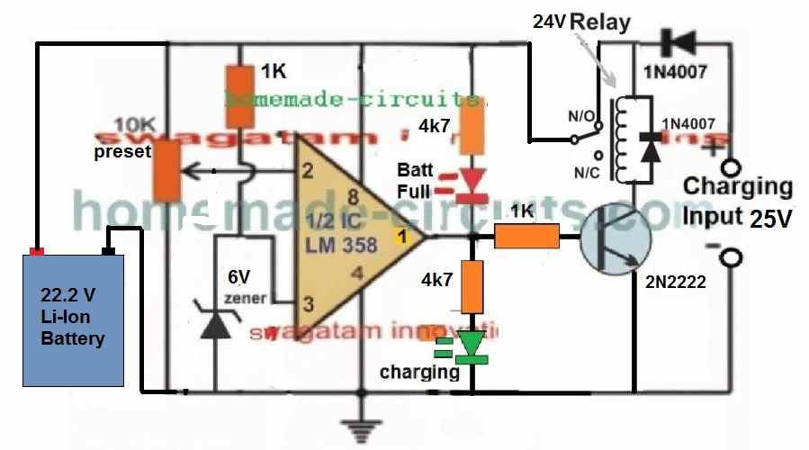
The following diagram shows a simple yet very accurate Li-Ion battery charger circuit with cut off. This charger can be used for charging a 6S Li-Ion battery rated at 22.2V.
WARNING: IN ALL THE ABOVE CONCEPTS, TEMPERATURE REGULATION FOR THE BATTERY IS NOT INCLUDED, SO PLEASE MAKE SURE TO ADJUST THE CURRENT TO A LEVEL WHICH DOES NOT CAUSE THE BATTERY TEMPERATURE TO REACH ABOVE 40 DEGREES CELSIUS.
How it Works
Let's assume there's no battery connected at the left side of the above circuit, and a charging input is switched ON from the right side of the circuit as indicated in the diagram.
In this situation, we find that since the initial relay position is on the blank N/C point of the relay, so the circuit cannot get powered, and so nothing happens to the circuit, and the circuit stays unresponsive and dormant.
Now, if a discharged battery is connected on the left side of the circuit as shown, the opamp gets powered through the battery voltage and its input pin#2 detects the discharged state of the battery voltage, which could be lower than the pin#3 reference of the IC, as per the setting of the preset.
So this instantly causes the output pin#1 to go high (because pin#3 potential is higher than pin#2 of the IC).
The high from pin#1 turns ON the transistor and the relay, causing the relay contacts to move from the default N/C points to the N/O points.
So now the charging supply is able to quickly get connected with the battery through the N/O contacts and the battery starts charging. In this situation, the input charging voltage is dragged down to the discharged level of the battery....and the battery now slowly begins charging.
As soon as the battery gets charged to its full charge level, the pin#2 potential now becomes higher than the pin#3 reference of the opamp, which immediately causes the output pn#1 voltage to become 0V, turning off the transistor and the relay.
The relay contacts now return back from the N/O point, to its default N/C point, cutting off the charging supply to the battery...
How to Setup
Initially, keep the preset fully rotated towards the ground side.
Connect a diode between the relay coil and the opamp positive rail as given in the following diagram:
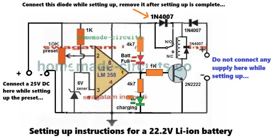
Now, connect a suitable input charging supply around 25V on the right side of the circuit.
So now 25V gets applied to the circuit. And you will see the relay clicking ON, and the green LED switching ON.
Now, slowly adjust the preset until the relay turns OFF, and the green LED shuts off, causing the red LED to turn ON.
That's it, your circuit is fully set now for charging any high current 22.2V Li-ion battery or any other battery rated between 3.7V and 29.6V Li-ion battery. Seal of the preset with any suitable glue....
Next, you can remove the power supply from battery side and connect it at the right side which is input charging side of the circuit.
Finally, connect any discharged battery from the left side of the circuit, as indicated in the diagram, and start charging the battery with high current, and an automatic full charge cut off..


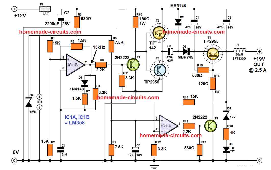

Questions & Answers
hello
in the first circuit when the battery is discharged, tip36 is on and thr Rb (20 ohm) is concuming the power of battery. is that right?
Hi, No… 20 ohm is getting supply from the input charger DC supply, through the emitter pin of TIP36. This resistor must be calculated based on the Ah rating of the battery.
Thank you for previously publishing the current voltage current adjustable circuits of the LM 337-338-350 integrated circuits. Could you publish the same circuits in LM337, thank you.
Thank you Mehmet,
You can find a few designs using LM337 in the following article:
https://www.homemade-circuits.com/how-ic-lm337-works-datasheet-application-circuits/
Hi brother, in 22.2 v lithium battery charging circuit ,the diode which connected between input volts 25v
is it is connected to the N/O pin or N/C
pin , because in picture its connected N/C but it is written N/O (normal open)
Hey Bro, The input supply diode is connected with one terminal of the relay coil, and the N/O contact.
hi, I assembled this circuit both LEDs on/off while adjusting the pot 10k, showing charge start and stop
but here some time missed relay on/off , though proper output from ic pin1 to 1 k for transistor base
but unable to operate relay
Hi, It is because the relay coil is not getting any supply. Please make sure to keep the preset initially to the ground level, next connect a 25V input charging supply from the right side end, and proceed as per the following diagram:

Thanks, dear 🙏 , yes I checked the circuit , relay will energized only on charger connection , because no +ve for it it connected to batteries.
thanks bro
Prefect Bro! Glad you could figure out the issue….let me know if you face any further issues with the circuit…
Hi, in the updated 22.2 v battery charging circuit you have mentioned IC pin#6 as output , i think it will be pin#1 in the said circuits , Thanks
Thank you for pointing out the mistake!! Yes, for this LM358 IC it should be pin#1, I mistakenly assumed it to be the IC 741 whose output pin is pin#6.
I have corrected it now…
Good afternoon Mr. Swagatam,
I’m fairly new to PCB design (6 months).
Do you think this circuit will work for a BB2557/U, 99 Wh 6.8 Ah, Rechargeable Lithium-Ion Battery? Nominal Voltage is 14.4V for one cell and 28.8V for both cells. Attached is a link to the battery I am trying to charge.
I’d also like to be able to use the battery to power things when it is not charging.
Please let me know your thoughts and any tips you may have for this battery.
Thank you.
Hi Aaron,
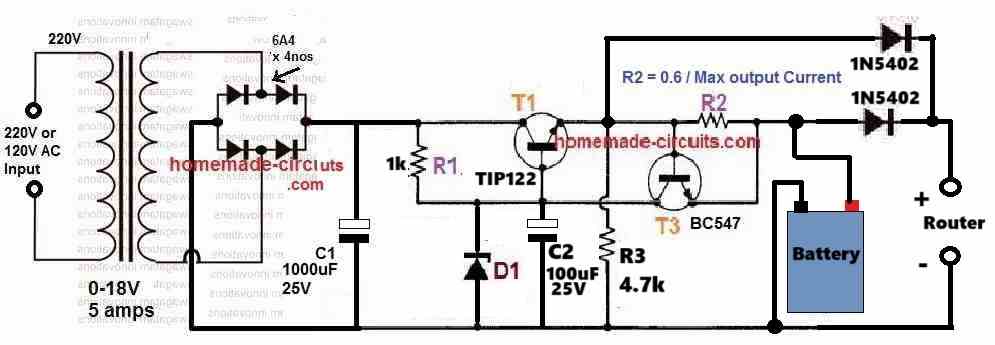
You can charge all Li-ion and Lipo batteries using the above circuits safely, by appropriately adjusting the current limit.
To be able to operate a load simultaneously, you can use the following design:
Make sure to select a zener diode such that the output across the battery points is slightly lower than the full charge voltage specification of the battery.
Fix this without connecting any battery.
For example if the battery full charge voltage spec is 12.6V, then adjust the zener value to get around 12.4V across the battery points (without battery connected).
R2 must be fixed as per the given formula.
R2 = 0.6 / Max permissible current
For a Li-ion battery the max permissible current can be around 50% of its Ah value.
Thank you so much! I’ll build this and run some simulations.
You are most welcome!
The simulations turned out great.
One more question for you. You said this will charge and operate the load simultaneously. Does this mean the battery is not providing the power to the circuit? I’m trying to have the battery as a backup in case power to the system is disrupted. That way the battery will kick on and provide the power needed to operate until depleted or until power from the original circuit is restored.
Thanks for the update.
The load will always keep getting the operating power from the input mains. If the input mains is removed or fails then the load will start getting the power from the battery.
Thank you for clearing that up for me.
Glad I could help!
Dear Mr.Swagatam,
I am viswanathan from India reg. my Milagrow Floor cleaner using 14.8 v lithium battery. Now it is not working. I am based Electronics. Aged 77 yrs. No person is repairing the Milagrow machine in Chennai. Would you please forward the working diagram of Power supply and your valuable suggestion to rectify the defect in the Milagrow Floor Cleaner machine.Thanks in advance.
Viswanathan SA
Thank you Viswanathan S.A, for your question,
Are you looking for a Li-ion battery charger circuit for a 14.8 V Li-ion battery, if yes, then I can certainly help you with a proper working circuit diagram. In that case i will also require the Ah value of the battery.
Please let me know your thoughts on this….
Please what is the safe charging voltage for 11.1v lithium set, full battery cut off and low battery cut off voltage. Thanks
The safe full charge level is 12.3V which will not require an auto-cut off. If you have an auto cut off facility then use 12.6V.
Low battery limit is 9V.
Please will the 12.3v be the charging voltage or what level?
It is the charging voltage that must be fixed and never exceeded.
Thanks Swagatam, please advise, how to safely charge without a BMS. Is it advisable and possible.
It’s definitely possible to charge any battery optimally and safely without a BMS.
In your case keep the full charge level “fixed” at 12.3V, and use a current level that’s 50% less than the mAh rating of the battery.
Please, I have 2 different sets of lithium batteries, a set charges battery faster and retains better, the other charges too slow but retains not as good. Why is it so, sir?
Hi Daniel, without checking the schematics of the two chargers it can be difficult for me to figure out the difference in their working specifications. So if possible please the schematic details of the two chargers.
I meant charging the 2 new sets of lithium batteries with a transformer based charger, the outcome was significantly different
You can try connecting an ammeter in series with both the batteries and monitor how much current each of the batteries consume while charging, this will instantly show you the difference between the two battery conditions.
Yes, thanks for this guide, the better battery
set draws 500mA while the other battery draws 1.8Amps but poor outcome. I don’t understand this
I got the 3-5A charging current but why at the rate I used above , the battery sets behaved differently with different responses.
The amount of current the battery consumes will entirely depend on the specific battery, we cannot force the battery to consume the amount of current as we desire.
Can you please tell me the Ah rating of the batteries?
12ah new lithium battery set
A 12 Ah Li-Ion battery will require around 4 to 10 amp current, to charge effectively.
Please try increasing the supply current to at least 3 or 5 amps and check the results.
For C10 / 150ah lead acid battery ; max current is 150/10=15amp
But for 3C / 150ah Lithium battery ; max current is 3X150=450amp
There is division but here is multiplication.
Am I Correct?
Please use this formula to calculate the C rate:
C rate = current / battery capacity
bat CAP is 100ah.
max current=3C=?
Max current=0.5C=?
Max current cannot be 3C.
0.5C = 50 Ah
which company mppt is best for 1kw 24v panel and using lithium battery 24v 50ah 1c.
Sorry, I have no idea regarding which MPPT company is the best…
I have 7S 18650 50ah lithium battery.
which solar mppt will be best suitable for this.
some mppt are for 6s also.
What is the voltage range for 7s.
I am confusing for 6s vs 7s.
no one mentions if mppt is for 6s or 7s.
hope you fine
7s = 7 x 3.7 = 25.9V and its full charge level would be 7 x 4.2 = 29.4V, or simply 29V. With reference to these specifications you can select which MPPT is suitable.
I have two lithium bat of 24v 50ah with bms.
can I connect in parallel?
hope you fine!
You you can connect them in parallel.
Sir I want to charge 3s2p lipo battery using 12v 5A smps which can be adjustet to 12.6v. I need only indicator circuit without ic2 lm338. Is it possible ? And sir how to limit charging current so that battery will not heat up. Plz help me.
Rupjyoti, for low voltage indication you can use the following circuit:
https://www.homemade-circuits.com/low-battery-indicator-circuit-using-two/
For full charge indication you can use the following circuit:
https://www.homemade-circuits.com/battery-full-charge-indicator-circuit/
For current control, you can read the following article:
https://www.homemade-circuits.com/universal-high-watt-led-current-limiter/
Thank you sir
sir , may i know the max charging current of li-Ion battery ?
is there any benifit for pulse charge
Hi PK, the max charging current for a Li-ion battery can be equal to the Ah rating of the battery. For example if the Ah rating of the battery is 2800 mAh then the battery can be charged at the rate of 2.8 amps. This is called 1C charging rate where C is the Ah rating of the battery.
thanks!
what changes will be required if maximum rated voltage of my battery is 84 bolts and rated current of 15 Ah
This circuit cannot be used to charge an 84V battery
Please what is the best and safest current and voltage to charge 14.8 V and 40amps without bms
The exact full charge voltage level for a 14.8V Li-ion battery is 16.8V, but I would personally recommend keeping it at 16.5V or 16.2V.
Optimal charging current without heating up the battery could be around 20 amps
Please is there any durability advantage if I use 10amps, will it lengthen lifespan than 20amps. Thanks Sir, Swag
At 0.5C or 50% charging rate the battery might not heat up which might ensure a longer life for the battery.
Thanks Sir, what of optimal discharge current.
Optimal discharge current can be same as the charging current.
The pcb above as i see it is from the components side not from the copper . Am i correct?
Yes, that is correct!
Hello sir..can you please provide schematic of an lithium polymer battery charger 42vdc 2A output..? thanks
Hi Cornelio,
you can try the last circuit from the following article:
https://www.homemade-circuits.com/make-this-48v-automatic-battery-charger/
Good morning Mr.Swagatam. I am a full time RV guy and my 2018 RV came with a progressive dynamics converter PD4575K118L. It is a multi-stage 75 amp lead acid charger. I recently bought (4) 3.2v EVE LI batteries and a 150-amp BMS.
I contacted Progressive dynamics and they said I need to buy the unit PD4575LICSV, a single stage converter designed for lithium batteries. It costs 350.00 but mine is brand new it just needs to be a single stage to avoid equalization if I understand it correctly.
I suggested to Progressive that If I compare the two using my soldering iron I would like to alter my PD4575K118L to make it a single stage converter like the PD4575LICSV..
As a flow chart the converters are identical from 120 v ac to the rectifier to the transformer to 14.6 VDC.
I want to make the changes to make mine a single stage which should be simple enough but I need the schematic to it properly. . At 14.6 dc do I only need a voltage regulator and the BMS will do the rest?
They replied we do not have schematics for our products available.
It seems to me if I intercept my converter board where 14.6 DC appears then leave that existing board and wire the 14.6 to a black box board that will behave like a single stage converter with the characteristics such as the PD4575LICSV.
If I send the 14.6 dc output directly to the BMS will that work. I assumed I needed a control board to sense battery status and stop the output as needed.
Randall Cothren
Goleta California
Hello Mr. Randall,
A BMS is supposed to have a voltage regulator, a temperature monitor and controller and an automatic cut off system. Therefore, if you are aware of how to use your BMS with a battery then you can feed the 14.6V to it and leave the rest to the BMS for managing the battery charging and the protections.
LI battery charging is actually very easy and uncomplicated provided you do not require them to be charged at a fast rate where there may be a possibility of the battery temperature rising significantly.
As a rule of thumb, you just need to charge your battery with 0.5C rate and ensure that the charging voltage is set just below its full charge level.
Meaning, if you charge your 14.6V, 150 Ah LI battery with a current of 75 Amps, and a fixed voltage of 14.5 V then you wouldn’t need to have any BMS at all, and yet your battery could be charged optimally without any risks. However, you may have to ensure that at 75 Amp current the battery temperature remains within the tolerable range of 40 degrees Celsius. If not, then you may have to reduce the current to some lower level until you find the battery temperature staying below the undesirable mark.
Hope this helps!
Can I use LM396 insted of 338
yes you can use it!
Thanks sir
Hello engr Swagatan longest time sir. Please, I was searching for circuit that can charge 4 Lithium battery in series (14.8v, 3300mAH) and I found one in your blogs post, with OPAMP and LM335 adjustable voltage regulator to charge only one 3.3v lithium battery. Please, I could I modified thie circuit, what are components to replace to charge four of them (i.e to charge 14.8v @ 3300mAH)
Thank you Asimiyu, you can try the last circuit from the above article. Just make sure the input supply is adjusted to 14.8V or slightly above the specified full charge level of the series battery. In the RX formula use the “max current” value as 50% of the 3300mAh, which is around 1.6 amps.
Finally set the opamp to cut off at 14.8V. To do this first keep the pin2 wiper arm of the preset to ground level. Apply 14.8V across the op amp supply terminals, you will find the green LED illuminating…..after this slowly adjust the preset until the green LED shuts off and red LED lights up….your circuit is not set.
With this set up you can start charging your battery across the shown points. Remember to connect the battery first and then switch ON power.
Thank you sir.
i need to charge 12.8v 12amph LIFEPO4 battery ,is this circuit can use , or using relay with respect one NPN transistor for cut off battery fully charged condition ,
or by using 555Timer circuit can i use for this battery
please suggest
thanks in advance
You can use the above shown LM338 circuit, but it will charge your battery at the rate of 5 amp only. If you want to charger at higher rates then you can go for the last relay based circuit from the following article
https://www.homemade-circuits.com/usb-automatic-li-ion-battery-charger/
Hi Dear Friend, Battery Charger Circuit Diagram and PCB Design are not same Circuit Design. Wher is the true circuit of the PCB Design?
Dear Friend, I am sorry, due to lack of time I can’t confirm how the PCB is different from the diagram. so if possible please correct the PCB accordingly.
Dude, I don’t know what’s more accurate. PCB Design or Circuit Design? Some circuit elements are missing for example second Zener Diode at the Circuit Design. Also missing one resiztor and one Led Diode at the PCB Design. I don’t know which one is more correct one. so I can’t correct
Hi, the circuit diagram has more features, so the circuit diagram is more accurate and better than the one designed for the PCB
HI, in any case, the second zener diode is missed in the circuit diagram and this is confusing a little. Thank you
Hello Sir
I want to charge 12.8 Volt 80 amp Lifepo4 battery from electricity. could you pls let me know how to charge this battery with 5 amp SMPS/Transformer DIY charging controller circuit diagram
Hello Mohan, you can try the last circuit which is explained in the above article. However, 5 amp can be very less current for a 80 Ah battery, and may take many hours to charge the battery fully.
Hello sir.
I made a charger with constant current characteristic. I have three lithium-ion batteries that I want to charge with 12.3v. The source I use has 18v, my problem is that at the output I can’t get more than 8v. I use IC1 op741 powered by 7812 and IC2 LM338. to modify to get 12.3v?
Thanks.
Hello Dumitro, did you check the LM338 circuit output separately, by isolating it from the IC 741 stage? If you are still getting 8V then your IC may be faulty or there may be some connection fault in your circuit
Can you please send me the circuit diagram with components value for
( 1 ) 24v 20 amp battery charger and
( 2 ) 24v 500 Watt BLDC or brushed motor controller for E-scooter.
waiting for your reply.
thank you,
You can find many charger circuits in the following article, customize it accordingly
Lead Acid Battery Charger Circuits
For BLDC you can look into this page
For brushed motor try the following:
2 Simple Bidirectional Motor Controller Circuits Explored
Hi
Great circuit and thank you for the explanation!
I need to charge a 24V Lithium Iron-Phosphate 50Ah battery..
Can your the above circuit be used for this application?
Thank you very much
Hi, yes definitely you can use one of the above circuits. In fact you can eliminate the op amp circuit and use the LM338 power supply directly to charge your battery, without any concerns, but only if a long delay is acceptable to you.
That said, 5 amp looks very low for your battery, and might take more than 10 hours for the battery to get charged fully.
Thank you for the quick reply.
How would I go about charging with 25A?
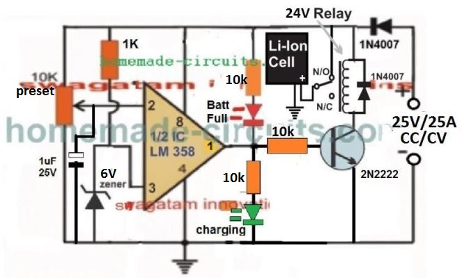
You will need an external constant current constant voltage SMPS rated at 25V/25 amps, then you can use it with an op amp circuit for the cut off as shown below:
Sir what about 12v 14Ah battery then which circuit should be enough ?
Recently during this lockdown, I was trying to explore various ways to develop my own charger for the ebike.
And hence, been surfing a lot on internet where I came across your website which is actually interactive and beautiful.
What I am looking for?
The rated voltage and current capacity are 36V 10.4Ah respectively.
I need to build a charger using some of the best IC with cccv operation and the auto cut-off was thinking if there is a way to charge up to 10-15 batteries simultaneously if possible.
Also te emi filter and PFC would be add on
Could you help me with block diagrams and Ic requirement for the same.
Thanks in advance
You can build the following circuit that will cut off the Li-Ion battery once it is fully charged.
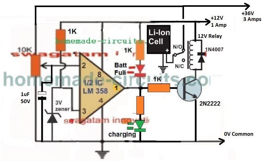
For the supply input you will have to arrange for two SMPS units: 36 V 3 amps or 36V 5 amps, and 12 V 1 amp.
Once you get these, you can power the above op amp circuit and start charging your batts efficiently.
To set up the cut off relay.
Initially keep the 10k preset position toward ground.
Apply the two supply inputs. You will find the relay clicking ON and the Green LED illuminating. Now gradually move the 10k preset upwards, until the relay just clicks OFF and the RED LED lights up. That’s all, the cut off system is all set.
now you can connect the battery across the indicated position and begin charging the batt, which will be cut off once the 36 V point is reached.
PLEASE ADD A 10K RESISTOR IN SERIES WITH THE LINE WHICH CONNECTS 36V WITH THE 10K PRESET, WHICH I FORGOT TO SHOW.
Current will be controlled from the SMPS side, so that won’t be an issue.
Sir, the actual requirement is 42 V input and also I want to charge multiple batteries simultaneously.
Anurag, you can still use the circuit which I suggested in the earlier comment. You will need a 42V, 3 to 5 amp SMPS for the power input source, and you will need a separate 12V for the circuit as indicated in the diagram.
The 42V SMPS will be CC, and CV so no need to worry about that.
Dear Sir
My name is S N Singh ,
I salute your dedication and knowledge of electronics .
I have noticed one great thing with you that you always reply each and every comment, it is a very great thing with you.
It is my first post .I request your goodness to please help me to provide circuit for following
I have a BLDC Ceiling FAN of 12V / 35 to 40 Watt
I want to make a SMPS based circuit to run it from 220V electricity as well as from 12V solar panel of 100Watt . One battery set of 14.8 V Li-Ion 7 Ah to 12 Ah for uninterrupted backup in case of no input.
Solar input is the priority, Load sharing if Solar and Grid if both connected
In case of electricity cut, fan should automatically keep running , but should be off from switch
SMPS Pf >=0.95
Battery charging time should be min 3hrs to max 6 hours
LED Indication extended : Mains ON, Solar Available, Low battery Cutoff, Battery full charge
Protection: Reverse polarity, Short circuit , over voltage, overload
Please share circuit details with components list .
Thanking you very much in advance sir
Thank you Dear SN, I will try to figure it out, but all features may not be available, otherwise the circuit may become too lengthy and due to lack of time it may not be possible for me to design it…nevertheless the end result will be without any issues and serve the purpose well.
Mr. Swagatam, i have made the last circuit above (simplified design) using LM 317 instead of LM338 and i also used 2n2907 instead of TIP 32C. The result was that the formula for Rx wasn’t exact (i used Rx= 1 Ohm and i obtained a current through the battery of 70 mA, a current corresponding to 17 Ohms according the formula). The power supply was 12 V aprox., and when starting charging the 8.4V Ni-Mh accumulator, the voltage across battery leads was different from the voltage on power supply. What’s wrong in my circuit?
Hi Mihai, there will be some difference between the battery terminals and the supply terminals, which can be reduced by reducing the base resistor value of 2N2907. In my experiment the difference was just 0.2V. The battery terminals showed 3.5V, and the supply showed 3.7 V, while the actual input was 5 V.
In your case the 1 Ohm decides the maximum permissible current (1.25 amps), it won’t force the battery to consume 1.25 amps current. The LM317 and the 1 ohm is only to limit the current at the 1.25A level.
The 70mA that you are seeing is what the battery wants, so you can’t force anything above this. The LM317 will only ensure that under no circumstance the input current is able to cross the 1.25 limit.
You can use a relay instead of 2n2907, and then you can except slightly more current to the battery.
I tried to charge my Ni-Mh 8.4 V/280mA accumulator, using the last circuit, with the following results:
-initial Power supply voltage=aprox. 12 V;
-after battery connected, power supply voltage=9v;
-voltage across battery leads=aprox. 5 V;
– current through the baterry= 1 mA;
– The limit current is 28 mA (1/10*280mA, which is the battery charging rating).
I obtained better results with the TIP 142. What’s wrong again in my circuit? Please, help me!
Not sure what’s wrong, because when I tested it worked with minimum difference. The 220 ohm at the PNP base is very low and will be sufficient to switch it fully ON.
Is your ammeter OK? please remove the ammeter and check only with voltmeter.
You can also connect the battery directly with 12V and check the voltage and current reading.
Alternatively You can try a single MOSfeTwith the op amp output and I am sure it will operate much better than BJTs.
By the way Ni-Mh do not require 1/10th current, they can be charged with 50% of Ah rate quite like Li-Ion…in your case it should be 140 mA
In the last circuit, could i substitute the LM338 with LM317 for lower currents? (charging 8.4V Ni-MH accumulators, 280 mAh or higher).
Yes you can do it, since the current is lower than 1 amp for your battery…
Greetings once again Sir.
can a 12Volt solar panel be used as supply for the simplified version above?
Hi Ngang, yes you can use it but you will have to put a LM338 based regulator in the middle, as given here:
https://www.homemade-circuits.com/how-to-build-solar-panel-voltage/
For more efficient charging you can use a buck regulator as explained here
https://www.homemade-circuits.com/5v-pwm-solar-battery-charger-circuit/
Greetings once again Sir.
I successfully completed the garden light. thanks very much for the directives.
i want to find out if I can use the last circuit on this page to charge a lithium ion battery pack i have made. the pack is 2S3P. Giving me 8volt, 7.8Ah.
Or I need a BMS? Also if there is a good circuit for charging such lithium ion packs i will be glad if you send me the link
Thanks
Greetings Ngang, I am glad my articles are helping you!
You can definitely use it for charging 2S3P battery safely.
If you ask this question in forums, many oversmart people will warn you against using it, and it’s due to sheer lack of knowledge.
These guys have made Li-ion cells appear so mysterious and special that it has created an impression all over that Li-ion cell cannot be charged without special chargers. That’s completely wrong.
Li-ion batts can be charged with any charger if two things are maintained correctly:
1) Don’t let it over charge, therefore use an auto cut off at full charge.
2) Don’t let it overheat (above 35 degrees Celsius), so use a current controlled charging.
Both the above features are available in the above mentioned designs, therefore you can go ahead and charge the mentioned battery pack using the last circuit without a BMS.
Just make sure to adjust the Rx value such that the battery temperature remains at around 35 to 40 degrees C.
Begin with 0.5C rate, meaning at current that’s 50% less than the battery Ah rating
Wow.
Thanks very much Sir. This is good news to me because charging Li-ion has really been mystified. I will keep to the above two points.
thanks
You are welcome Ngang, all the best to you!
Hello sir is it possible to use 15v 3A smps with first circuit to charge 12v 9AH li ion battery if it is possible or not please guide me sir thank you
Hello Rabiu, Yes you can it without any issues. After setting up is done you’ll have to connect the battery first and then switch ON the input otherwise the circuit will not initiate the charging process.
Hi,
Can I get a circuit for 20Ah Li-ion battery charger circuit using AC input .
Please suggest .
Hi, you can try the last circuit, which is the easiest one and most efficient. You will have to select an AC to DC adapter as per the voltage spec of the battery, and also set the Rx resistor value accordingly.
sir my mistake only happen i solved
now i rotate preset below 3 v going green led illuminated(because zener diode is there)
above 3 v going red led illuminated so i set 13.2v PIN 2
i put charging battery voltage reach 13.2v above but current not coming 0 (that means cutoff not happen) continios charging
that means pin2 not come below 3v when PIN2 coming below 3v that time only cutoff happen is it right sir?
but in circuit cut off not happen
kindly give suggestion or solution
Cut off will happen when pin#2 voltage goes higher than pin#3 for the last circuit. When cut off happens the green LED must shut off
so red led full charging indication
green led charging indication right?
sir In that video circuit 22k and IN4148 is there but web page circuit not there? why IN 4148 is added any reason?
It is for latching or locking the output to off when the battery is fully charged.
yes that’s right
sir i connected perfectly as per your design
IC’s also changed new one LM324
am using 10k pot 1/2 watt using RX resister set 1.2ohm is this ok sir?
then leftside 10k pot i set 13.2v then i put charge. volatge going above 13.2 v but current not cut off is continous charging
LM324 IC’S pin2 showing 13.2v is correct?
Pin3 showing 14v is correct?
LM324 output showing 11v is correct?
both led’s illumainted why?
kindly give solution
board almost ready
Manoj, if you connect it properly then it has to work.
The pin which is connected to zener diode will show the zener voltage value and not any other voltage.
You must use a preset and not a pot to set the cut off level.
Don’t bother about the current, first set the cut off voltage correctly, current can be measured once cut off voltage is properly set and confirmed.
both leds will never illuminate together, I hope you have connected one led in series with the transistor base.
sir i have 11.1v 1AH li-ion battery..i need charging circuit..i need auto cutoff feature when battery getting full charge kindly give solution
sir am confused..I make that at first time you sent USB circuit that circuit charging time red led full charging green led comes is it right?
pleas read the set up explanation here
https://www.homemade-circuits.com/usb-automatic-li-ion-battery-charger/
i taken 10k 1watt Pot shorted 2pins connected to ic 2 and 10k another end..another pot pin ground
That green led connection you said new way in 6v 4a circuit why sir? Any corrections is there USB circuit?
The LED at the transistor base prevents any leakage voltage from the opamp to reach the transistor base and guarantees genuine switching of the transistors.
10k preset center pin will go to pin#2 of the IC, the other two outer pins of the preset will go to the +/- supply lines. I have explained the setting-up in the articles, please read them to understand the procedure.
Hi Manoj, since your battery is not a high current one, you can try the following design instead of the above explained design:
https://www.homemade-circuits.com/usb-automatic-li-ion-battery-charger/
you can feed 13.2V from left side and adjust the preset such that green led just shuts off and red led comes ON….your circuit is set now!
after setting up, connect the battery first and then switch ON power from left side with 14V input
Thank you sir
so input voltage is 14v right? how much current will going when put charging?
i can’t understand for feed 13.2 v adjust the preset so describe clearly sir.
when li-ion battery reaching 11.1v 1000mah autocutoff need and also can i use LM358 or LM 321?
Hi manoj, full charge level of 11.1V li-ion battery will be 12.6V but since the input diode of the circuit will drop 0.6V therefore we take 12.6 + 0.6 = 13.2V as the cut off threshold. Once you fix this using the preset, your battery charging will be cut off at this level each time.
Even with 14V as the input the cut will happen at 13.2 meaning at 12.6V for the battery.
If your input current is fixed 500mA then no need of the current control stage using the BC547 transistor and its base resistor.
But if your input current is higher then you will have to include the indicated BC547 stage and dimension the shown Rx resistor accordingly.
How can I fix 500 mAh current?
sir i’m connected as per USB circuit now charging properly but both led’s illuminated ..when i on power that time both led’s illuminated then i preset volatge 13.2v that time also both led’s blowing
Then certainly you have done something wrong in your circuit, which I cannot troubleshoot from here. Or your IC may be faulty
now current going increase only…but battery 2pin RMC getting 13v when i on current and voltage going increase
connect battery first and then switch ON input power, and for proper response please remove the green LED and connect it in this way
https://www.homemade-circuits.com/make-6v-4ah-automatic-battery-charger/
yes i set 13.2v i connect led also red led blowing
Sir i cannot charge the battery when i switch on power at the same time current also increasing voltage also increasing but concept current will act high to low at the same time voltage low to high..so kindly explain that
Once you fix this using the preset, your battery charging will be cut off at this level each time.i cannot understand how it will be cut off at this level? how will sense voltage and current?
another doubt sir why use zener diode?
kindly explain above all things then only i will clear
Hi Manoj, I have already explained you everything, please tell me how did you set the preset?
did you feed 13.2V at the input, did you connect the LEDs?
sir i have one doubt. can i use 3.3v zener diode 1/4 watt and can i use LM324?
yes you can use them….
sir can i use 3.3v zener diode?
kindly explain why use zener diode that area?
you can use any zener between 3 and 6V, it is for fixing a reference value at pin3, when this value is exceeded at pin#2, pin#6 becomes zero (cut off).
sir all resistors 1 watts right?
Except Rx all are 1/4 watt
Now I almost make circuit thank you sir battery positive connect to IN4007 cathode..battery negative connect to IRF540 collector right?
yes that’s correct, wish you all the best!
Now I’m cleared you told LM358 one amp used another unused so can I use LM 321 ?
all opamps basically work in the same way, so no problems you can use anyone of them.
Use Rx = 0.6 / 0.5 = 1.2 ohms 1 watt
Thank you valuable reply sir but TIp 142 prize very high..I make project below 100 RS for simple li ion charging circuit kindly give suggestions
sorry you won’t need TIP142 here, you can use TIP122 or a mosfet IRF540, or a TIP31C, or 2N2222
Sir pls i want to charge 7.4v 8ah lithium ion battery
sir thanks for your assistance but pls help me my 741 is heating.thanks
How much voltage have you used at pin#7 of 741, make sure it’s not over 15V
I use 12v as input sir
at 12v 741 will never become hot, there could be some other fault in the connection, or the IC itself could be faulty, so please check everything accordingly.
Sir i check,there is no error,please if you can enlighting me why pin7 is going to ground and pin4 to ground.thank i appreciete your site
Hi Marcus, I am very sorry, the diagram is showing wrong supply polarity across the IC pins of 741…pin#7 should go to the positive, and pin#4 to the negative line. I think your IC might have already burnt, so please use a new IC and change the supply pins accordingly.
I’ll write a warning message under the diagram immediately.
Marcus, you can use the last circuit for your need, use 8.4V, 5 amp or lower as the input
Thank you sir,can i use 12v 5amp as my input to charge 7.4v 8ah ?
The input should be 8.4V strictly, do not use 12V
Sir,I want to simulate the above circuit..Can u please tell me which simulation software i can use for simulation???
Hi S.Sharma, sorry I never use simulator so I can’t suggest about them, you can build them practically and verify…all will work with 100% perfection.
Thanks a million! Please IF need circuit diagram of 24volts 12amps charger circuits.
You are doing a great job.
sir I want to controll 14.8v li poly battery charging, is the above given circuit is tested?Is this circuit will be suitable to use for 4s li_poly/li-ion battery for 14.8v? if yes pls reply as soon as possible?
Anil, the above circuit is tested, but it will not charge the cells separately, rather the entire series module together, end to end
Hello Mr. Swagatam
I would like to use the above design to charge a 36 v dc 17 AH Lithium battery for an electric bike application.
The source is 120 v AC step down to 40 v dc after the full wave bridge rectifier and (1/5 of 17A) 3.4A of secondary supply current capacity. What design change do I need to do to make it work for a 40 v dc supply? I assume the parts above will work as it is. My concern is the supply voltage for LM321 and LM338. Could I use a zener diode instead to drop the supply voltage of 321 to 24v and 338 to 32v? No rush to reply. Great website and enthusiasm for all electronics hobbyist. Thank you for sharing your time and talent. Dean – Vancouver BC Canada
Thank you Dean, I am glad you liked my site.
A 36V battery will require 42V to get charged fully, while the maximum permissible input to a LM338 IC is lower than 40V, therefore the LM338 section cannot be used for charging your battery.
You can perhaps try the second last design from the following link and customize it for your purpose:
https://www.homemade-circuits.com/how-to-make-versatile-variable-voltage/
You can eliminate the Q4, R2, D1 stage, as it may not be necessary.
R5 may be calculated as follows:
R5 = 0.7 / safe charging current
This resistor could be replaced with a link and the Q5 stage eliminated if the input supply from the transformer is selected to be around 3 to 5 amps.
The battery may then be directly charged from the output of the above circuit, however it must be ensured that the output is precisely set at 41V, that’s 1V less than the actual full charge level, this will prevent the battery from getting fully charged to the edge, and an extra auto cut-off circuit could be avoided.
Hello sir,
I need to build up 12 v 8800 mah li ion 3s4p charger with protection circuit.I have a supply of 12 v 2amp of smps circuit can i use it?And i also need a circuit which automatically switch to this battery supply when there is no ac power.I have used 12 v 2amp smps . So how can i make circuit for charging a 12 v 8800mah li ion 3s4p battery using this smps supply with protection circuit and auto switch to battery mode incase of power outage with path isolation of ac mains and battery supply path.
Sunny, yes you can use the above circuit for your application,, but a 12V supply will not charge a 12V battery, change it to a 14V supply input.
for changeover you can simply use a relay with the input supply and wire the battery positive with N/C, input supply with N/O and pole with the load….negative line can be common with the battery, input supply and the load
Thank you sir for your valuable reply. But sir where do i connect relay circuit for switchover and charging circuit after smps circuit ? How can i increase smps output voltage from 12v to 14v with same 2 amp rating.I am confusing about relay connection so please sir guide me about this. And I have used nema 17 motor 200 steps/revo. Ao what will be the maximum current it will draw at very low speed. Battery selection will be depends on this current. I have chosen 12v 8800mah li ion battery. This battery can give longer backup capacity? (aprox. 6 hr.)
Sunny, You can connect the relay coil with the SMPS output. and connect the contacts as explained in the previous comment.
if your SMPS has a preset facility to tweak the voltage then you can use it, otherwise you may have to open the SMPS and do some serious modifications as explained in the following article:
https://www.homemade-circuits.com/2015/04/how-to-make-variable-smps-driver-circuit.html
sorry I cannot suggest about the current consumption of the motor, you will have to find it from the motor’s technical specs
Hi, I really dont understand D2 D4 & D5 purposes
and in the second diagram, the two added 4148 ???
everytime I see a diagram I feel like I dont understand anything, and I have been doing electronics for years now 🙂
Hi, D2 makes sure that R3 does not form a potential divider with the preset as long as the output of the opamp is 0V, and this D2/R3 loop only becomes relevant and active when the opamp output becomes positive, and lathes the pin3 of the IC permanently.
D4 helps to block any leaking offset voltage from the opamp output and prevents false triggering of BC547
D5 cuts down the 5V to 4.3V which looks more suitable for charging a 3.7V Li-Ion cell.
the two 1N4148 in the second design are for isolating the Rx voltage from the opamp output voltage.
Hello sir.
I want to build a 9volt-30ma ni-mh battery charger with auto cut off(stop charging when the battery gets to its full charge). But I don't want to use integrated ics. I want to build a reliable, cheap circuit that just uses opamps and other simple things like transistors and cte. I want to have a circuit like what you explain in this page for a li-ion battery charger.
Thanks. Please help me sir.
Hello,
You can try the following circuit for your requirement
https://www.homemade-circuits.com/2016/05/how-to-set-ic741-battery-charger.html
Hello sir, I can't understand the last picture Rx explanation (Rx=1.4/current limit (amps)). If I want to limit my current at 1 ampers or 1000ma, I need a 1.4 ohm resistor?
how can I choose the suitable resistor in Watt? (I mean 1/4W,1W or higher?)
another question is that setting up the last picture circuit is the same as what you explain for earlier circuit?
Please help me.
Thanks
Hello, yes the pot setting up procedure will be identical to the first circuit.
the Rx wattage can be calculated as follows:
watt = 1.4V x 1amp = 1.4 watts
Respected Sir, Happy NEW YEAR.I am Rajesh GS.Working as an service/repair technition.I need a help from you.I want to build a charger for Li-ion V-Lock Fxlion BP2000 14.8v/9AH/130Wh .It need 16.8v/2Amp chrger(as per their charger catalog)I saw your great idea "high current li ion chrger' circuit.Is this circuit good for it,or need any change in parts/circuit.I think li ion battery need cv,cc,to charge?so can i add your another CV,CC (using LM338)circuit before this circuit?Please help me withyour great advice ASAP.Thank you very much…
Rajesh, initially you mentioned that your battery was Li-ion but now you are specifying it as SLA….for 9SH SLA battery 3.6amp will be quite high but not for Li-ion…so please specify the correct one that you are using.
any opamp circuit will produce extremely sharp cut-offs so even the above circuit will do the same undoubtedly, if you have not understood the concept then I am afraid you'll continue having problems with this designs.
for compensating the 0.7V drop you can make the LM338 output at 15V.
You can study the following article for more info:
https://www.homemade-circuits.com/2015/07/designing-customized-battery-charger_26.html
Thank you very much sir for your replay.I am planning to use 19v/3.6amp Laptop adaptor as power supply.(is it OK ?)so i asked to add CC.CV circuit.Sir i built this chrger,but it is not cutt off sharpily(i think,that is lack of my understanding this circuit/set up).I tested with a 12v/9Ah SLA battery and LM741.Is it ok?. I have one doubt also,D5 6A4 diode have its on voltage drop(.7v) is it affect the sharp cuttoff/output volts?Sir can you please explain detailed set up procedure simply again for me.(I know you are a very busy man)Once again thank you…
Happy new year to you too Rajesh!
You can definitely use the above concept but make sure you understand the building and the set up procedures correctly and implement them correctly.
If your transformer or the input power source is rated at 2amp for the mentioned 9AH Li-ion battery then I think you won't need to add anything before the shown circuit, you can use it as given above.
Hi,
is it recommend just for 1 Li-Ion battery or also possible for 4 ?
With kind regards,
Thorsten
How many amperes does the circuit output?
5 amps maximum
Hi,
yes it can be used for one Li-ion preferably which are rated with higher AH, but not for 4, because Li-ion batteries are not recommended to be charged in parallel or in series unless the charger is specially designed to handle this
thankyou
in this circuit have over discharge cut off?
yes it has….
respective sir happy diwali
to day i read High Current Li-ion Charger Circuit from your site can this circuit protect battery from over charge or over discahare? pl tel me because low battery cut -off and overload protection circuit not work in bike my 6 li-ion battery is shot for this circuit
thankyou
Happy Diwali to you too Shuddhatam,
yes the circuit is equipped with an automatic over charge control and cut off
But, you must know all the basics of electronics and should be able to implement the circuit correctly as explained in the article, otherwise you may not be successful with the results
Hi pls let me know what is the value & number of T1
T1 is BC547 transistor
How it can sense the battery and switch the flasher circuit to charger circuit when battery is connected?
I explained the sensing procedure of opamps it in the following article, if you remember
https://www.homemade-circuits.com/2015/03/battery-charging-fault-indicator-circuit.html
I just need a battery sensing switching circuit.All other i have.
you can try the second circuit from the following article:
https://www.homemade-circuits.com/2011/12/how-to-make-simple-low-battery-voltage.html
Waiting for the reply.
I have finalize all circuitry just need this scenario to be fulfilled:
I want slow flashing =Standby mode
Fast flashing= When charging (When battery connected)
Solid = Fully charged.
the circuit will become complex and elaborate with 3 opamps, and many transistors.
Hello regarding this circuit.
Can it be modified for 4.2V,1200mAH while charging current should be 0.5A.In place of LM338 LM317 can be used? and in place of Lm741 can we use LM358 or Lm393?
And if i put a LED flasher in this circuit when in standby and it will go off when battery is connected how that be possible?.(i have flasher circuit just need connection)
yes you can use it for the required purpose with LM317 IC
i could not understand the operational details of your flasher, pls explain again properly.
alternatively you may also try connecting the last circuit from the following link with the battery terminals:
https://www.homemade-circuits.com/2014/06/flashing-led-battery-status-indicator.html
https://www.homemade-circuits.com/2014/06/flashing-led-battery-status-indicator.html