In this post I have explained a high current Li-Ion battery charger circuit which can be used for charging any high current, such as 2S3P, 3S2P battery packs. It can be also used for charging other similar high Ah rated Li-ion battery from a car or a truck battery. The idea was requested by Mr. Neil
Charging a 8800 mAh Li-Ion Pack
This is perhaps very cheeky of me to ask for your help, but my design skills are limited in electronics and as a volunteer my budget is limited.
I am a volunteer for a local Search and Rescue organisation (Suffolk Lowland Search and Rescue), we are on call 24hrs a day 365 days a year, our work involves finding anyone who has gone missing in Suffolk (and bordering county’s).
Search often take place during the hours of darkness and we have a particular need for good torches, which need to be ready for action at a moments notice.
I am part of the mountain bike rescue team, we cover ground very quickly and can search paths much faster then foot teams, lights are again very important and I hope this is where you can help.
I have recently bought a Cree LED light for my bike, it is powered by a 8.4v Li-ion 8800mAh battery pack, I have 2.
These units came with a mains powered charger (240v UK) and what I would like is to be able to charge them in the car where the bike is kept.
I noticed you have already designed some charging circuits for this type of battery and I wonder if you could modify your design to be able to charge from a 12v car circuit to these specification batteries.
The car circuit will be switched with the ignition. I am very capable of constructing the circuit, it’s just my design skills that are limited!
I very much appreciate anytime you spend on this, it will help not only me, but potentially any lost sole in Suffolk.
Kindest regards,
Neil.
Simplest Solid-State Design Using an Op-Amp (Recommended)
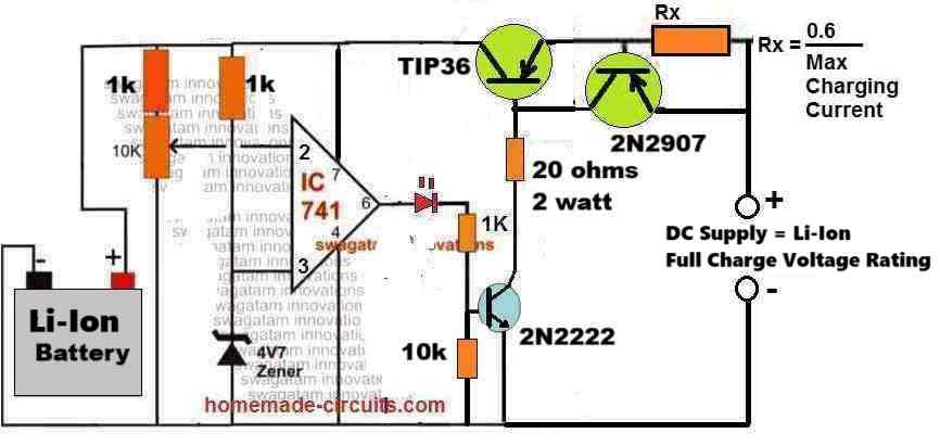
The following circuit of a high current Li-Ion battery charger circuit can be efficiently used for charging all types of Li-Ion and Li-Po batteries, safely. Because this design, despite being simple, includes a constant current feature and also an automatic cut-off feature.
How it Works
Initial Charging Phase:
When the battery is connected and its voltage is below the full-charge level, the IC741 comparators output is high.
This activates the TIP36 allowing current to flow into the battery through Rx.
The charging current is controlled by Rx to prevent overheating or damage to the battery.
Current Limitation:
The value of Rx determines the maximum current delivered to the battery. This prevents overcurrent and ensures safe charging.
Voltage Monitoring:
As the battery voltage rises and approaches the full charge threshold then the non-inverting input (pin 3) of the IC741 exceeds the reference voltage at the inverting input (pin 2).
This causes the IC741 output to switch low turning off TIP36 and stopping the charging process.
Automatic Cutoff:
When the charging stops, the battery is protected from overcharging. The circuit automatically resumes charging if the battery voltage drops below the threshold.
Calculations for the Design
Selection of Rx (Current Control Resistor):
The resistor Rx limits the charging current Imax as per the formula:
Rx = 0.6 / Imax
For example:
If Imax = 1A:
Rx = 0.6 / 1 = 0.6 Ohms
Ensure the power rating of Rx is sufficient to handle the current:
P = Imax2 * Rx
For Imax = 1A and Rx = 0.6 Ohms:
P = 12 * 0.6 = 0.6 W
Use a resistor with a power rating slightly higher than the calculated value (e.g 1W or 2W).
TIP36 Base Resistor
The base resistor ensures sufficient base current for TIP36:
Ibase = Ic / hFE
Where:
- Ibase = Base current
- Ic = Collector current (equal to Imax)
- hFE = Current gain of TIP36 (typically it is around 30)
For example, lets say if the required collector current Imax = 3A:
Then base current Ibase = 3 / 30 = 0.1 A (100mA)
Then we can calculate the base resistor value as:
Rb = (Vout - Vbe) / Ibase
Where:
- Vout = Output voltage of IC741 (approx. 11V)
- Vbe = Base-emitter voltage of TIP36 (approx. 0.7V)
Rb = (11 - 0.7) / 0.1
Rb = 10.3 / 0.1
Rb = 103 Ohms
How to Setup the above Design
First make sure the wiper of the 10K preset resistor is pointing down towards the ground. After that, you need to add a sample voltage from the BATTERY SIDE.
It's really important that this voltage comes from the battery side and not the transistor side. But remember don’t connect an actual battery while you’re testing.
The sample voltage should be a little higher than what the battery's full charge level is. When you do this you should see the LED light up really bright.
Then slowly turn the 10K preset until the LED goes out completely. Once that’s done you can disconnect the power supply and hook up a dead battery. You’ll see the red LED turn on.
Next connect the right amount of full charge voltage from the transistor side to start charging the battery.
When the battery hits the set cut-off point for charging, the red LED will turn off which means the battery is fully charged, and is cut-off from the charging supply.
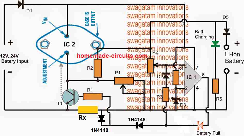
Using LM338 with Op-Amp
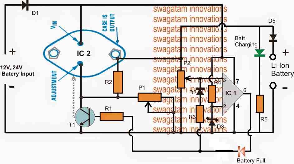
The shown high current Li-Ion battery charger circuit is featured to charge any Li-ion battery upto 5 AH with the shown IC2, or for 10AH batteries if IC2 is appropriately replaced with a LM396
The LM338 IC2 is a versatile voltage regulator IC which can be specifically configured for charging Li-Ion cells with the essential features such constant current and constant voltage.
The above design is configured as a constant voltage Li-ion charger, since we assume that the input supply to be a constant current.
However in case the input supply is not current limited, the IC2 can be enhanced with an effective constant current feature. We will discuss this at the end of this explanation.
The design consists of two fundamental stages, the IC2 voltage regulator stage and the IC1 over charge cut-off stage.
IC2 is configured in its standard voltage regulator form, where P1 functions as the control knob and can be adjusted to generate the required charging voltage across the connected Li-ion battery at the output.
IC1 pin3 is the sensing input of the IC and is terminated with a preset P2 for facilitating the over charge voltage level adjustment.
The preset P2 is adjusted such that when the battery reaches its full charge value, the voltage at pin3 just becomes higher than pin2, resulting in an instant high at pin6 of the IC.
Once this happens the high from pin6 latches on to pin3 with a permanent high via R3, D2, freezing the circuit in that position. Remember this latching network is optional, you can remove it if you wish, but then the the Li-ion battery will not be permanently cut-off, rather intermittently switch ON/OFF depending on the full charge level threshold of the battery.
The above high is also delivered at the base of the BC547 which immediately grounds the ADJ pin of IC2 forcing it to shut down its output voltage thereby cutting off the voltage to the Li-ion battery.
The Red LED now illuminates indicating the full charge level and the cut off conditions of the circuit..
Circuit Diagram
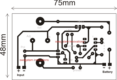
PCB Design
Parts List fro the proposed high current 12V/24V li-ion battery charger circuit
- R1, R5 = 4K7
- R2 = 240 Ohms
- P1, P2 = 10 K Presets
- R3, R4 = 10K
- D1, D5 = 6A4 diode
- D2 = 1N4148
- D3, D4 = 4.7Vzener diode 1/2 watt
- IC1 = 741 opamp for 12V input, LM321 for 24V input
- IC2 = LM338
How to Set up the circuit.
- Initially do not connect any battery at the output, and rotate P2 so that its slider touches the ground end, in other words adjust P2 to make pin3 to zero or ground level.
- Feed the input voltage, adjust P1 for getting the required level of voltage across the output where the battery is supposed to be connected, the green LED will be lit up in this position.
- Now very carefully move P2 upwards until the the red LED just illuminates and latches in that position, stop moving P2 any further, confirm with green LED shutting of in response to red LED illumination.
- The circuit is set now for the required high current Li-ion charging from a car battery or any 12/24V source..
Adding a Constant Current Feature in the above Design
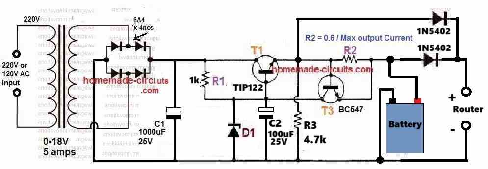
As shown below, the above design can be further improved by adding a current control feature, which makes the proposed high current Li-ion charger circuit perfect with the features of CC, and CV, that is with constant voltage and constant current attributes.
Note: The latching of the op amp is not compulsory, hence the D2 and R3 can be removed, and the circuit will still work nicely and automatically cut-off when the battery is fully charged.
Simplified Design
While the above explained circuits are great with their features and working, the use of LM338 makes the design a bit complex, and costly.
A little tinkering reveals that the application could rather be implemented using only a single opamp and a BJT based current control as shown below:
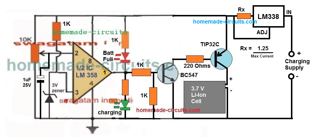
A 1uF capacitor is introduced at the inverting input of the IC, which ensures that the IC always starts with its output at positive high when powered. This in turn allows a guaranteed switch ON of the output transistor, and enables the connected battery to lock in with the charging process.
The concept has been tested thoroughly, the video proof can be seen here.
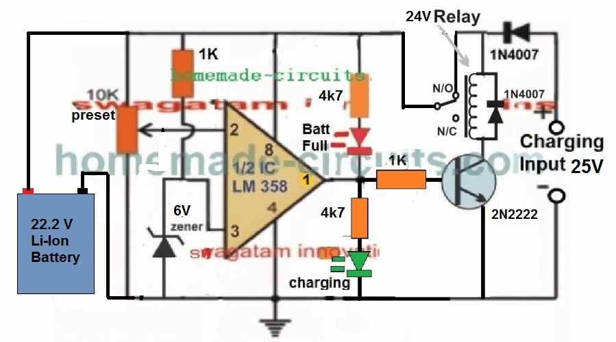
22.2 V Li-Ion Battery Charger Circuit
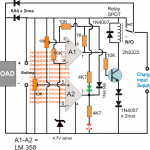
The following diagram shows a simple yet very accurate Li-Ion battery charger circuit with cut off. This charger can be used for charging a 6S Li-Ion battery rated at 22.2V.
WARNING: IN ALL THE ABOVE CONCEPTS, TEMPERATURE REGULATION FOR THE BATTERY IS NOT INCLUDED, SO PLEASE MAKE SURE TO ADJUST THE CURRENT TO A LEVEL WHICH DOES NOT CAUSE THE BATTERY TEMPERATURE TO REACH ABOVE 40 DEGREES CELSIUS.
How it Works
Let's assume there's no battery connected at the left side of the above circuit, and a charging input is switched ON from the right side of the circuit as indicated in the diagram.
In this situation, we find that since the initial relay position is on the blank N/C point of the relay, so the circuit cannot get powered, and so nothing happens to the circuit, and the circuit stays unresponsive and dormant.
Now, if a discharged battery is connected on the left side of the circuit as shown, the opamp gets powered through the battery voltage and its input pin#2 detects the discharged state of the battery voltage, which could be lower than the pin#3 reference of the IC, as per the setting of the preset.
So this instantly causes the output pin#1 to go high (because pin#3 potential is higher than pin#2 of the IC).
The high from pin#1 turns ON the transistor and the relay, causing the relay contacts to move from the default N/C points to the N/O points.
So now the charging supply is able to quickly get connected with the battery through the N/O contacts and the battery starts charging. In this situation, the input charging voltage is dragged down to the discharged level of the battery....and the battery now slowly begins charging.
As soon as the battery gets charged to its full charge level, the pin#2 potential now becomes higher than the pin#3 reference of the opamp, which immediately causes the output pn#1 voltage to become 0V, turning off the transistor and the relay.
The relay contacts now return back from the N/O point, to its default N/C point, cutting off the charging supply to the battery...
How to Setup
Initially, keep the preset fully rotated towards the ground side.
Connect a diode between the relay coil and the opamp positive rail as given in the following diagram:
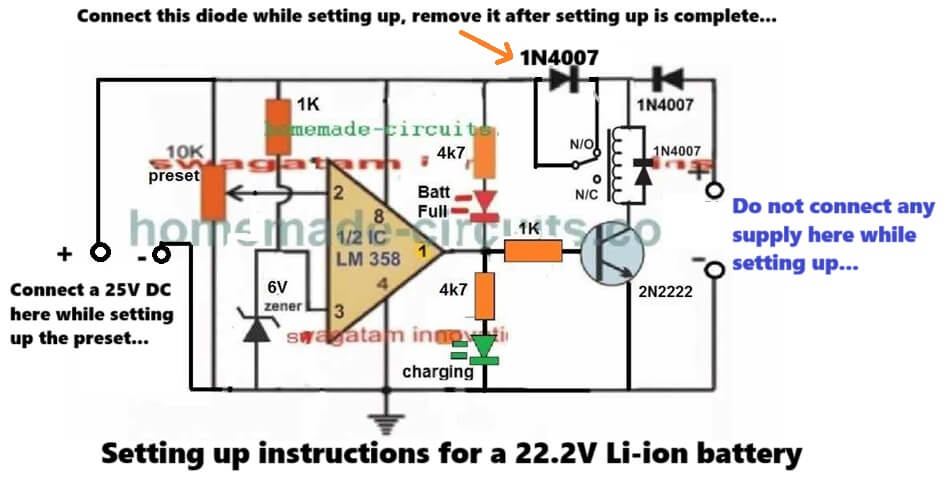
Now, connect a suitable input charging supply around 25V on the right side of the circuit.
So now 25V gets applied to the circuit. And you will see the relay clicking ON, and the green LED switching ON.
Now, slowly adjust the preset until the relay turns OFF, and the green LED shuts off, causing the red LED to turn ON.
That's it, your circuit is fully set now for charging any high current 22.2V Li-ion battery or any other battery rated between 3.7V and 29.6V Li-ion battery. Seal of the preset with any suitable glue....
Next, you can remove the power supply from battery side and connect it at the right side which is input charging side of the circuit.
Finally, connect any discharged battery from the left side of the circuit, as indicated in the diagram, and start charging the battery with high current, and an automatic full charge cut off..


Questions & Answers
hello
in the first circuit when the battery is discharged, tip36 is on and thr Rb (20 ohm) is concuming the power of battery. is that right?
Hi, No… 20 ohm is getting supply from the input charger DC supply, through the emitter pin of TIP36. This resistor must be calculated based on the Ah rating of the battery.
Thank you for previously publishing the current voltage current adjustable circuits of the LM 337-338-350 integrated circuits. Could you publish the same circuits in LM337, thank you.
Thank you Mehmet,
You can find a few designs using LM337 in the following article:
https://www.homemade-circuits.com/how-ic-lm337-works-datasheet-application-circuits/
Hi brother, in 22.2 v lithium battery charging circuit ,the diode which connected between input volts 25v
is it is connected to the N/O pin or N/C
pin , because in picture its connected N/C but it is written N/O (normal open)
Hey Bro, The input supply diode is connected with one terminal of the relay coil, and the N/O contact.
hi, I assembled this circuit both LEDs on/off while adjusting the pot 10k, showing charge start and stop
but here some time missed relay on/off , though proper output from ic pin1 to 1 k for transistor base
but unable to operate relay
Hi, It is because the relay coil is not getting any supply. Please make sure to keep the preset initially to the ground level, next connect a 25V input charging supply from the right side end, and proceed as per the following diagram:

Thanks, dear 🙏 , yes I checked the circuit , relay will energized only on charger connection , because no +ve for it it connected to batteries.
thanks bro
Prefect Bro! Glad you could figure out the issue….let me know if you face any further issues with the circuit…
Hi, in the updated 22.2 v battery charging circuit you have mentioned IC pin#6 as output , i think it will be pin#1 in the said circuits , Thanks
Thank you for pointing out the mistake!! Yes, for this LM358 IC it should be pin#1, I mistakenly assumed it to be the IC 741 whose output pin is pin#6.
I have corrected it now…
Good afternoon Mr. Swagatam,
I’m fairly new to PCB design (6 months).
Do you think this circuit will work for a BB2557/U, 99 Wh 6.8 Ah, Rechargeable Lithium-Ion Battery? Nominal Voltage is 14.4V for one cell and 28.8V for both cells. Attached is a link to the battery I am trying to charge.
I’d also like to be able to use the battery to power things when it is not charging.
Please let me know your thoughts and any tips you may have for this battery.
Thank you.
Hi Aaron,
You can charge all Li-ion and Lipo batteries using the above circuits safely, by appropriately adjusting the current limit.
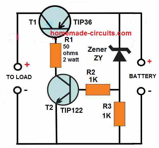
To be able to operate a load simultaneously, you can use the following design:
Make sure to select a zener diode such that the output across the battery points is slightly lower than the full charge voltage specification of the battery.
Fix this without connecting any battery.
For example if the battery full charge voltage spec is 12.6V, then adjust the zener value to get around 12.4V across the battery points (without battery connected).
R2 must be fixed as per the given formula.
R2 = 0.6 / Max permissible current
For a Li-ion battery the max permissible current can be around 50% of its Ah value.
Thank you so much! I’ll build this and run some simulations.
You are most welcome!
The simulations turned out great.
One more question for you. You said this will charge and operate the load simultaneously. Does this mean the battery is not providing the power to the circuit? I’m trying to have the battery as a backup in case power to the system is disrupted. That way the battery will kick on and provide the power needed to operate until depleted or until power from the original circuit is restored.
Thanks for the update.
The load will always keep getting the operating power from the input mains. If the input mains is removed or fails then the load will start getting the power from the battery.
Thank you for clearing that up for me.
Glad I could help!
Dear Mr.Swagatam,
I am viswanathan from India reg. my Milagrow Floor cleaner using 14.8 v lithium battery. Now it is not working. I am based Electronics. Aged 77 yrs. No person is repairing the Milagrow machine in Chennai. Would you please forward the working diagram of Power supply and your valuable suggestion to rectify the defect in the Milagrow Floor Cleaner machine.Thanks in advance.
Viswanathan SA
Thank you Viswanathan S.A, for your question,
Are you looking for a Li-ion battery charger circuit for a 14.8 V Li-ion battery, if yes, then I can certainly help you with a proper working circuit diagram. In that case i will also require the Ah value of the battery.
Please let me know your thoughts on this….
Please what is the safe charging voltage for 11.1v lithium set, full battery cut off and low battery cut off voltage. Thanks
The safe full charge level is 12.3V which will not require an auto-cut off. If you have an auto cut off facility then use 12.6V.
Low battery limit is 9V.
Please will the 12.3v be the charging voltage or what level?
It is the charging voltage that must be fixed and never exceeded.
Thanks Swagatam, please advise, how to safely charge without a BMS. Is it advisable and possible.
It’s definitely possible to charge any battery optimally and safely without a BMS.
In your case keep the full charge level “fixed” at 12.3V, and use a current level that’s 50% less than the mAh rating of the battery.
Please, I have 2 different sets of lithium batteries, a set charges battery faster and retains better, the other charges too slow but retains not as good. Why is it so, sir?
Hi Daniel, without checking the schematics of the two chargers it can be difficult for me to figure out the difference in their working specifications. So if possible please the schematic details of the two chargers.
I meant charging the 2 new sets of lithium batteries with a transformer based charger, the outcome was significantly different
You can try connecting an ammeter in series with both the batteries and monitor how much current each of the batteries consume while charging, this will instantly show you the difference between the two battery conditions.
Yes, thanks for this guide, the better battery
set draws 500mA while the other battery draws 1.8Amps but poor outcome. I don’t understand this
I got the 3-5A charging current but why at the rate I used above , the battery sets behaved differently with different responses.
The amount of current the battery consumes will entirely depend on the specific battery, we cannot force the battery to consume the amount of current as we desire.
Can you please tell me the Ah rating of the batteries?
12ah new lithium battery set
A 12 Ah Li-Ion battery will require around 4 to 10 amp current, to charge effectively.
Please try increasing the supply current to at least 3 or 5 amps and check the results.
For C10 / 150ah lead acid battery ; max current is 150/10=15amp
But for 3C / 150ah Lithium battery ; max current is 3X150=450amp
There is division but here is multiplication.
Am I Correct?
Please use this formula to calculate the C rate:
C rate = current / battery capacity
bat CAP is 100ah.
max current=3C=?
Max current=0.5C=?
Max current cannot be 3C.
0.5C = 50 Ah
which company mppt is best for 1kw 24v panel and using lithium battery 24v 50ah 1c.
Sorry, I have no idea regarding which MPPT company is the best…
I have 7S 18650 50ah lithium battery.
which solar mppt will be best suitable for this.
some mppt are for 6s also.
What is the voltage range for 7s.
I am confusing for 6s vs 7s.
no one mentions if mppt is for 6s or 7s.
hope you fine
7s = 7 x 3.7 = 25.9V and its full charge level would be 7 x 4.2 = 29.4V, or simply 29V. With reference to these specifications you can select which MPPT is suitable.
I have two lithium bat of 24v 50ah with bms.
can I connect in parallel?
hope you fine!
You you can connect them in parallel.