In this post I have explained how to make a LED string light which can be operated from 220V mains through a single inexpensive PPC capacitor. The idea was requested by Mr. Basit Momin.
WE STRICTLY CAUTION YOU THAT YOU BUILD THIS CIRCUIT ONLY IF YOU ARE AWARE OF THE DANGERS OF MAINS AC AND KNOW HOW TO MAINTAIN EXTREME SAFETY AGAINST IT.
REMEMBER, THE CIRCUITS EXPLAINED BELOW IS NOT ISOLATED FROM MAINS AC AND CAN INFLICT LETHAL ELECTRIC SHOCK IF ANY EXPOSED PORTION OF THE CIRCUIT IS TOUCHED IN POWERED CONDITION, SO MAKE SURE THAT THE FINAL STRING LIGHT ASSEMBLY IS PERFECTLY INSULATED WITH PROPER PLASTIC COVERS AND CAPS.
Technical Specifications
I am trying to make AC 1 watt led bulb like 6.2 v 3 amp miniature lamp or festival decoration lamp so it will be easy to solder led without seeing plus and minus of leds , so it will be easy to solder led in series without seeing plus and minus of led so pleas help
Actually I want to make 100 nos of led toran of 2 array each array of 50 leds I am trying to convert leds in AC bulbs like 6.2 v festival decoration lamps so that's my question sir
Can we run the LEDs without the circuit by adding some ics to each led. I want to run it direct on 230v AC without any circuit like festival series lamps.
Basit Momin
Analyzing the Circuit Request
Hello Basit,
LEDs are different from filament bulbs and are much vulnerable to current fluctuations, without a dropping capacitor the LEDs will start blowing off with the slightest voltage fluctuations if connected directly or through resistors.
Therefore a recommended capacitive power supply circuit has to be used with it.
Basit: So we cannot make AC led Series bulbs ?
Solving the Circuit Issue
You'll have to include the high voltage isolating capacitor, rest of the components can be eliminated.
make two 50 LED series and connect their opposite ends together, meaning the anode end of one series should be connected with the cathode end of the other series in both the ends.
Now simply connect one end of this assembly to one of the mains terminals while the other to the other mains terminal through a high voltage capacitor.
The whole set up will be too dangerous to touch, exercise adequate caution.
The Circuit Diagrams
Testing the above LED string light design using a single PPC capacitor:
The idea looks simple and feasible and also quite reliable due to the large number of LEDs in series taking care of the initial surge current.
The large number of LEDs makes sure that the total LED forward drop is close to the AC mains value which enables restricting the initial current to a reasonable level.
If we assume the forward drop of the shown white LEDs to be around 3.3V, then with 50 LEDs in series it gets to approximately 3.3 x 50 = 165V, though not too close to 220V but sufficient enough to just counter the initial surge from the PPC capacitor which acts like a momentary short circuit each time power is switched ON.
Probably 90 numbers would be just adequate and perfectly safe.
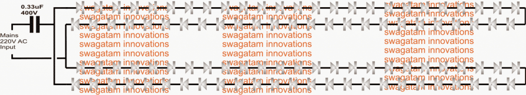
As can be seen in the above diagram, there are 50 LEDs on the upper string joined in series and an identical string with an identical number of LEDs at the lower side of the design.
The free ends of these two series are connected to each other but using the opposite polarities, that is the anode side of one string is made common with the cathode side of the other string and vice versa.
The mains AC is applied to these common joints through a PPC high voltage capacitor.
A nominal 0.33uF is shown in the diagram assuming that 5mm LEDs are used in the circuit.
We know that mains AC is fundamentally composed of alternating current which changes its cycle polarity 50 times a second, constituting the 50 Hz spec.
The LED strings are deliberately connected with their opposite end polarity so that one string illuminates in response of one half AC cycle while the other string for the other opposite AC half cycle.
Since this is supposed to happens very quickly (50 times per second) the human eye is unable to distinguish the fractional lapse or shutting off of the strings, and both the strings appear to be lit up brightly and continuously.
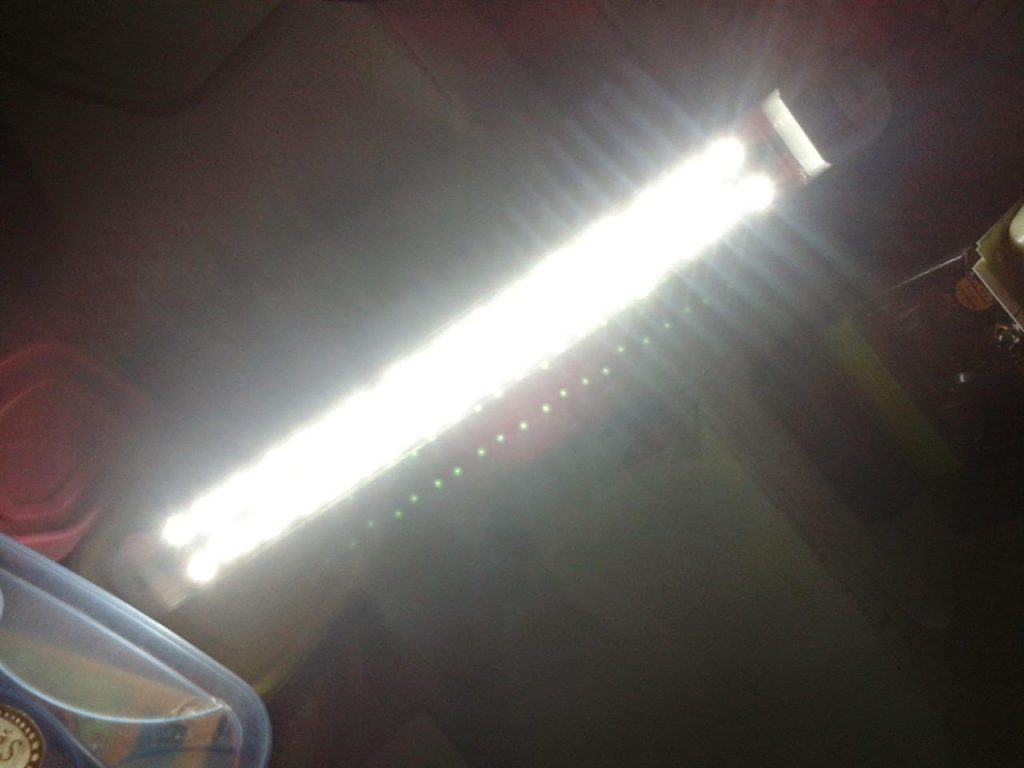
The above design was successfully built and tried by Mr. Ram, the following picture provides a dazzling performance proof for the same.
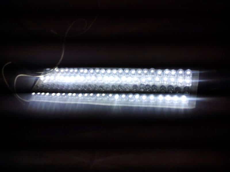
The circuit was also built and tested by Mr. Raj, who is also an avid follower of this blog, the picture below was sent by him for the readers viewing pleasure.
Another LED String Light using a Single Capacitor
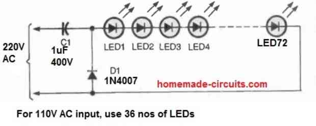
Our first LED light string includes 72 LEDs linked in series, as seen in the accompanying image. The capacitor and the diode should be placed in an insulated container, while the LEDs must be contained in a piece of transparent pvc pipe.
You could wish to use small bits of small-gauge, shielded, thin wire between the LEDs to spread them out throughout the length of the tube.
The circuit works as simply as it possibly can.
1uF 400 volt capacitor C1, which is linked in series with the LED string, serves as a no-loss, AC current-limiting element of the circuit.
The reactance of the capacitor behaves just like a resistor to the AC current without incurring the losses associated with a typical power resistor. The 1N4007 silicon diode shields the LEDs from harm caused by reverse voltage.
All the LEDs can be 5mm, 20 mA high bright white LEDs.


Questions & Answers
Regarding the 2nd circuit (single capacitor) I have aa few questions:
1. Why specifically 72 LEDs? What happens if I use 60 or 90 LEDs in the series?
2. What is the output voltage after mains supply goes through C1? It is still AC I suppose which is somewhat equivalent to 310V DC?
3. The output voltage increases after C1 increases during power surge of mains?
4. Another capacitor can be used in parallel with D1 to reduce LED flickering. What should it be?
You can use any number of LEDs right from 1 to 100, but maybe not above 100, because 100 * 3 = 300 which is the max peak voltage available from a 220 V supply.
Just make sure that the capacitor is selected as per the max current rating of the LED.
A 1uF can supply 50mA current, so with this benchmark select the capacitor value whose max current does not exceed the LED rating.
Also, to suppress switch-ON surge make sure to use a series NTC with the capacitor.
Yes, another 400V capacitor can be used parallel to the diode for reducing flickering…
Output of c1 will be 300v at 17mA max current. If load pulls more current then voltage will decrease as per V=IR. So 1 LED will burn out at 300v unless a suitable resistor is used in series.
Correct me if Im wrong.
Why will the load pull more current than its specified rating?
Load will pull more current only if input voltage increases, in that case a current controller would be required.
Nobody said load will pull more current than its “rating”. I meant if a different load which pulls more current than 17mA is attached, the voltage will drop.
Alternatively…474j capacitor followed by single in4007 diode followed by LED series with a parallel smoothing capacitor is enough to light them up…what say?
This string light circuit is designed only for calculated series LEDs, so connecting any different load may not be recommended. And if the voltage drops, the LEDs will stop illuminating, they will not burn.
A single 1N4007 will not work, it has be two 1N4007 connected in series/parallel or a bridge rectifier, because the 474 cap needs to discharge alternately for each AC cycle. Bridge rectifier is better..
Swagatam,
Instead of the Cap, if I just use an appropriate power resistor, will it also work? I want to make a matrix of 8×9=72 LEDs, all in series. How much resistance and of what wattage rating will be required?
Yes, resistor can be used instead of the capacitor, but it might dissipate a lot of heat.
8×9, meaning 8 in series and 9 of these in parallel? Is that correct?
no I meant all in series. what will be the suitable resistor rating? if I divide 220v by 3v, it comes to around 73 LEDs. if I use 73 LEDs do o get a benefit in terms of power dissipation and will a low power resistor work?
OK, but you must consider the peak 310 V while doing the calculations. 220 is the RMS value.
Here’s formula for calculating the resistor value:
R = [310 – (number of LEDs x 3)] / LED max current limit
Resistor Power = [310 – (number of LEDs x 3)] x LED max current limit
You precisely clarified my doubt. I was wondering whether the calculations should be done on 220v or the RMS value 310v. So for 64 LEDs the need would be of a 5.9K resistor with 2.36w or more current rating, I am guessing 2 parallel 6.8K 5W resistors will solve the purpose. Thanks a lot for being the guide needed by hobbyists like me! অসংখ্য ধন্যবাদ তোমাকে! 🙂
Did u make this? Did the LED chain last long enough?
with a calculated resistor the LEDs should last very long, because with a resistor there won’t be any surge current risks, dissipation also will be negligible if the number of LEDs are matched according to the peak voltage of the input AC.
I am glad I could help you! Yes a single 6.8K 5 watt should work perfectly. Unfortunately I cannot read or write Bengali, I can only speak 🙂
sorry I didn’t mean 2 parallel resistors, I meant one 6.8k 5w resistor..
Can you kindly advice how to build this circuit with 10 mm LEDs and be reliable
you can use 10mm leds with the above circuit….just make sure the capacitor current is not higher than the LED current.
Yahya Zakaria
Can you kindly advice about using the beautiful circuit with 10 mm LEDs
Hi, I like to connect a series of normal 5mm white or blue LEDs directly to 220v AC main. Pls suggest me a circuit for that.
A string of LEDs consists of 5-15 LEDs. So the string may contain 8 or 10 or 12 LEDs. The circuit should give proper voltage to the LEDs.
the zener volatge will need alteration as per the number of lEDs
zen V = 3.3 x no. of LEDs
Hi, you can try the following circuit for your LeDs
https://www.homemade-circuits.com/2011/12/cheap-yet-useful-transformerless-power.html
replace C1 with a 0.33uF/400V to reduce surge in rush
Dear Mr. Swagat,
good morning, I appreciate the way you guide. I have two questions-
1. you wrote that 90 leds will be adequate and safe so it means two strings of 45 leds (total 90 leads) or two strings of 90 leds (total 180 leads)
2. pl give an idea how much light this circuit will give in comparison to incandescent bulb in watt/lumens
I have one more request pl share a circuit using 1 watt led or 10 watt led that can replace 100 watt incandescent bulb. it would be nice if it is mains operated without transformer if not necessary. its ok if it is dc operated using 220 v secondary.
Thanks, Sudhir
Thank you Sudhir,
It should be a string of 90 LEDs, not two strings of 45 LEDs.
More strings of 90 LEDs can be connected in parallel, but that might require the input capacitor value to be upgraded accordingly.
LEDs are hugely efficient than the traditional incandescent lamps therefore the light could be much brighter, around 80% more brighter.
I already have one related circuit in this website, you can refer to it for more info, here's the link:
https://www.homemade-circuits.com/2014/04/simplest-100-watt-led-bulb-circuit.html
thanks……
sir, I'm using about 4 to 5 led drivers given on this blog & its working very well. I couldn't find any capacitor on the circuit board of that lighting excepting diode bridge so I tried it. Ok. now want to know, is 0.22uF ppc cap & diode bridge sufficient to drive a single 5mm white led? or is it need to add an electrolytic cap at output?
You are welcome Ganesh!
thank you so much Swagatam sir.
I am getting very much help from ur blog. and most important thing is, you communicate with everyone who needs proper guidence. I m so thankful of this blog & you.
I will come again with my next difficulties.
Thank you so much sir.
Have a nice evening!
0.22uF will provide roughly 10mA to 12mA current so that might not be enough for 5mm 20mA LED, you can try 0.33uF/400V capacitor with a bridge rectifier
…a filter capacitor can be added to make the glow smooth without flickering, and also add a 3.3V zener in parallel with the LED for max protection.
Ok Thanks so much
connecting it directly would cause the high current from the mains to enter the LEds and destroy them immediately.
Hi Ganesh,
why did you connect it directly to the AC mains??? you should have done it through a high voltage capacitor as indicated in the above figure and in the following article:
https://www.homemade-circuits.com/2012/04/how-to-make-led-bulb-circuit.html
hi swagatam sir.
I m Shrinivas, I have purchased mains operated Led lighting with dual color led. the lighting has 54 no. of dual color led. when I opened the circuit box, there is only diode bridge. so I made 93 no.s led in series and connected it to main through only bridge as I found in that lighting. but as soon as I switch the button on, the fuse on the power plug as well as main line board blown. I wonder why this happened. can u figute out this problem sir?
Hello sir….. I want to run 100 8mm led of White in SERIES at 230v AC main so wat will be the circuit for that
Hello Basit,
you can use the following circuit, just modify the input cap value to 0.47uF/400V
https://www.homemade-circuits.com/2014/04/simplest-100-watt-led-bulb-circuit.html
If one rectifies 110 US mains, one gets 180V DC.. It is best to value max voltage at that, and bright white 5mm often have a 1.8 to 2.2 v FVD.. Meaning 90 of these 2 volt LED's in each direction, typically using 20 mA each. My question is, do we value power consumption in one direction, or both? 3.6 Watts or 7.2??
It's in one direction but for both the half cycles…so 3.3 x 90 x .02 = 5.94 watts
Please remove the previous comment. That was probably a faulty capacitor. Now its working, although the flickering is slightly noticable.
Here is a picture; postimg.org/image/k0tfh6dab/
I'll update the image soon in the article…thanks!
That's great Raj, the flickering will be there due to the absence of a rectifier and a filter stage.
I did not delete the previous comment just to maintain the comment sequence and allow the readers to know about the proceedings correctly.
Helo Swagatam, yesterday I made the circuit shown above with 100 x 5mm LEDs. The only difference was the capacitor, which was rated at 650volt/1200volts instead of 400volts as shown. Now, when I give AC supply, the LEDs are very dim, why is that?
Hi, I have found my problem, which are:
1. My multimeter probes have a resistance of 1.3 ohms, which was adding up when I was measuring the resistors.
2. The breadboard on which I was working also had an internal resistance which was also adding on the total value.
These two factors took a lot of my time, so I would request you to add these points in projects like 'constant current limiter circuit' where we have to deal with very small amount of resistances.
About my project, I have successfully finished building a circuit for lighting my 20Watt LED. The circuit is, a 12V adapter, then a voltage booster circuit, then the LM317, then the LED. Since the LED needs about 30V, so the voltage booster is necessary.
Total cost was about Rs.300/-, without the adapter and LED.
nice, glad to know about it, thanks for updating the info.
I think I will go with LM317 on each LED. Can you give me a link where mica isolators are found online? It is not available locally.
Another question, have you ever used those big 5watt resistors? I bought 3 for 0.5ohm and on measuring found all of them to be around 1.5ohm. Another 1ohm 5W resistor is showing 2.7ohm ('1E' written on resistor). Are these type of resistors unreliable? Or is my multimeter not capable of measuring such small values?
OK, that's great.
if you Google "mica insulator kit for transistors buy" you'll come across many relevant links.
the resistors may not be too accurate with their values, but in your case it's definitely the multimeter that's not showing the correct value, and anyway no multimeter will be capable of measuring such small values in their normal Ohm, or kOhm range…unless these are equipped with a milliohm range.
alternatively you can use 1 ohm, 1 watt carbon resistors in parallel for achieving the desired value, this will allow you to get more accurate and manageable results
These are a typical 10 watt LED ratings:
Model – 10 watt.
Color – White.
Forward voltage (VF) DC 9 – 12v.
Forward current (IF ) – 1050 MA.
Output lumens – 800 – 900LM.
Life span – 50,000 hours.
operate voltage – 9v to 12v DC.
…if you are not interested to connect each IC for each LED, you can opt for the following alternative current control design:
https://www.homemade-circuits.com/2011/12/make-hundred-watt-led-floodlight.html
if the power of the psu is rated to handle well above 200 watts then you can use it for the mentioned purpose, you can connect all the modules in parallel across the output of the power supply.
And yes using LM317 in series for each module would be great, and would provide maximum safety against over-current.
If possible mount the ICs over the same heatsink which are used for the LEDs, this will ensure extra thermal protection for the LEDs.
But make sure the IC is separated from the heatsink with a mica isolator to avoid a short circuit
Regarding using a computer psu to run a large number of LEDs, say, I want to run 20 x 10W LEDs; can I connect all the 20 LEDs in parallel to the 12V supply? How will the current be controlled? Since the LEDs are in parallel, connecting a LM317 for each LED is not feasible.
Thanks Raj, however the above circuit is not recommended for high wattage LEds, it may be suitable only for low current, high quantity LEDs as depicted in the above article.
for your case you will have to opt for an SMPS adapter, heatsink, current controller etc….. and these are not much complicated, I have comprehensively covered all these parameters in this blog,
Great idea for running LEDs directly on AC. I think most people turn away from LED lighting because the need for an adapter.
Can you please help me out here? I need to run 4 no. of 10watt LEDs. How to modify the circuit?
Also, how long will the LED survive without a current limiter and in a 50Hz supply?