Today I am going to share a very useful and clever circuit diagram sent to me by Mr. August Peterson. This circuit is a non-contact HT spark tester and timing light tool. It is specially designed for modern cars where checking for a spark is very difficult and dangerous for the car electronics.
Why Mr. August Designed This Circuit
In modern vehicles, especially those with coil on plug systems, you cannot easily touch or access the high tension HT cable. Also, pulling out the spark plug cable and holding it near the engine ground to see a spark is a bad idea. When the spark gap increases, the secondary coil voltage jumps up very high.
Before we get into the circuit details, here is the original message and explanation sent to me by Mr. August:
Hi Swagatam, Here is another circuit for your consideration. It was developed for the following reasons:- 1) It is not a good idea to pull a spark plug lead from the plug and check for a spark to ground. When the gap increases so does the secondary coil voltage and this can cause an internal coil short circuit. On a transistor ignition it could be induced into the coil primary and destroy the ignition electronics. 2) On a coil on plug system, you cannot access the HT section of the coil. 3) Timing lights that connect to the HT lead can no longer be connected beacause the HT lead is not accessible. The sensor plate in the circuit is any metal plate because it capacitively coupled to the car HT system. The metal plate sensor can be covered in insulation tape for safety if desired. To avoid stray pickup, the lead to the sensor should be a shielded cable, grounded at the circuit board. The potentiometer is to adjust the sensitivity so that a weak HT can be identified from a strong HT signal by reducing the sensitivity and comparing until the faulty HT is located by no flashing of the red LED. To operate, connect the circuit to the car battery, run the engine, hold the plate on an HT lead or a coil pack and adjust the pot to provide a flashing red LED indicating the presence of HT voltage. To use the timing light, hold the sensor on HT lead oe coil pack #1 and plug the white LED into the socket. Adjust the sensitivity to obtain a flashing white LED. The white LED is mounted on a 6mm plastic tube of about 300mm long so that it can reach close to the timing marks. This is a cheap and useful addition to any home mechanics toolkit. Please let me know if I have not explained well enough. Regards August
How the Sensor Works
This high voltage spike can break the internal insulation of the coil or feed back into the transistorized ignition module and burn expensive ECU electronics.
Secondly, standard old timing lights need a direct connection to the HT lead, which is impossible when there is no exposed lead.
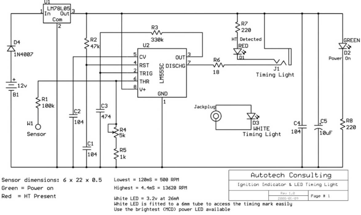
To solve this problem, Mr. August created a simple capacitive sensor circuit using an LM555 IC. The sensor is nothing but a simple metal plate. You can wrap it in insulation tape for safety.
The lead from the plate to the circuit board must be a shielded wire with the shield connected to ground so it does not pick up stray electrical noise.
When you hold this metal plate near an HT lead or a coil pack, the high voltage pulse capacitively couples a tiny signal into the sensor without making any physical electrical contact.
Circuit Operation and Pulse Stretcher Details
Now let us see how the circuit works internally. The car battery voltage goes through a 1N4007 protection diode D4 to prevent damage from reverse connections. Then an LM78L05 regulator IC drops the voltage to a clean 5V to power the circuit stably.
The signal from the sensor goes through a 100k resistor R1 to the trigger pin 2 and threshold pin 6 of the LM555 IC. A 5k potentiometer R4 along with a 1k resistor R5 forms a sensitivity adjustment network.
By tuning this potentiometer, you can set the trigger threshold. This helps you compare a weak spark with a strong spark across different cylinders.
Since the actual spark pulse lasts only a few microseconds, our human eyes cannot see the LED blink. So the LM555 IC is configured as a monostable pulse stretcher. In the schematic, resistor R3 is 330k and capacitor C3 is 474 which is 0.47uF.
Whenever a spark signal triggers the chip, it stretches the tiny microsecond pulse into a long output pulse of around 170 milliseconds. This makes the red HT Detected LED flash brightly and clearly.
Timing Light Socket Assembly
There is also a jack socket provided for an external timing light. A high brightness white LED is connected to a plug and mounted on a long plastic tube about 300mm long.
You can hold this white LED close to the timing marks on the engine while keeping your hands safely away from moving belts and pulleys.
My Technical Analysis and Recommendations
Now coming to my analysis of this circuit. Overall this is a brilliant, cheap, and very safe tool for any home mechanic. However, there are two important technical points you should keep in mind if you build it.
First point is about the pulse duration. With R3 at 330k and C3 at 0.47uF, the output pulse stays high for nearly 170ms. This is perfect for checking whether a spark is present or missing at idle or low RPM.
But at higher engine RPMs, the sparks happen so fast that 170ms is too long, and the LED will stay permanently ON instead of flashing. If you want to use it as a proper timing light at higher engine speeds, you should reduce C3 to a lower value like 0.047uF or 0.1uF so the flashes become sharp and distinct.
Second point is regarding the IC choice. In this circuit, the timing light jack connects to Pin 7 DISCHG to sink current for the white LED. You must strictly use a standard bipolar LM555 or LM555C IC for this project.
Do not use CMOS versions like LMC555, TLC555, or ICM7555, because the internal discharge transistor in CMOS chips cannot sink high current on Pin 7 and will get damaged or fail to light up the LED properly.
LED Test Light Circuit For Safely Testing Modern Vehicles Electrical and Electronics
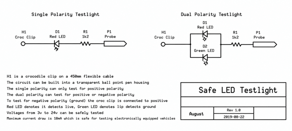
Another simple automobile wiring tester was designed and contributed to this site by Mr. August Peterson. Here are the complete details of the circuit as explained by the creator himself.
Hi Swagatam, Another automotive circuit for your consideration. A vehicle without electronics can be tested using a filament type testlight. The cold resistance of the bulb is about 4.8 Ohms. At 12v the instantaneous current is about 2.5A E.G. if this is used to test a Hall type distributor (VW Golf etc.) the Hall sensor will be immediately destroyed because it's max load is 20mA. Similarly, it is dangerous to use a filament testlight on any modern vehicle that contains electronics so an "electronic" testlight should be used. The attached LED testlight can be easily and cheaply constructed to enable safe testing of vehicles with on board electronics.
Conclusion
Big thanks to Mr. August for sending this practical design to share with our community. Build these circuits and let me know your thoughts in the comment section below.
I am an electronics engineer and doing practical hands-on work from more than 15 years now. Building real circuits, testing them and also making PCB layouts by myself. I really love doing all these things like inventing something new, designing electronics and also helping other people like hobby guys who want to make their own cool circuits at home.
And that is the main reason why I started this website homemade-circuits.com, to share different types of circuit ideas..
If you are having any kind of doubt or question related to circuits then just write down your question in the comment box below, I am like always checking, so I guarantee I will reply you for sure!
Good evening.
I am trying to build the circuit shown above, but I suspect there might be an error in the design—specifically regarding the IC555 pins. Shouldn’t the pulse input go into pin 2 rather than pin 6, with the output at pin 3?
Or perhaps there is a specific method being used here that I do not yet understand.
Thank you in advance.
Good evening! You are completely right, there is a drafting error on the diagram. You can easily fix it by simply swapping the label for pin 2 and pin 6 on the IC. Once you flip those two pin numbers, the schematic becomes a standard and working 555 monostable circuit. Thanks for pointing this out!
Need Help? Please Leave a Comment! We value your input—Kindly keep it relevant to the above topic! Cancel reply




Questions & Answers
Good evening.
I am trying to build the circuit shown above, but I suspect there might be an error in the design—specifically regarding the IC555 pins. Shouldn’t the pulse input go into pin 2 rather than pin 6, with the output at pin 3?
Or perhaps there is a specific method being used here that I do not yet understand.
Thank you in advance.
Good evening! You are completely right, there is a drafting error on the diagram. You can easily fix it by simply swapping the label for pin 2 and pin 6 on the IC. Once you flip those two pin numbers, the schematic becomes a standard and working 555 monostable circuit. Thanks for pointing this out!