A single state-of-the-art chip, a transistor and a few other inexpensive passive components are the only materials required for making this outstanding, self regulating, over charge controlled, automatic NiMH battery charger circuit. Let’s study the whole operation explained in the article.
Main Features:
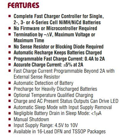
How the Charger Circuit Works
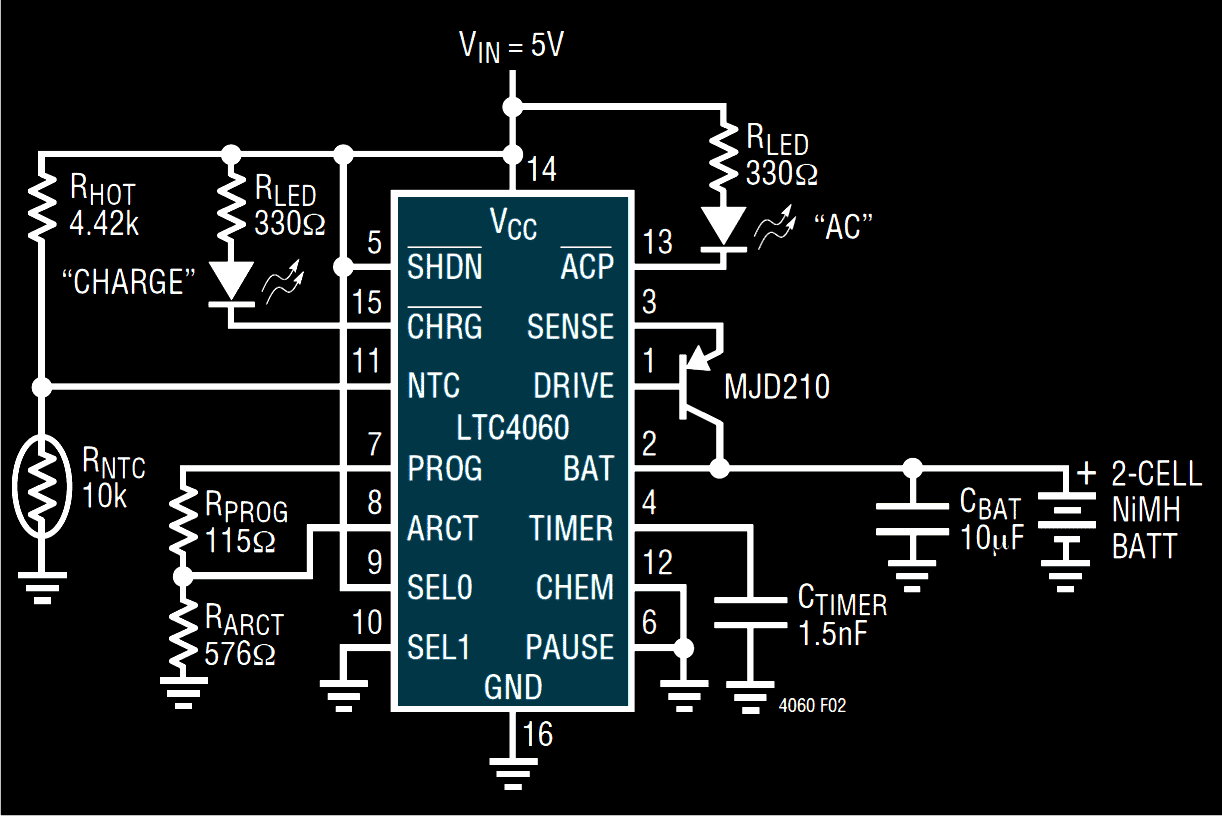
Referring to the diagram we see a single IC being used which alone performs the function of a versatile high grade battery charger circuit and offers utmost protection to the connected battery while it’s being charged by the circuit.
This helps to keep the battery in a healthy environment and yet charge it with a relatively rapid rate. This IC ensures a high battery life even after many hundreds of charging cycles.
The internal functioning of the NiMH battery charger circuit can be understood with the following points:
When the circuit is not powered, the IC enters into a sleep mode and the loaded battery is disconnected from the relevant IC pin out by the action of the internal circuitry.
The sleep mode is also triggered and the shut down mode is initiated when the supply voltage exceeds the specified threshold of the IC.
Technically, when the Vcc goes above the ULVO (under voltage lock out) fixed limit, the IC triggers the sleep mode and disconnects the battery from the charging current.
The ULVO limits are defined by the potential difference level detected across the connected cells. This means the number of cells connected determines the shut down threshold of the IC.
The number of cells to be connected must be initially programmed with the IC through suitable component settings; the issue is discussed later on the article.
The rate of charging or the charging current can be set externally through a program resistor connected to the PROG pin out of the IC.
With the present configuration an inbuilt amplifier causes a virtual reference of 1.5 V to appear across the PROG pin.
This means that now the programming current flows through an in built N channel FET toward the current divider.
The current divider is handled by the charger state control logic which produces a potential difference across resistor, creating a fast charging condition for the connected battery.
The current divider is also responsible for providing a constant current level to the battery through the pin Iosc.
The above pin out in conjunction with a TIMER capacitor determines an oscillator frequency used for delivering the charging input to the battery.
The above charging current is activated through the collector of the externally connected PNP transistor, while its emitter is rigged with the IC’s SENSE pin out for providing the charging rate information to the IC.
Understanding the pinout functions of the LTC4060
Understanding the pin outs of the IC will make the building procedure of this NiMH battery charger circuit easier, let's go through the data with the following instructions:
DRIVE (pin #1): The pin is connected to the base of the external PNP transistor and is responsible for providing the base bias to the transistor. This is done by applying a constant sink current to the base of the transistor. The pin out has current protected output.
BAT (pin #2): This pin is used to monitor the charging current of the connected battery while it is being charged by the circuit.
SENSE (pin #3): As the name suggests it senses the charging current applied to the battery and controls the conduction of the PNP transistor.
TIMER (pin #4): It defines the oscillator frequency of the IC and helps to regulate the charge cycle limits along with the resistor that’s calculated at the PROG and GND pin outs of the IC.
SHDN (pin #5): When this pin out is triggered low, the IC shuts down the charging input to the battery, minimizing the supply current to the IC.
PAUSE (pin #7): This pin out may be used for stopping the charging process for some period of time. The process may be restored by providing a low level back to the pin out.
PROG (pin #7): A virtual reference of 1.5V across this pin is created through a resistor connected across this pin and ground. The charging current is 930 times the level of the current that flows through this resistor. Thus this pinout may be used for programming the charging current by altering the resistor value appropriately for determining different charging rates.
ARCT (pin #8): It’s the auto-recharge pinout of the IC and is used for programming the threshold charge current level. When the battery voltage falls below a preprogrammed voltage level, the charging is reinitiated instantly.
SEL0, SEL1 (pin #9 and #10): These pin outs are used for making the IC compatible with different number of cells to be charged. For two cells, SEL1 is connected to ground and SEL0 to the supply voltage of the IC.
How to Charge 3 Series Number of Cells
For charging three cells in series SEL1 is rigged to the supply terminal while SEL0 is wired up to the ground. For conditioning four cells in series, both the pins are connected to the supply rail, that is to the positive of the IC.
NTC (pin #11): An external NTC resistor may be integrated to this pin out for making the circuit work with respect to the ambient temperature levels. If the conditions become too hot the pin out detects it through the NTC and shuts down the proceedings.
CHEM (pin #12): This pin out detects the battery chemistry by sensing the negative Delta V level parameters of NiMH cells and selects the appropriate charging levels as per the sensed load.
ACP (pin #13): As discussed earlier, this pin detects the Vcc level, if it reaches below the specified limits, in such conditions the pinout becomes high impedance, shutting down the IC in sleep mode, and shutting off the LED. However, if the Vcc is compatible with respect to the battery full charge specifications, then this pinout turns low, illuminating the LED and initiating the battery charging process.
CHRG (pin #15): An LED connected to this pin out provides the charging indications and indicates that the cells are being charged.
Vcc (pin #14): It’s simply the supply input terminal of the IC.
GND (pin #16): As above it’s the negative supply terminal of the IC.


Questions & Answers
Good day Mr Swagatam.
I need to charge three AA NiMH cells in series with a six volt four watt solar panel. I use the solar panel and connect it to a dc dc step up boost converter. The boost converter ensures that there is always enough volts going to the three AA NiMH cells in my cordless PIR alarm transmitter in my garage. The solar panel, dc dc boost converter and PIR alarm transmitter are off the shelve items. I have tested the above mentioned setup and it works beautiful, but it lacks a over charge cut out and battery discharge or when to start charging the batteries circuit. So i need a circuit that i can add on between my boost converter and the batteries of my PIR alarm transmitter. This over and under charge circuit must only use transistors and no relay, as the relay coil will use to much power from my existing units. The over and under charge circuit must only have one led to indicate that batteries are being charged and as soon as the batteries are fully charged, the led must turn off.
So i have a 6 volt, 4 watt solar panel connected to a dc – dc step up boost converter, then your battery over charge and when to start charge circuit and then the 3 in series AA NiMH to be charged in my PIR alarm transmitter. It is a transistor based over charge and over discharge protection circuit with no relay and only 1 led to show when it is charging, that i need.
I hope that my explanation of the circuit that i need makes cense.
Thank you.
Thank you Ian.
I will propose a rather simple circuit which should do the job for you, because other precision circuits will need opamps and presets and can be very complicated to build and set up.
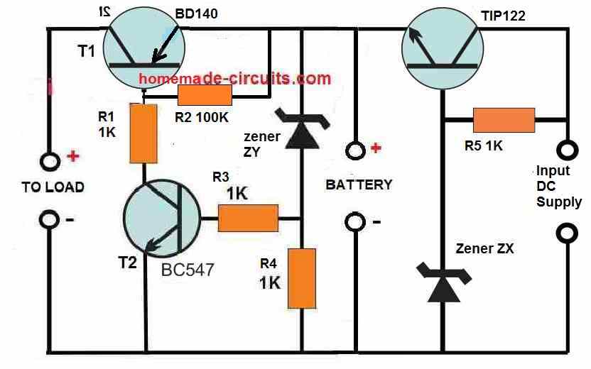
You can try the following transistorized design for your application.
You will have to adjust zener ZX value such that the emitter of TIP122 generates a voltage that’s exactly equal to the battery fully charge level. While doing this keep a 1K resistor connected between the battery points but without any battery connected. After the zener is set, the 1K can be removed.
Similarly adjust the ZY zener value such that the T1 or the BD140 is just cut off when the battery level drops to its low battery voltage value. For this you can connect an LED with a series resistor across the load terminal. This LED should shut off at this ZY zener value.
For the above adjustment make sure to connect an external DC supply across the load terminals which is equivalent to the battery low voltage value.
However there’s no provision for putting an LED that will show the battery is charging.
Good day Mr Swagatam.
Sorry it’s me again. Will you please design me a circuit as follows.
I have 6 Volt 4 Watt solar panel that i connect to a DC – DC step up boost converter to ensure that there is enough power output, even on a cloudy day. The output from the DC- DC boost converter will be connected to your op-amp over charge and over discharge protection circuit to charge 3 x 2100 mA NiMH batteries in series. Your op-amp circuit must have 2 led’s , one led to indicate when the batteries are busy charging and this led must go out and disconnect the boost converter as soon as the batterie are fully charged at 4,35 +/- volts. The second led must light up as soon as the batteries reach a discharge voltage of 2,7 Volts and then your op-amp circuit must also disconnect the battery from my alarm( load)
Thank you Sir.
I can design it but I bet you will never be able to set it up correctly, because it will require an expert knowledge of battery charging and op amps.
Okay Mr Swagatam, i will build this circuit again, maybe there is a fault in my build that i just can not find.
For ZX, what voltage must the Zener diode be so that TIP122 stops the charging of the battery at minimum 4.35 volt and maximum 4.7 volt. ( 3 X AA NiMH 2100 mAH IN SERIES.) For testing the working of TIP122 that it cuts out at the above mentioned voltage, must i connect a 1 K ohm resistor in the place of the battery and test with a DDM over this resistor to measure the charge cut off voltage. And connect my variable dc power supply over the input dc supply and adjust it’s voltage to see on the DDM at what voltage Tipp122 cuts out the charger?
For the ZY, what voltage value do you suggest so that BD140 disconnects the battery from the load at NO LESS THEN 2,7 Volts. And to test ZY and BD140 cutout, where must i connect my variable DC supply to and where must the LED with series resistor be connected. You mentioned that i must connect my power supply like this…… IN BRACKETS IS YOUR TEST PROCEDURE. ( Similarly adjust the ZY zener value such that the T1 or the BD140 is just cut off when the battery level drops to its low battery voltage value. For this you can connect an LED with a series resistor across the load terminal. This LED should shut off at this ZY zener value.
For the above adjustment make sure to connect an external DC supply across the load terminals which is equivalent to the battery low voltage value.)
I do not understand the above procedure, led with series resistor and power supply connected at load????? Please help with the ZY LED and power supply connection points for testing/setting ZY.
Thank you sir.
Let’s consider the full charge voltage of a single 1.2V NiMH cell is 1.5, so for 3 in series it will will be approximately = 4.5V Max. The TIP122 might drop around 1V. So the value of the ZX should be around 4.5V + 1 = 5.5 V.
While checking this voltage at the emitter, keep a 1k connected connected across emitter/ground of the TIP122.
The above voltage should be constant at 4.5V regardless of how high the input DC supply is.
It is not possible to test the cut off without a battery, because cut of will happen naturally when the battery is charged to the 4.5V level. If you connect an ammeter between the TIP122 and the battery positive you will find that as the battery charges the ammeter needle slowly drops towards zero and at full charge it drops fully at zero, indicating that no current is flowing to the battery.
Yes, I am sorry for the slightly wrong explanation. For the ZY adjustment, the LED should be across the load points, and the DC supply should be across the battery points.
For ZY you can try a 3.3 V zener diode, or you can try 7 nos of 1N4148 diodes connected in series in place of the ZY. The anode will be towards the battery positive and the cathodes towards the 1K junction.
Let me know how it goes, if you are not satisfied then we can perhaps proceed with the opamp version, in a step wise manner.
Good day MR Swagatam.
According to the measurements that i have taken from my circuit, IT WORKS… YIPEEE.
I must now just play a bit with the ZX Zener diode value to fine tune the charge voltage.
There is now one more question about the ZY Zener diode. The circuit diagram shows that the ZY cathode points to the positive rail between TIP122 emitter and BD140 emitter, the anode point toward the two 1 K ohm resistor junction, but above you now say it must be the other way around?
Pleas clarify this Sir.
Thank you for all your help and patience with me, i really appreciate all your help.
Thanks Ian, glad it is working now.
For ZY if you are using a zener diode then the cathode will be toward the positive line and anode will be toward the 1K resistors, if you replace it with a few numbers of 1N4148 diodes in series then the polarities will be just the opposite. Each 1N4148 will drop around 0.6V, so 5 in series might drop around 3V, which would mean if the battery voltage dropped below 3V, the BC547 and the BD140 would cut off.
You can also connect an LED in series with the base of BC547 for indicating the load supply cut off. Cathode will go toward the transistor base, and the anode toward the 1K junction.
Good day.
Mr Swagatam this circuit does not work. I have triple checked all my connections and every thing is correct with my circuit. At the base of TIP122 I have tested with a 4,7 volt and a 5,6 volt 0,5 WATT zener diodes. I have connected a1 k ohm resistor where the battery should go and my bench power supply at the input dc supply of the circuit. I also connected a DDM across the 1 K ohm resistor at the batteries spot and a DDM across the input, i then adjusted my power supply to see if the TIP 122 will cut out at 4.7 volt, but it did not. I can adjust my power supply from 0 to 15 VOLT and i can see on the battery DDM that the voltage is slightly lower than the input volts but never goes higher than 4.1 volt and never cuts out. At the over discharge cut out side i have connected my power supply first to the load side, like you said and then to the battery side with an led connected, but it never cuts the load from the battery. My ZY zener diode is 2.7 volt. I want to charge 3 AA NiMH 2100mA in series with a 6 volt 4 Watt solar panel. I have a 6 Volt 4 Watt solar panel and connect that to a DC TO DC step up boost converter to ensure that there is always enough power, even on a cloudy day. I have no over charge or over discharge protection. I have build many of your circuits in the past and this is the first time that i found that the circuit does not work.
Do you have a op amp circuit that i can use for my set up, described above.
Hello Ian,
This circuit will definitely work because it has as to work as per the standard rules of the transistor working.
I will try to explain you briefly how the circuit is supposed to work.
When a battery is connected across the voltage from the emitter of TIP122, the emitter voltage will drop to the battery discharge level and the battery will start charging, and then at full charge level when the battery terminal voltage becomes equal to the emitter voltage of TIP122, the current can no longer flow from the TIP122 emitter to the battery side because the two voltages are identical, and the battery stops charging any further. This is how and where the automatic cut off happens.
Now, for the load current cut off function, when the battery voltage drops below the ZY zener level, the zener diode stops conducting. When ZY zener stops conducting it cuts off the current at BC547 base which in turn stops conducting. With BC547 cut off the BD140 can no longer get the negative base bias and it also cuts off. The load supply is now cut off
The above functioning are impeccable and has to work.
I have a few op amp charger circuits but they can be much complex to adjust and set up for a newcomer.
Op amp Battery Charger Circuit with Auto Cut Off
IC 741 Low Battery Indicator Circuit
USB 3.7V Li-Ion Battery Charger Circuit
Good day Mr Swagatam.
I just want to know how many milli amps does this circuit consume from the battery alone with no charger, solar panel or a load connected to it. I have 4 NiMH AA cells in series as a battery bank. 2000 mAh AA cells. I have used zener 6.8 v and 4.3 v 500 milli watt diodes for the over charge and over discharge to switch the transistors. Thank you Sir
Hi Ian,
the consumption of this circuit depends solely on R1. It could be a few milliamps. The 1K value has been selected randomly, a higher value could be chosen to reduce the current consumption further down.
…But we cannot expect the cut off functions to happen sharply, they will happen gradually as the voltage levels reach the respective marks.
I want to power this cicuit via a solar panel to maintain charge in 4xNimh 1.5v batteries in my cat flap. Will i need to use a controller between the panel and charger circuit?
Thanks
You can use a 7809 voltage regulator IC between the solar panel and the above battery charger module…
Hy Swagatam,
Have You a schematic for recharging Ni-MH batteries with capacitors by means a Joule Thief circuit?
I designed one for a particular application but I am not sure it with all safety precautions as for IC as above.
I should power up a 12V microfan and 4 (four) white LEDs, by storing the energy for the battery from the supercaps, loaded with a surplus of energy coming from the nulling of back EMF by the bucking winding of the transformer.
Can You support me thereabouts?
Thanks and regards,
Riccardo Tarelli
Hi Ricardo, the energy from the back EMF has to be significantly strong to be able to charge the Ni-Mh cells.
If it is, then you can use any standard joule thief circuit, by upgrading its current rating through thicker coil winding and adequately rated transistor.
If you can provide the specifications of all the parameters, including the back EMF, I may try to solve it for you!!
Hy Swagatam,
Certainly when I completed the design I will announce this to You in order to check if something has gone wrong! : -)
I hope to be successful with your precious support! 🙂
Thanks and regards,
Riccardo
No problem Riccardo, I wish you all the best with the project!
If we are using 5V regulated supply, then can we leave the ACP pin empty?
yes, but the Vcc must be higher than the total full charging voltage of the batteries, otherwise the IC shut down and go to sleep mode
Ok, but I am charging 1.2×2 batteries, so 5V is enough?
Am I right?
Also giving a current about 2300 mAh. Is that current value is fine?
Then 5 V is OK, you can remove the pin13 components. Please check the datasheet to find the maximum current of the circuit.
Sir, I started the project, Now came into trouble, I don’t have much experience with electronics, plz guide me to choose the max. Current limit for IC4060?
Daniel, the circuit diagram shown in the above article will fast charge your 2400 mAh battery at 2 amp rate, so you can apply the shown design
If we are using 5V regulated SMPS supply, then what’s the need of AC diode portion, I mean we can connect 13th and 14th pin directly without resistor and LED?
Is that fine?
in 13 is the undervolatge lockout indicator. If the supply Vcc is less than the battery full charge then the IC will shut down, and the ACP LED will be off.
Instead of using ceramic type for 1.5nF, Film capacitor are very accurate than ceramic?
Am I right?
Yes that’s right!
1.5nF is ceramic type?
yes ceramic will do!
Sir some of the values of the resistor is not available in market??
What to do?
You can adjust the values by adding series parallel resistors….
Like 2.2k+2.2k+0.01k+0.01k=4.42k
Is that correct?
Yes that’s correct, you can use any combination that may be available with you.
But If used 4 capacitor in series, will it affect the circuit because number of capacitors are relatively high?. Otherwise can I use directly 4.7k ohm resistor?
Sorry Sir, Resistor…Typing mistake
It won’t matter, you can use any number of resistors, only the value needs to exact.
capacitors or resistors!
The above capacitor is electrolyte type?
The 10uF is electrolytic
What about other capacitor?
Sir which type of capacitor is this?