In this post I have explained how to set or adjust an opamp 741 IC based battery charger circuit for implementing an automatic cut-off for the connected battery once it reaches the full-charge level.
Since I have many such IC 741 battery charger circuits posted here, the instructions will be helpful for correctly setting up most of those relevant circuits. The query was put forth by Mr. Chaw.
How to Setup Charging Thresholds
I have finished with the universal Automatic 741 battery charger circuit prototyping. In order to test, can u explain me briefly about the settings for input and trimmers etc before i charge the battery ?
Let's say now I am going to charge Ni-MH 400mAh 7.2V battery:
(1) What is the power supply input voltage and current ? According to what u have mentioned, any voltage between 15-24V and 5A setting will do regardless of the battery voltage ?
(2) How can I predict and calculate my charging time to the battery ?
(3) What are the modification to 4k7 and 10k trimmer before charging ?
(4) Last but not least, if I want to add the LED showing the charging status, where should i add this to ?
I am sorry for asking too many questions, but thanks for all the way helping me out with my internship project. May god bless u for ur hardwork. Really appreciate it !! 😀
Video Explanation:
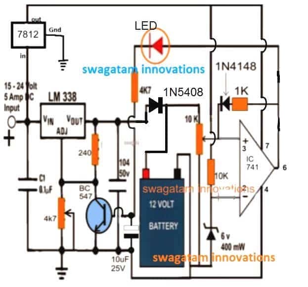
Circuit Diagram
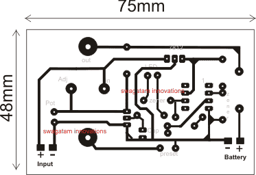
PCB Design
Analyzing the Circuit Query
Hi Chaw,
The instructions given below will help you to understand regarding how to quickly set up an opamp 741 battery charger circuit for an auto cut-off operation.
1) First disconnect the 1N4148 diode link connected at preset center arm and also the LED 4k7 resistor end from the base of the transistor. Connect this 4k7 end to ground temporarily.
2) Do not connect any battery as yet.
3) Feed an input voltage that may be at least 3 to 5V higher than the battery voltage.
4) Adjust the 4K7 pot to get a 8.5V across the terminals which is to be connected with battery.
5) Now adjust the trimmer such that the red LED just lights up.
That's all, your circuit is all set now
Reconnect the 1N4148 end with the preset center terminal as before and restore the LED 4k7 connection with the BC547 base.
You can now charge the battery from this charger and witness an auto cut off when the 7.2V reaches 8.5V.
The back up time will depend on the input current, if it's at the full 1C rate then you can expect the cell to charge within 1 hour or time.
you can add another LED across positive rail and pin#6 (for IC 741) with a series 1K resistor for the charging ON indicator
Estimating Charging Time
Yes noted, I have followed ur instructions to make a setting before charging. I have mentioned that I will made use of a 7.2V battery to test. In this case, may i know the purpose of why u advice me to get a 8.5V at the battery terminal ?
Like for example, if I were to charge another battery (12V,24V,etc...) with different voltage, how do I know the voltage that I should achieve ? Additionally, adjusting 4k7 trimmer to get 8.5V at the battery terminals (cathode of 1N5408 and ground), do I also need to get this voltage at the Vout pin of LM338?
Since my battery is 400mAh, I try to use 40mA for my input current because I got read from some of the comments that u suggested to use the input current which is five or ten times lesser than the battery mAh.
Thus, the time taken will be up to 4 hours to charge my battery, am I correct ? Is there any way to shorten my time taken like increase the input current in the other way ?
One more thing to clarify is that if I test with my multimetre to the battery terminals while charging, the voltage will keep on increasing after some time and when it reaches 8.5V, it will auto cut off the current and said to have a full charging ? I do apologize for so many questions every time sir.
Since I am still doing an internship, I want to understand in depth about all this project. I really do appreciate your patience to me 😀 With regards, Chaw
Charging a 12V Battery Optimally
For a 12V battery the recommended full charge level is 14.3V, so with this yardstick we can easily calculate the full charge levels of other batteries using the following simple cross multiplication formula:
12/V(Batt) = 14.3/V(full)
Here V(batt) is the normal batt voltage of any battery, and V(full) is the required full charge result.
the charging voltage should be measured and set after the diode cathode so that the diode FWD drop is countered appropriately, meaning the LM338 terminal voltage will be 0.6V higher than the above level.
For a lead acid batt the 1/10th charging current becomes a crucial factor and is strongly recommended but for Li-Ion this may not be the case, these batts can be charged even at their full AH rates for achieving a quick 1 hour or 2 hour charging period (temperature of the batt may go significantly high and must be monitored in such cases).
Yes the battery voltage will gradually keep rising while it gets charged, and as soon as it reaches 8.5V, will be auto cut-off by the opamp circuit.
Wish you all the best!


Questions & Answers
hi.
i made this circuit but there is a problem.
When voltage is applied to the transistor base it no longer turns off.
I will always charge the battery in a sealed box.I want it to turn off current by itself when the battery is full.and I want it to recharge itself when the battery drops to the lower limit.
how can I do that?
Hi, when the battery becomes full pin3 level will increase above pin2, which will cause pin6 to become high, and the situation will get latched via the 1k/1N4148 feedback link. Once this happens the transistor will also get locked and disable the IC LM338 output cutting off the supply to the battery.
Hello Swag, I want to ask how to protect the battery from overcharging in case the auto cut off goes bad. Also, how can I widening the preset margin, a times it does not activate the relay when the battery gets low.
Please, what is the importance of current control and how can I design it
I didn’t mean low battery cut off, but when the battery gets low, the battery full auto cut off circuit may not get activated for charging again.
The 10 k preset decides the full charge cut off level, while the feedback resistor in series with the 1N4148 diode decides the low voltage restoration or recharging initialization point..
Hello Adeyemi, use an input voltage slightly lower than the full charge voltage and use a current controlled supply. The preset adjustment is for over voltage cut off not for low voltage.
hi, swagatam
for 18 v dc ni cd battery charger circut digram
please
eymc, please provide the Ah value of the battery
Sir
When the cut off is done, the light is not completely cut. It keeps glowing slightly.
I tried LM358 and LM 741 as different circuit. Please reply.
Thanks again.
Ajitkumar
Ajitkumar, it’s due to leakage (offset) voltage from the opamp output. But this should not happen with LM358, this can show up only in 741 ICs.
To prevent it you can add 2 or 3 1N4148 diodes in series with the output terminal of the opamp or in series with the LED
There is a difference in pot and preset because I have not used pot using 4k7 preset
No difference. but preset is recommended here since it will be stiffer and will hold the adjustments firmly, I would even recommend to seal the adjustment by putting some kind of gum or glue as soon as the 14V cut off is adjusted
I have given 17v / 3amp input and I want to charge Betteri of 12v / 7ah and 25ah with autocut not being autocuted. I can not understand
then something may be wrong with your parts or assembly or setting up procedure. take the help of a knowledgeable person with you if you are finding it difficult to understand and implement my instructions
Even before applying Betteri, it is showing 8.2V on the LED. What will remain 8.2v on autocut or 0v will be on autocut
You must switch ON input power supply only after connecting a discharged battery. when you do this the 14V will drop to a lower battery level. The led will be shut off now. as the battery charges and reaches 14V, the opamp output will become high, LEd will switch ON and the supply to the battery will cut-off
I hope you understood now
your input current must be 10 times less than the battery Ah
ckeck – jmp.sh/xqhCt9y
Turning the 10k preset on the right turns off the LED and looks 14.6 V by turning left, the LED turns on and the voltage remains at 1.00v.
I have to complete this soon as soon as I have a project on June 15..plz help me
OK understood, there was a slight mistake in the explanation.
Please do as I have explained below:
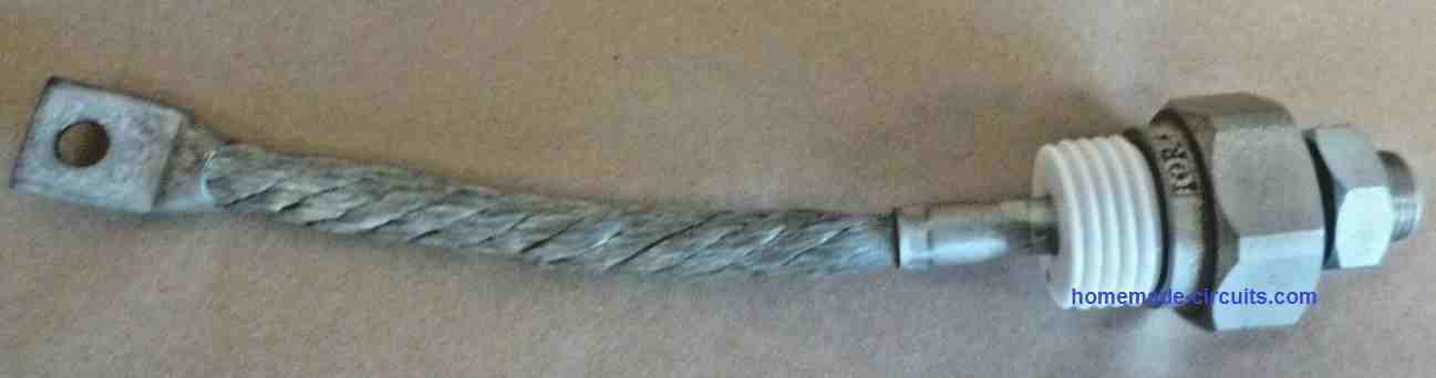
First change the 1N5408 diode position near the battery positive as shown in the updated diagram, because we want the battery voltage reaching the opamo preset all the time.
After this only for testing purpose, disconnect two things: First disconnect the 1N4148 link, then disconnect the LED 4k7 end from the transistor base and connect it directly to the ground line.
Now when you turn the 10K preset reverse/forward, the LED must also switch ON/OFF in response to this…so now you can set the preset such that at 14.6V the LED just switches ON. To confirm this result LED try reducing the 14.6V to 14.4V, and you will find the LED shutting off. This will prove your setting is correctly done. That’s all!!!
Now restore the 1N4148 and 4k7 connections back in their original positions, and connect a discharged battery to see it cutting off (LED ON) at 14.6V (14V at batt terminal)
Make sure that the battery Ah is 10 times higher than input current from the LM338 or LM317 IC whichever you have used.
As you said, the PCB worked perfectly well now the Led has to shut down or turn on before adding the battery
Because the LED is showing 8.2v on the current and 14.6v on turning off the LED
I did as you said but still not being autocut. Before connecting Betteri. Have to turn the LED on or
Off. tell me
LED On position Show 8.2v and LED off position show 14.6v
you must connect the battery first and then switch ON power. When you do this, the voltage will drop to the battery level, may be to 11V or 10.5V whatever may be the discharge level. Then slowly the battery will begin getting charged, and when 14V is reached across the battery terminals the red led will be ON, and the charging will be cut off.
okay. I will check and test.. thank u
Meaning 12v Battery will have to keep 3v or 5v more than 4k7 presets. Battery is 14.3V so you have to set 18v with 4k7 preset
initially do not connect any battery, feed 17V or 18V at the input, connect a meter across the LM338 output terminals, and adjust the 4k7 preset until a 14.6V is seen on the meter.
14.6V is mentioned because the diode at the battery positive would drop the 0.6V during actual charging, and provide only 14V across the battery terminals.
Please help me. My input is 17.5 V and 4K7 is set to 14.6 v from preset but not being autocut.
Keeping the 10k preset in the middle is being led on getting autocut but do not be autocut with Betterie, explain to me how autocut will be
I have explained the setting up procedure in the article, see the explanation under the PCB design…read it very carefully and do it as explained.
to do this
Set the 4k7 and 10k presets in such a way that the red led light is illuminated at 14.6v and then adding to the battery
first diconnet the 1N4148 link
then adjust the 10k preset to ground line
then switch ON input supply
then adjust the 4k7 to get 14.6V.
finally adjust the 10K preset such that the LED just switches ON.
After this you can connect the 1N4148 link back into postilion.
plz check circuit daigram: jmp.sh/O5pJiEu
zener 3.3v or 6v Not found in the market..It is replaced by 3.6v 0r 6.2v
There will not be any problem
And as you said adjust the 4k7 preset until a 14.6V is seen on the meter. So the same voltage for 7ah or 25ah bettery will be 14.6 v
Sorry Deepak due to lack of time I am not able to check the PCB tracks for accuracy, you will have to do it yourself.
yes the mentioned zener replacement will work.
14.6V is OK for all 12V batteries.
Input 17 vdc is given,
How much is the 4k7 preset set on voltage for 12v / 7ah battery
you will have to verify it using a digital multimeter
how to set preset 4k7 to 10k for 12v /7ah and 25ah bettery
you can replace the 4k7 preset with a 10K and use it as explained in the article
12v / 7ah to 25ah. You can use this circuit in betterie. Some changes need not be made in this circuit.
you can use any 12V battery upto 50 Ah., only the current limiter resistor will need to be modified as per the battery.
see the last diagram from the following article
https://www.homemade-circuits.com/lithium-polymer-battery-charger-circuit/
sir..Do not modify anything for me. You can tell me that you can charge up to 25ah betterie on this circuit with auto cut off
you can use it, but make sure not to use more than 4 amp transformer at the input…3 amp will be OK
thank you very much…Sir, how can I give you one thing and if you want to give some dollars in it. Do you have bitcoin wallet
it’s my pleasure If you are given a gift, how can it be given?
I appreciate your thoughts, however gift is not required…you can feel free to comment anytime you have any doubts or questions
thank you Deepak, You do not have to pay any fees for the help that I provide here, it is totally free.
Thank you very much Sir.It will give input 3amp only
sir . can use LM358 dip
yes, You can use any similar opamp
Sir.The resistor that is getting BC547 from LM338 out is 240 OHM/1W
It is 240 ohms 1/4 watt