In this post I have explained a simple low/normal battery voltage status indicator circuit through a flashing and a constant LED, where the flashing LED indicates a normal status while the solid indicator warns against a low battery condition. The idea was requested by Mr.Alf.
Technical Specifications
Hi, I found and built your “Low Battery Indicator Circuit Using Two Transistors Only”
On your website because I am growing vegetables in a raised bed and have erected 12v electric fence to prevent slugs and snails eating my plants.
for this I am using an old car battery which is holding a good charge.
The low battery indicator circuit is working fine but I have to put my meter across the terminals in order to check it is still working.
Is there any way to add a second LED that will flash to indicate power is there and working?
Thanks
Alf
The Design
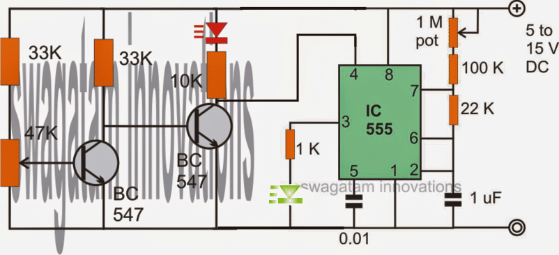
The figure below shows the circuit configuration of the proposed battery voltage status indicator circuit through a flashing LED indicator.
The left side stage which uses two BJTs is a simple low battery indicator circuit, the red LED lights up as soon as the supply voltage falls below the predetermined threshold level, as set up by the 47K preset.
This stage has been elaborately explained HERE, you may want to go through it for further details.
Low Battery Indicator with Astable LED
The low battery stage produces only a low voltage indication and the relevant LED shines only until the level dips below the set threshold, this might well keep the user guessing if the actual or the normal condition of the battery was OK and if the battery was functioning correctly in the meantime.
For satisfying the above results, a flashing LED indicator could be seen attached with the low battery section, using our old compatriot IC 555.
The IC 555 is wired in its conventional astable mode so that the connected green LED produces a flashing effect as long as its reset pin#4 stays above a certain positive voltage level via the red LED and the series 10k resistor.
Until the set lower threshold is not reached, the above pin of the IC is allowed to receive the specified amount of positive potential sustaining the green LED in a blinking mode, which in turn indicates that everything is well with the battery.
The moment the red LED starts glowing and gets illuminated sharply the green LED completely shuts down, making the conditions clear to the user regarding the battery which may be assumed to be fully down and gone below the dangerous low voltage mark.
The flashing rate of the 555 stage could be adjusted as per user preference by adjusting the 1M pot appropriately.
Solving the Low Supply Issue
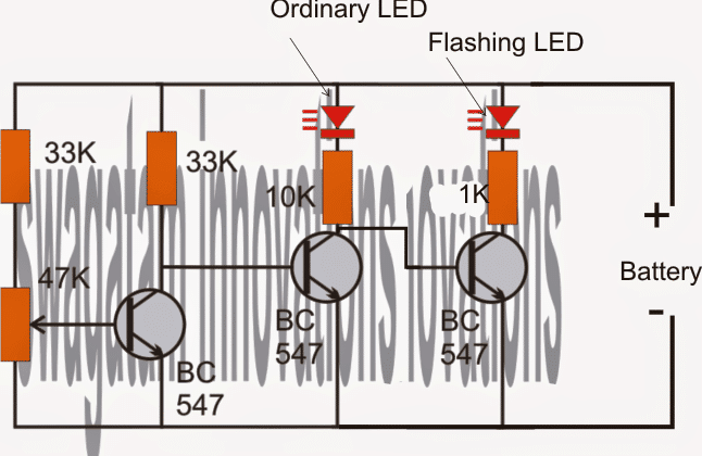
For lower voltage applications, the IC 555 stage may not function correctly since its minimum operating voltage is 4.5V, under such conditions the following configuration could be tried.
Here we find a third BJT being added to the existing stage, which holds a multicolor RGB flashing LED for the required indications (the same may be replaced with a simple LED if the flashing effect is not required).
The results obtained are identical, the left LED illuminates when a low voltage is detected, until this happens the flasher LED keeps blinking indicating a normal operation of the battery.
Improving the Circuit Outcome
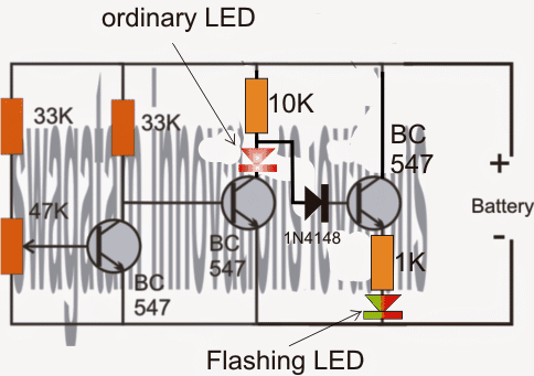
The above circuit has an issue and may not work as intended, because the left LED would be always ON due to the conduction via the right hand side BC547 emitter.
The following circuit corrects the above issue and may be used for implementing the proposed flashing LED battery status indication flawlessly.
Upgrading the Circuit with an Opamp
If a single LED is intended to be used for indicating the above effects, the following design may be tried. The idea is designed and explained by Mr. Abu-Hafss.
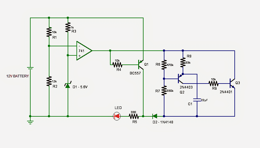
The circuit presented here features a single LED which:
Circuit Operation
a) when light up constantly would indicate the power has been switched ON and the battery charge level is good.
b) when flashes would indicate battery is low
The design is pretty straight forward, consisting of two parts. In the green part, op-amp 741 configured as comparator, along with its corresponding components compares the voltage with the reference voltage preset using a zener diode. If the voltage is higher than the threshold level, the output of 741 remains low which causes the PNP Q1 to conduct hence, the LED is powered on constantly.
As soon as the voltage level falls below the threshold level the output of 741 goes high. This causes the Q1 to stop conducting and the LED goes off. At the same time, the high output of 741 also switches on the flasher circuit in blue part (built around a pair of an NPN and a PNP transistor) which causes the same LED to flash. The flashing rate can be adjusted by varying the values of R8 and/or C1.
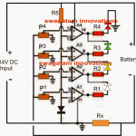
Alternatively, to make the flashing circuit more compact, this circuit may be tried.




Questions & Answers
I have been searching for a simple circuit that will start flashing led lights when I connect a transformer charger to the battery. Thanks sir
You mean to say the LED will flash as long as the battery is charging and become solid when it is fully charged?
Yes sir
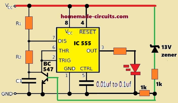
You can try the following circuit:
Hello sir am using a 24v inverter. Do u have a flashing led low battery indicator that can be used in a 24v battery and even with a relay?
Hello Morris,
you can try the last circuit from the above article, replace 741 with an op amp from LM358 IC. R2 can be replaced with a preset for the cut off adjustments.
You can add a relay between the collector of Q2 and battery negative.
Hello sir please can you help get a circuit that if battery is charging the LED will keep on blinking or flashing but when the battery get fully charged then the LED stop blinking and light up thank you hope to hear from you soon
Hi Daniel, you can try the following circuit, it will do exactly as mentioned in your requirement:
Just adjust the 10k preset such that at full battery charge pin#6 of the IC becomes high and locks the LED to a continuous illuminated state.
You can also try the following idea:
greetings swagatam,
in above high voltage glow and low voltage blinking circuit i am using transistor bc557 instead of 2n4403 and bc547 instead of 2n4401. the problem i got is both the time the LED is glowing. can you elaborate it. what mistake am i doing it.
thank you.
Hello prashant, in the last circuit the LED will blink only when the 741 output is high, so please check whether the output of 741 is getting high or not at the lower threshold.
Yes BC557 should also work, use BC547 for Q3
Hie swagatam,
As you told the circuit is getting high on lower threshold. but my problem is led is glowing while the power is passing through blinking circuit. so i want to know what mistake am i doing it. actually i cant find my mistakes so i want to know the possible mistake which i can do. please elaborate my possible mistake so i can understand and correct it.
Thank you
Hi Prashant, then it means your flasher circuit is not working. Please disconnect it from the 741 circuit and check it separately…the LED must blink, if it’s not blinking then you may have to check for the fault.
Hello,
Swagatam , here in the circuit i wanna use voltage regulator instead of zener diode. for reaching low voltage less than 2.7 v for blinking. will voltage regulator (AMS1117) work here ?
In that circuit i am removing R3 (1K) resistor.
kindly help me to reach my requirement for low voltage indication blinking LED and high voltage glowing LED circuit.
Thank you.
Hello swagatam,
As you told i have applied diode in circuit. the problem i am getting is 741 output is high but its 2.1 v. where as the blinking circuit is working with minimum 2.5v. so while i am reaching the 2.7 v input pin3 of 741. the LED is not getting sufficient voltage to blink. can you explain what changes required in blinking circuit?
Thank you,
prashant
Hello Prashant,
yes at 2.1V a 3V LED will struggle to glow properly, in that case you may have to use an external power for the LED.
Another issue is that, the IC 741 will not work at 2.7V either, I just forgot about this. So the entire circuit is not suitable for a 3V and lower supply.
The circuit will work only if we have a separate voltage for operating the 741 and the LED.
Hello Prashant, it will work, but you can achieve this simply by replacing the zener with 1N4148 diodes in reverse direction. One 1N4148 will allow you to get as low as 0.7V fixed voltage, two in series will give you 1.4V, and so on.
Thank you swagatam now that circuit is working nice.
again thanks to help me in circuiting.
Glad it’s working Prashant, keep up the good work!
Hi Swagatam,
Thank you for your fast answer. I will try this out soon.
I have a question regarding power supply.
I have built a touch sensitive circuit with a pot to adjust the sensitivity.
Connected to my lab power supply set to 12V it works very well. I can adjust the sensitivity so that I don’t need to touch the touch plate in order to make it react. Even at lower voltage (5V) it works well.
When I try the same circuit with 9V battery I have to touch the touch plate to make the circuit react.
My lab PSU shows that the circuit uses 10 mA
Can you explain me why?
Thank you in advance,
Henrik
Thanks Henrik,
Any mains operated power supply will have some ripple content in the line, may be this ripple content is making your circuit a little unstable, and which in turn could be causing it to be more prone to stray fields….whereas a battery voltage may be extremely constant with absolutely no ripple, and this could be allowing the circuit to be more stable and calm, and unresponsive to weak triggers….it's my interpretation, not sure whether it's correct or not.
Hi Swagatam,
Thank you for sharing all your circuits.
In my caravan I have added an extra 12V car battery to supply the caravan with power when not on a campsite.
Is there a way to show when the battery is being charged either by the car or a battery charger?
Best regards,
Henrik
Thanks Henriks, you can add a small value resistor in series with the battery positive, and add two LEDs in parallel to this resistor. Connect the LEDs with their polarities in the opposite directions, so that one LeD illuminates whenever the battery is charging and the other when the battery is being used by the load. you can put a diode in series with each LEDs to improve their polarity response
the values of the resistor could be calculated with the following formula
R = 3 x 10/battery AH
is there a way to make these circuits handle 18 volts input instead of 15 volts? thank you.
Keep up the good work
18V can be also used for the above circuits, except the IC 555 which will need a 7812 regulator at its pin8/4 for the a 12V regulated supply
can I swap the (24003 and 2n4001) for either (BC547 or BC556) or (BD140 or BD139) or a 555 timer?
please compare the datasheet values of the devices for getting the correct info….;look for the V, I specifications in the datasheet….
I build the above mentioned circuit having 2 led and 3 bc547 and connected a 12v battery but the problem is that the left led is always glowing and the flasher led only blinks when i adjust thr 47k preset. What mistake am i doing??
No, you can use 1N4007 or any other similar diode.
If i add a 12v zener diode in place of 1n4148 fiode will it work??
Thanks sir….
I will do the modification.
I have updated the corrected diagram, please do the shown modifications in your circuit accordingly.
OK, I understood the fault, the left LED is finding its conduction path through the flashing LED transistor's emitter.
I'll try to find a remedy for this and update the new diagram soon…please keep it pending until then.
Something's not correct in your circuit or in the adjustment procedure, first make the following design successfully, and then you can proceed with the flashing LED stage.
https://www.homemade-circuits.com/2013/05/low-battery-indicator-circuit-using-two.html
I have built a 0-12v regulated voltage supply with lm317 and 12v lead acid battery. When i apply 11v to the indicator circuit the left led is glowing constantly and adjusting the 47k prest has no effect on the led. I have replaced the flashing led with a normal led but its not glowing but after i adjust the 47k preset it glows but the left led als glows with it.
use a variable power supply instead of battery and apply 11V to the circuit, now adjust the 47K preset until the left LED glows brightly.
Now slowly increase the voltage to some higher point may be to 13V and see the response of the LEDs, you'll find the left LED shutting off and the right LED beginning to flash.