In this post I have explained how to build a simple laptop power bank circuit which can be used for charging a laptop battery during travelling or during outdoor trips.
This device can be specifically useful on situations or places where an AC mains outlet is unavailable or difficult to find.
Why Laptops Need a Battery
Just like mobile phones, laptops are also portable gadgets that require a battery to operate when there's no mains AC supply is available.
This is the main advantage of laptops over PCs since a laptop can be carried with us while travelling and can be operated from anywhere outdoors.
This becomes possible because a laptop has an in-built battery. The battery provides the required power supply to the device whenever needed, and allows the laptop to work without the need of an AC mains supply outlet.
Laptops are so portable and handy that these can be opened and operated by anybody on top of their laps, and hence the name laptop.
Which battery is used in Laptops
In most of the cases the preferred battery for a laptop is a Li-Ion battery.
Li-ion battery batteries are one of the most efficient types of batteries with a very high power-to-weight ratio.
Power-to-weight ratios signifies that the battery is capable of providing long backups at high power rates through relatively smaller light weight packages.
The voltage specifications of a laptop may vary for different laptops.
Some laptop may work with a 11.1 V battery some laptops may work with 14.8 V battery and some other types may work using batteries with higher voltage rating.
The average current rating of a laptop battery may be around 4000 mAh which can provide a backup power for a period of approximately 4 hours.
In this post I have explained how to build a laptop power bank circuit for a laptop using a 11.1 V Li-Ion battery.
The 11.1 V laptop battery uses 6nos of Li-Ion cells each rated at 3.7 V. The 6 cells are configured as 3S2P, meaning, two parallel sets of batteries each having 3 cells in series.
The mAh rating of each cell could be around 2000 mAh. Therefore two parallel sets would result in a total mAH rating of 4000 mAh.
Since there are 3nos of 3.7 V Li-ion cells are involved, the total voltage of the laptop battery becomes:
V = 3.7 + 3.7 + 3.7 = 11.1 V
This 11.1 V value is the level where the battery is at around fully discharged state.
Since the full charge value of each 3.7 V Li-Ion cell is 4.2V, the total value of a fully charged 11.1 V laptop battery would be:
V = 4.2 + 4.2 + 4.2 = 12.6 V
How to Build a Laptop Power Bank Circuit
The idea of the laptop power bank circuit is simple. We want to use a set of chargeable batteries in the power bank which has higher voltage specifications than the laptop battery.
This means, when the higher voltage from the power bank is connected with the laptop battery, the charge from the power bank battery starts transferring into the laptop battery. This continues until the laptop battery is fully charged and the power bank battery is discharged.
Since the laptop battery has 2 parallel sets of batteries with 3 series cells on each set, we will use a higher configuration of 4S2P. Meaning our power bank will have a 2 parallel sets of battery with each set having 4 cells in series.
With a configuration of 4 series cells, the total fully charged voltage of our power bank circuit will be:
V = 4.2 + 4.2 + 4.2 + 4.2 = 16.8 V.
Each cell can be rated 2000 mAh, which will allow the configuration to have a specification of 16.8 V 4000 mAh.
The complete connection diagram of the laptop power bank battery can be seen in the following figure:
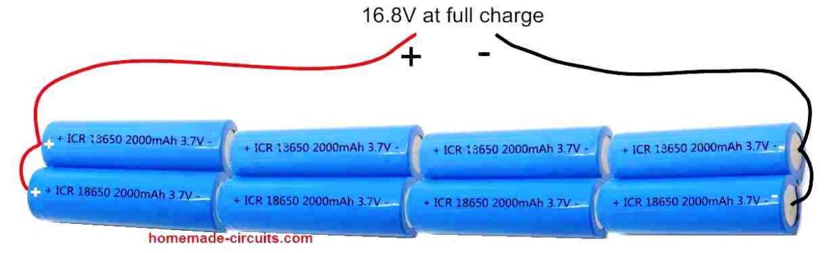
In the above figure we can see how a 4S2P (4 series, 2 parallel) combination of Li-Ion cells are configured to build a power battery pack of 16.8 V.
Specifications of each of the cells used in the battery pack are as follows:
- Li-Ion Cell = Type 18650
- Voltage = 3.7 V
- Capacity = 2000 mAh
Using Voltage Regulator
Although now we have an easy laptop power bank set up ready with us, the 16.8 V output is not safe to be directly applied to a laptop battery. Therefore, we need a voltage regulator that would regulate the 16.8 V into a constant 12.6 V.
For this we yet again rely on our work horse regulator IC LM338.
Using IC LM338 and a few other passive components we can build a very efficient, full fledged laptop power bank charger circuit, as shown in the following figure.
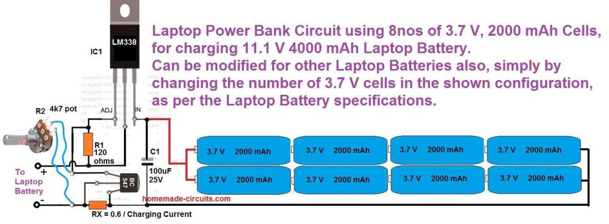
In the above design, the potentiometer R2 should be precisely adjusted to get 12.5 V at the output which can be then used for charging a laptop battery.
Although the full charge level of an 11.1 V laptop battery is 12.6 V we must adjust the output from the LM338 to precisely 12.5 V which is 0.1 V less than the full charge value.
This ensures that the laptop battery can never get over charged even if the power bank circuit is connected indefinitely with the laptop battery.
Calculating the Constant Current Resistor
Another aspect that Li-Ion batteries are typically critical about is the charging current which must be constant and limited. That's exactly why RX is positioned in the above shown LM338 circuit.
You will have to adjust the value so that it limits the current to a constant 0.5 C value which is equivalent to 50% of the laptop battery's mAh rating.
The value of the RX can be fixed using the following formula:
RX = 0.6 / 2 amp = 0.3 ohms
wattage = 0.6 x 2 = 1.2 watts or simply 2 watts
Make sure to apply a good heatsink on the IC LM338
The 0.6 V signifies the turn ON voltage of the BC547 transistor. When the current consumption tries to exceed the 2 amp value, it causes a voltage of 0.6 V to develop across the 0.3 ohm resistor which in turn causes the BC547 to switch ON. When the BC547 switches ON it shorts the ADJ pin of the LM338 to ground shutting it off. Shutting off LM338 at 2 amp consistently, prevents the charging current from exceeding the 2 amp mark.
How to Charge the Power Bank?
That's a valid question.
Before you can take the power bank unit with you for charging the laptop battery, you have to make sure the power bank battery is itself fully charged, otherwise it won't serve the purpose.
The idea is simple, construct another LM338 voltage regulator same as the one shown in the above image. However, since the power bank battery pack's full charge voltage level is 16.8 V, the output voltage from the LM338 regulator must be adjusted to a precise 16.7 V.
The complete circuit diagram for the power bank charger can be witnessed in the following figure.
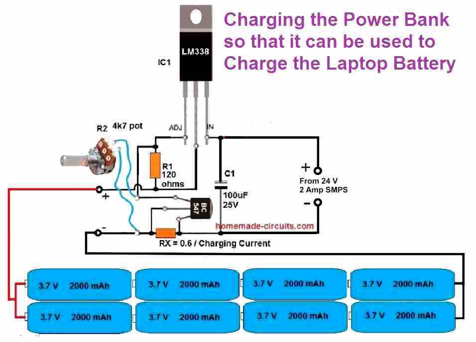
Again, here too we adjust the charging voltage 0.1 V less than the full charge level of the battery to make sure the battery pack never gets fully charged.
This concludes our article on how to build a laptop power bank circuit, if you any further questions please let me know through the below comment box, I will try to solve your queries ASAP.




Have a question or feedback? Feel free to ask below—just make sure it relates to the post above!