A circuit which allows a connected motor to operate in clockwise and anticlockwise directions through alternate input triggers is called a bidirectional controller circuit.
The first design below discusses a Full bridge or H bridge based Bidirectional motor controller circuit using the 4 opamps from the IC LM324. In the second article I have explained about a high torque bidirectional motor controller circuit using IC 556
Introduction
Generally, mechanical switches are accustomed to adjust the direction of rotation of a DC motor. Adjusting the polarity of the utilized voltage and the motor rotates the opposite direction!
On one hand this may have the drawback that a DPDT switch requires to be added to alter the polarity of the voltage, but we have deal with only a switch which makes the procedure quite easy.
However DPDT may have one serious issue, it is not recommended that you abruptly invert the voltage over a DC motor during its rotational motion. This may result in a current spike, which could possibly burn off the associated speed controller.
Furthermore, any kind of mechanical stress can also bring about similar issues. This circuit beats these complications easily. The direction and speed is manipulated with the help of a solitary potentiometer. Rotating the pot in a specified direction causes the motor to begin rotating.
Switching the pot in the opposite direction enables the motor to rotate in the reverse motion. The middle position on the pot switches OFF the motor, ensuring that the motor slows down first and then stops before an effort is made to change the direction is made .
Technical Specifications
Voltage: The circuit and motor make use of the common power supply. This implies that because the highest working voltage of the LM324 is 32VDC this likewise becomes the maximum voltage accessible to operate the motor.
Current: The IRFZ44 MOSFET is designed for 49A; the IRF4905 will be able to handle 74A. Nevertheless the PCB tracks that run from the MOSFET pins to the screw terminal block can just manage about 5A. This could be improved by soldering copper wire pieces over the PCB tracks.
In that case make sure that the MOSFETs do not become too hot - if they do then larger heatsinks will be needed to be mounted on these devices.
LM324 Pinouts

BIDIRECTIONAL CONTROL OF DC MOTORS USING LM324
Fundamentally, you will find 3 ways to adjust the speed of DC motors:
1. By using mechanized gears to attain the ideal acceleration: This approach is often over and above the convenience of the majority of enthusiast practicing in home workshops.
2. Decreasing the motor voltage through a series resistor. This can be certainly inefficient (power will be dissipated in resistor) and also result in the reduction in torque.
The current consumed by the motor also heightens as the load on the motor increases. Increased current means a more voltage drop over the series resistor and hence a dropped voltage for the motor.
The motor then makes an effort pull even higher amount of current, causing the motor to stall.
3. By applying the entire supply voltage to the motor in short pulses: This method gets rid of the series dropping effect. This is referred to as pulse width modulation (PWM) and is the strategy found in this circuit. Quick pulses allows the motor to operate slowly; extended pulses allow the motor run more rapidly.
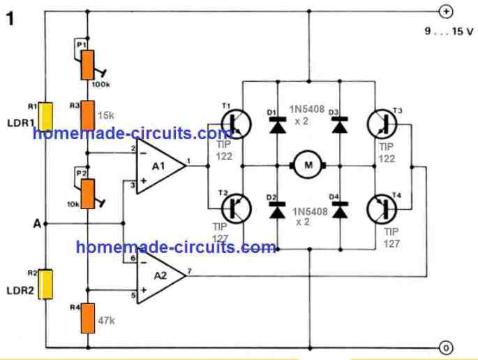
HOW IT FUNCTIONS (refer to schematic)
The circuit could be divided in four stages:
1. Motor control – IC1A
2. Triangle wave generator – IC1B
3. Voltage comparators – IC1C and D
4. Motor drive – Q3-6
Let us get started with the motor driver stage, centered around MOSFETs Q3-6. Only a couple of these MOSFETs remain in the activated state at any instant of time. While Q3 and Q6 are ON current moves through the motor and causes it to rotate in a single direction.
As soon as Q4 and Q5 are in operating condition the current circulation is reversed and the motor starts rotating in the opposite direction. IC1C and IC1D deal with which MOSFETs are switched on.
Opamps IC1C and IC1D are wired as voltage comparators. The reference voltage for these opamps are produced by the resistor voltage divider of R6, R7 and R8.
Observe that the reference voltage for IC1D is attached tothe ‘+’ input but for IC1C it is coupled to the ‘-‘ input.
This means IC1D is activated with a voltage higher than its reference whereas IC1C is prompted with a voltage lower than its reference. Opamp IC1B is configured as a triangle wave generator and supplies the activation signal to the relevant voltage comparators.
The frequency is roughly the inverse of the time constant of R5 and C1 – 270Hz for the values employed.
Decreasing R5 or C1 increases the frequency; increasing either of these is going to reduce the frequency.The peak-to-peak output level of the triangle wave is much less than the difference between the two voltage references.
It is therefore extremely hard for both comparators to be activated at the same time. Or else all 4 MOSFETs would begin conducting, leading to a short circuit and ruining all of them.
The triangle waveform is structured around a DC offset voltage. Increasing or decreasing the offset voltage varies the pulse position of the triangle wave appropriately.
Switching the triangle wave upward enables comparator IC1D to activate; decreasing it results in comparator IC1C to activate. When the voltage level of the triangle wave is in the middle of the two voltage references then none of the comparators are induced.The DC offset voltage is regulated by the potentiometer P1 via IC1:A, that is designed as a voltage follower.
This gives a low output impedance voltage source,allowing the DC offset voltage to be less vulnerable to the loading impact of IC1B.
As the ‘pot’ is switched the DC offset voltage begins varying, either up or down based on the direction the pot is flipped.Diode D3 presents reverse polarity safeguard for the controller.
Resistor R15 and capacitor C2 are a simple low pass filter. This is meant to clean any voltage spikes brought on by the MOSFETs as they turn ON supply power to the motor.
Parts List

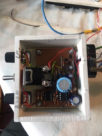
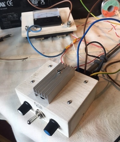
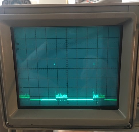
Prototype Images


Questions & Answers
Hi Swagatam. For my greater understanding of this circuit, can you please provide more detailed analysis of this circuit operation please. Especially cut-off values for the comparators & voltages at the oscillator (IC1b) pins for forward, reverse & neutral positions of the pot P1 please. Also example of relevant P1 values for these three states would be helpful. Thank you.
Hi Ballajurasic,
The circuit is fully explained in the above article…please go through and let me know what you did not understand…
Thanks for replying. As I mentioned in my comment – I would like to see worked examples that show potentiometer (P1) values for forward, stationary & reverse positions and the associated voltages at IC1B inputs as well as corresponding voltages at the comparators (IC1 C & D). Clearly my basic circuit analysis is failing me. Much appreciated if you can indulge me.
Thanks for this. My application is very different, controlling a bi-colour LED. This design has given me a way to do it.
I have an application where I would like to control a trolling motor with this type of circuit. The motors are driven by a 12v DC battery and the working Amps are 42 amps. It sounds like with some modification to the PCB this circuit you designed would work. What are your thoughts on what would need to change? Do you have a PCB file for this circuit?
I think it could be used for mentioned application. Sorry, I do not have the PCB design for this circuit.
There’s another circuit design which could be used for your purpose, you can check out the link below. The circuit can be found under the heading: Design#3: DC Motor Controller with Multiple Features
https://www.homemade-circuits.com/dc-motor-speed-controller-circuits/
For 42 amps the mosfets and the relay will need to upgraded accordingly.
Awesome thanks. For much support the curcuit works pretty good
My pleasure!
Please sir I want to used one of this circuit to control car kit BLDC motor, will it work?
BLDC are 3 phase motors, the above circuits are for brushed motors, not for BLDC
Como vai? gostaria, de mover um motor de aproximadamente de12v AC, com esse circuito seria possivel? obrigado.
Hi, Sorry AC motor cannot be controlled using the above concepts.
I’ve been working on a bidirectional dc motor circuit design to actuate a tiny dc worm drive motor that will operate the rudder on a multi engine radio control airplane design of mine. My idea has been to attach a vane to a potentiometer to sense airflow and from that signal, control my worm drive motor to position the aircraft rudder to control aircraft yaw when one engine is off. Your LM 324 circuit is definitely a step ahead of what I have envisioned. I had never considered pulse width modulation. I think that may solve my previous stumbling block of designing about a 1 or 2 degree dead zone on the yaw sense vane so the yaw actuator does not oscillate back and forth when the yaw is at the desired angle. (Usually 0 degrees). A 0 degree yaw provides the lowest drag and therefore the best one engine operation climb performance. I had also considered adding a pot controlled by a rudder servo that would likely somehow replace the R6, R7 and R8 resistor circuit so that I could control yaw angles and have more control of the airplane.
Could you provide ideas of resistance values for R1,R2 and P1 that would make the yaw sensor rather sensitive and a suggestion for the servo controlled yaw control?
The other addition that I don’t think would be to hard to design are limit switches for the rudder actuator motor and an airspeed switch to disable rudder positioning until the aircraft is up to flying speed.
An additional idea I’ve been considering is using two micro pressure sensors that would compare static pressure on the left and right side of a small vertical airfoil. The idea being that if the aircraft is not yawing the pressures would be equal but would differentiate in proportion to the aircraft yaw angle.. This would decrease the amount of moving parts (Reliability) and eliminate the need for an airspeed switch mentioned previously.
Thank You
Jim
for Mr. Jim Ransom.
Hello.ALL auto-pilot’s for a ‘yaw-control-line’ are based on vertical-supervisors (VS)!!!!! Simplest VS is a jointed to a potentiometer arm with a weight as a simplest kind of 3-pendulum’s VS. 1-st potentiometer’s pendulum’s arm is rotated = nose-aft. 2-nd= left-right wings. Both 1st and 2nd are vertical plane’s. 3-rd is for = horizontal rotation plane. All 3 planes potentiometer’s signals given to a analog/digital system (ADS) for calculating of a necessary rudder’s deflection angle. Than by a feedback potentiometers from rudder’s actuators the ADS can predict necessary deflection angle for a auto-pilot’s neegs = anti-turbulence function via very elaborated computations.
For you same – for a simplify – from the left-right potentiometer = P1 (100K of 1-st circuit) – direct to other elements of the 1st circuit but shell be a ‘zero-power to motor’ at +/- few degrees of angle of the potentiometer – against vibrations and a small oscillation influences.
I appreciate your ideas and sincerely hope they will work, but since I have no expertise in the aviation field or relevant mechanical operations, interpreting the system may not be possible for me.
However, as far as the first circuit is concerned, the adjustment of P1 will allow an equivalent amount of pulse width supply for the motor, meaning if the P1 is moved more towards the ground line, the motor will get reduced equivalent pulse width voltage and therefore will rotate slower, when P1 is moved towards the positive line, the pulse width will be wider causing the motor to rotate with higher equivalent speed.
In order to get a wider range you can simply remove R1 R2, which will allow the load to be operated from 0 to 100% power across the applied voltage range, depending on the P1 position.
Hi Swag,
Could you design a circuit for an electromagnetic bearing(Active magnetic Bearing) that can support large shaft with more than 500,000 RPM.
Sorry Hejazi, I have no idea about this circuit.
Swag,
I am looking for a circuit design for a motor control for a 110v outlet. The power is activated by a microswitch.
This would be for a 2 hp motor dust collector.
Here is a link for a similar system, this one is for 220v.
They used to make a 110v one but discontinued it and that is what I need. I could buy a wireless/remote control one but I like to have the hardwired control.
Is this something you can help me with?
Thank you.
Hi Paul,
I would recommend the 4) circuit from this article:
https://www.homemade-circuits.com/build-these-simple-flip-flop-circuits/
Just make sure the triac is a 30 amp 600 V rated
I am assuming that the input supply is from a 110V AC outlet
Halo swagatam, i want to make a mini wiper from dvd motor which running on lithium battery. can you give me a schematic diagram for it (if possible use transistor only)? Thank you and sorry for my english 🙂
Hello Uchi, you can try this
ok just ignor the acuracy . i need to just move a my 3kg blade by motor with aprox 6000rpm with higest torque . i am lil confuse of using moters.plese help me .and also for driver.
also suggest me 2 moter to drive a 50kg robot with speed.
understood, but still since 50 amp is huge a BLDC will work more efficiently, and will be very compact. Induction motors can be heavy huge and not so efficient.
swag.i want h bridge circuit whixh is capable of 50 amp with 12v to 36v with highly accurate and highly robust. i want this circuit for my robo war . and i also need your suggestion about wepon motor for robo war which i must buy . i want highest rpm with hightest torque. please suggest.
Hi Muhammad, if you are looking for high current and high accuracy system then you will have go for a BLDC 3 phase driver circuit, such as this one:
https://www.homemade-circuits.com/2017/08/high-current-sensorless-bldc-motor.html
Because 50 amp is huge a 3 phase motor will work better than a single phase system. Moreover it also includes a reverse forward facility and it works with sensorless motors.
For the motor also you can select a 50 amp 35V BLDC, all BLDC motors will offer excellent torque at high RPM