The post presents an 6v or 12v battery charger circuit for positive earth cars which could be used for upgrading 6V positive earth cars, facilitating an external 12V battery to be used in them along with the existing 6V battery with a common positive earth body. The idea was requested by Mr. Joe Ceretti.
6V to 12V Converter for Positive Ground Car
I have been looking at many of the wonderful circuits on your blog. I have a question, but first some information.Many people with antique cars could use a special charger. Basically, these old cars have generators that charge a 6 volt lead acid battery by supplying between 6.8 - 7.1 volts / 26-36 amps to the 6v battery while the car is running. Many people want to add a second 12 volt lead acid battery to power modern accessories.How easy would it be to design a circuit that would allow the generator to continue charging the existing 6 volt battery and would also charge the second 12 volt battery? Further details.The existing systems in these cars use a 6v positive ground system and the second battery would be 12v negative ground.Both batteries would need to be grounded at the same time to the common car chassis.There are many thousands of people out there whom would be very happy to have access to this type of charger.Sincerely, Joe Ceretti
Circuit Diagram
The Design
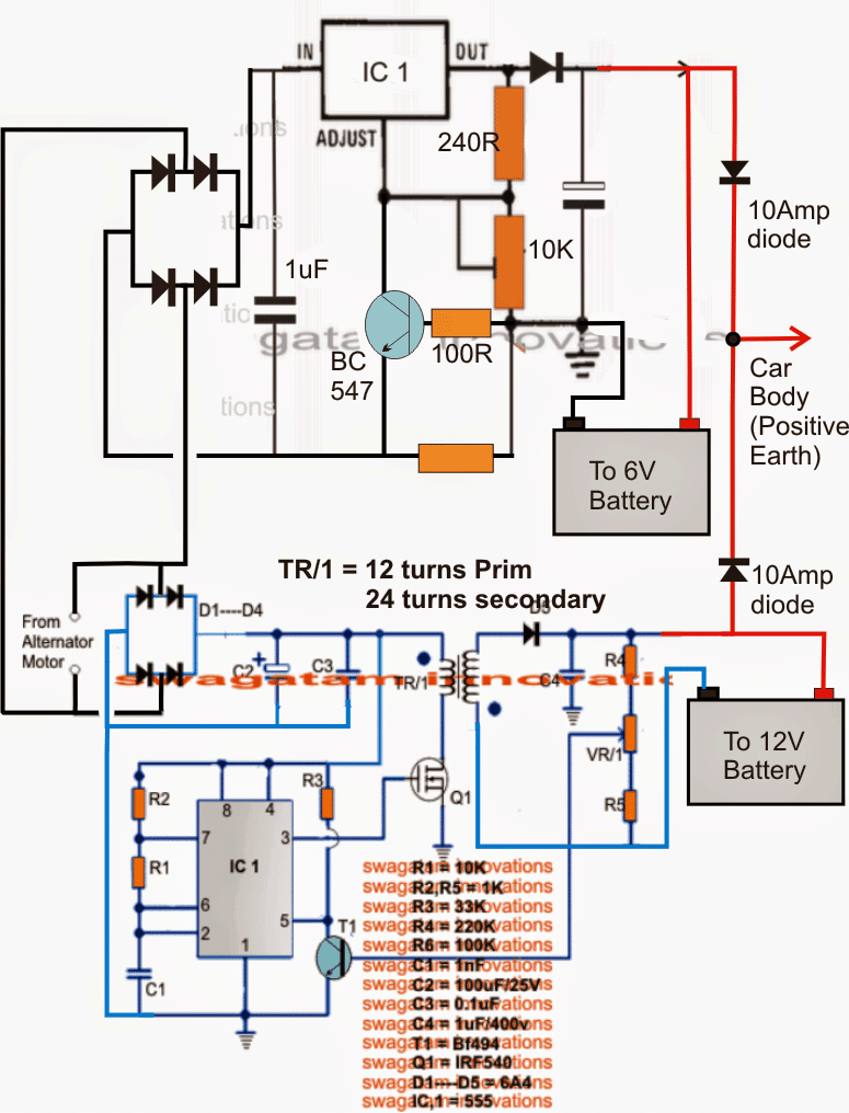
The diagram of the proposed 6V and 12V battery charger circuit for positive earth cars shows two separate stages consisting of one LM396 variable voltage regulator stage and another 555 IC based 6V to 12V boost converter stage.
The upper LN396 stage is configured to produce a variable output range of 1.25V to max depending on the alternator voltage supply capacity, while the lower boost converter is positioned to upgrade the 7V AC from the alternator to the required 14V for charging an optional12V battery.
The 10K preset in the LM396 circuit could be adjusted for achieving a constant 7V for the connected 6V battery. The resistor presented in between the base and emitter of the attached BC547 transistor functions as the current limiter. The value may be selected as per the formula: R = 0.6 x 10/Battery AH.
The 555 IC boost circuit is responsible for boosting the 7V from the alternator to the required levels for charging the connected 12V battery.
The preset VR1 may be fine tweaked for getting the exact 14V across the battery.
Coil Details
The coil TR1 may be wound as follows:
Core: 1 inch OD
Primary: 12 turns using 1mm magnet wire
Secondary: 24 turns using 1mm magnet wire


Questions & Answers
Dear sir
I will post a question here since this is the only thread regarding antique vehicles with positive earth.
Our cars use the traditional 3 coil mechanical voltage regulators consisting of voltage, current and cut off coils. Generators are 30Amp two brush shunt type with one brush grounded. Field is shunted across armature.
When desired voltage is reached at A (armature) current regulator controls field.
What puzzles me is no vendor is selling solid state regulators for these. Only 20Amps are available.
If this is not possible to construct, what about some kind of filter to clean output of mechanical regulators. I’m concerned over using AGM battery.
Lastly there is a market for these solid state regulators as interest for antique/classic cars is on the rise.
Hello Morrice, I guess you are referring to solid state car alternator regulators. I have a related post on this, you can find it in the following link:
https://www.homemade-circuits.com/car-alternator-regulator-circuit/
Thank you for swift answer.
I skipped the page during search. Title is regarding alternators.
Mine is a DC generator (Dynamo with commutator)
First diagram is for grounded field. Mine has Field is shunted across armature.
Third diagram is for an AC Alternator with tacho connection.
Diagram 2 looks more suitable but D3 20A Diode is too low for a 30A generator. Also, TIP36 collector current is also only 20A. After reading the explanation from Chrysler Corporation regarding the Zener’s function, it’s obviously constructed for an Alternator.
What I (and others) need, is a 6v positive ground DC generator solid state regulator.
Please enlighten me if I have misunderstood it.
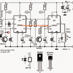
In that case you can probably modify the following concept to obtain a shunt regulator circuit: