• Skip to main content
  • Skip to primary sidebar

Homemade Circuit Projects

Need circuit help? Post them in the comments! I've answered over 50,000!

Blog | Categories | About | Hire Me | Contact | Calculators-online
You are here: Home / Battery Charger Circuits / 3.7 V Li-Ion Battery Charger Circuit with Automatic Cut-off

3.7 V Li-Ion Battery Charger Circuit with Automatic Cut-off

Last Updated on May 17, 2026 by Swagatam 403 Comments

In this article we study a simple 3.7V li-ion battery charger circuit with auto-cut off, which can be charged from your computer USB port or any other 5 V regulated source.

Table of Contents
  • Simplest 3.7V Li-ion Battery Charger with Auto Cut-off using LM393 IC
    • How it Works
    • How The Whole Circuit Works Step By Step
      • Power Source And Battery Connection
      • Voltage Divider For Sensing Battery Level
      • Reference Voltage From Zener Diode
      • Comparator Working Principle
    • Case 1: Battery Voltage Is Low Or Discharged (below 4V or 4.1V)
    • Case 2: Battery Voltage Is Full (4.1V Or 4.2V)
    • Role Of The 2.2k Resistor
    • Step By Step Summary Table
    • Main Points To Remember
    • Summary Of The Operation
    • How to Set up
    • Constant Current Version
    • 3.7V Auto Cut-off Circuit using IC 741
    • How to Charge using USB Port
    • How to Set up the above 3.7 V Li-ion Charger Circuit:
    • Constant Current CC Feature Added
      • Current Limiting not Required for USB Power
    • Improving the Circuit Further
  • Adding Current Control to the above Design
    • Using a 5V Relay
    • Another Ideal 3.7 V Battery Charger Circuit with Auto Cut-off
    • How to Adjust the Preset

Simplest 3.7V Li-ion Battery Charger with Auto Cut-off using LM393 IC

If you do not wish to read the following long explanation, you can just watch the same in this video:

How it Works

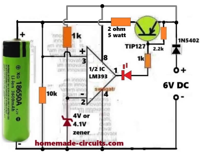
Here we see that this small circuit is made for charging one 3.7V Li-Ion cell like 18650 type, and we also see that it automatically stops the charging when the cell voltage becomes full around 4.1V or 4.2V.

So we can say that this is an automatic over charge protector using one half section of LM393 and one PNP transistor TIP127 which is working like a main current switch.

How The Whole Circuit Works Step By Step

Power Source And Battery Connection

We start by giving 6V DC supply to the circuit which acts like the charging input. The 3.7V battery is connected on the left side, so that the current flows from 6V supply through the TIP127 transistor to the battery for charging purpose.

Voltage Divider For Sensing Battery Level

The pin#3 of the LM393 is connected directly to the battery positive so it can sense the battery volatge level directly. So this way pin3 can sense the present battery level.

Reference Voltage From Zener Diode

We have one 4V or 4.1V zener diode connected to the inverting input pin2 of LM393. That zener is giving a fixed reference voltage which stays constant even if the battery voltage changes. So we can say that pin2 is having fixed 4.1V reference while pin3 is showing actual battery sample voltage.

Comparator Working Principle

Now we understand that LM393 is acting like one comparator, so it is comparing the voltages present at pin3 and pin2.

Case 1: Battery Voltage Is Low Or Discharged (below 4V or 4.1V)

So now that battery voltage is less than 4.1V, so voltage at pin3 is lower than voltage at pin2. Then the LM393 output transistor from inside becomes ON and it pulls pin1 to ground.

Because of this, pin1 becomes low and that low goes to the base of TIP127 through one 1k resistor. Since TIP127 is a PNP transistor, so its base getting low will make it conduct hard, so the current now starts flowing from emitter to collector and reaches the battery and the battery begins to get charged.

The LED also turns ON in this time because its cathode at pin1 goes to ground.

So we can now say in this condition:
LM393 output = LOW (Ground).
TIP127 = ON.
LED = ON.
Battery = Charging.

Case 2: Battery Voltage Is Full (4.1V Or 4.2V)

Now after sometime the battery gets almost charged, so that the voltage at pin3 becomes slightly higher than pin2. Then in this situation the internal transistor of LM393 turns OFF and its pin1 becomes open collector, that means pin#1 is now floating, without any logic level (open).

Now since pin1 is open, it cannot pull low anymore, so in this situation the 2.2k resistor now becomes active. That 2.2k resistor is connected from +6V to TIP127 base node so it pulls the base of TIP127 towards positive potential.

So when the base is pulled high and becomes near the emitter voltage, forces the TIP127 hard to stop conducting completely. So current cannot flow anymore from emitter to collector. The battery is disconnected from the charger. The LED also turns OFF because now there is no current path to ground through pin1.

So we can say now:
LM393 output = OPEN.
TIP127 = OFF.
LED = OFF.
Battery = Cut Off.

Role Of The 2.2k Resistor

Now we explain that 2.2k resistor which is very important here. It is actually working like a pull-up resistor, so that resistor is keeping the TIP127 base in one correct position depending on the output of LM393.

So when LM393 output is low, then that resistor becomes inactive because LM393 is grounding the base through the 1k resistor. So charging goes ON.

But when LM393 output is open then that 2.2k resistor pulls the TIP127 base high towards the emitter potential. So the transistor gets turned OFF strongly and it cannot conduct any leakage current. So this resistor ensures that the base never floats and the transistor never stays in half ON condition.

If that resistor is not there then the base of TIP127 may stay floating after LM393 goes open and this may allow some small leakage current to flow continuously, and the battery may keep trickle charging which is unsafe for Li-ion cell. So this 2.2k resistor saves the battery from such leakage problem.

Step By Step Summary Table

Battery ConditionPin3 Vs Pin2LM393 OutputRole Of 2.2kTIP127LEDBattery
Low Or DischargedPin3 < Pin2Pin1 = GroundInactiveONONCharging
Fully ChargedPin3 > Pin2Pin1 = OpenActiveOFFOFFCut Off

Main Points To Remember

So we now understand that LM393 works as one precise voltage comparator. The 4.1V zener sets the final cut-off limit. TIP127 handles the charging current. The LED gives visual indication of the charging status. The 2.2k resistor ensures proper base pull-up. And the diode 1N5402 stops the reverse current flow from battery to the circuit whenever the charger is unplugged.

Summary Of The Operation

We can now say everything in one line like this:

When the battery is below 4.1V then the LM393 output becomes low, then the TIP127 conducts, then the battery charges and LED glows. When the battery becomes full near 4.1V or 4.2V then the LM393 output becomes open, then the TIP127 stops conducting, then charging stops, and LED goes OFF.

So it works fully automatic and safe for 3.7V Li-ion cells.

How to Set up

It is actually very Easy.

During the setup procedure, do not connect any battery, instead, connect a variable power supply DC input on the battery side, meaning replace the battery points with this variable power supply DC input.
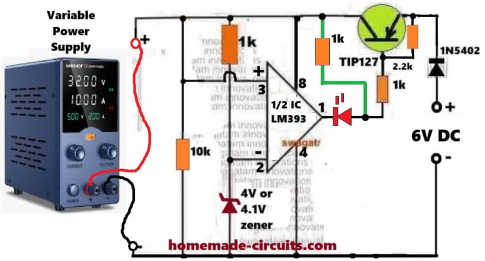
Connect a 1k temporary resistor between pin#8 of the IC and the anode of the red LED.

Keep the supply at zero volts and gradually increase it, until it reaches above 4.1V, or 4V.

At around 3V, you must see the LED turning ON.

Keep increasing the variable power supply voltage until it is above 4V or 4.1V. At this point you must see the LED shutting off.

That's all, this will prove that you LM393 based auto cut off is working correctly.

Now you can remove the above mentioned temporary resistor, and start charging any discharged 3.7V Li-ion battery using the normal configuration, as depicted in the above image.

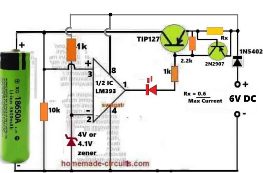
Constant Current Version

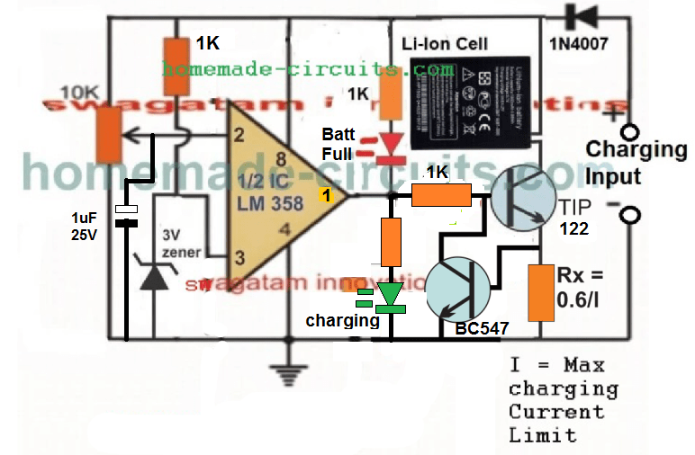
The above circuit can be further upgraded into a constant current version, as shown in the following diagram:
3.7V Auto Cut-off Circuit using IC 741

The following IC 741 auto cut off Li-ion battery charger circuit can be understood with the help of the following description:

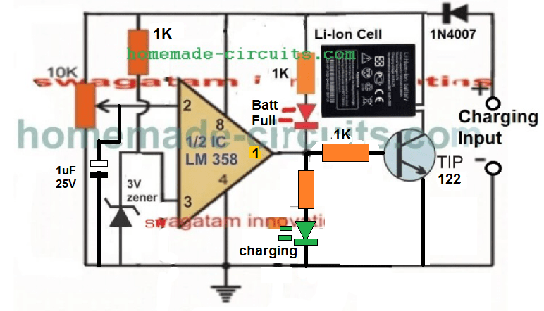
The IC LM358 is configured as a comparator. The IC LM741 is not used since it is not specified to work with voltages lower than 4.5V.

Pin#2 which is the inverting input of the IC is used as the sensing pin and is attached with a preset for the required adjustments and setting.

Pin#3 which is the non-inverting input of the opamps is reference at 3V by clamping it with a 3V zener diode.

A couple of LEDs can be seen wired across the output pin of the opamp, for detecting and indicating the charging condition of the circuit. Green LED indicates the battery is being charged while the red illuminates as soon as the battery is fully charged, and supply is cut off to the battery.

How to Charge using USB Port

Please remember that the charging process can be quite slow and may take many hours, because the current from USB of a computer is normally very low and may range between 200 mA to 500 mA depending on which number port is used for the purpose.

Once the circuit is assembled and set up, the below shown design can be used for charging any spare Li-Ion Battery through the USB port.

First connect the battery across the indicated points, and then plug in the USB connector with your computer's USB socket. The green LED should instant become ON indicating the battery is being charged.

You can attach a voltmeter across the battery to monitor its charging, and check whether the circuit cuts off the supply correctly or not at the specified limit.
USB 3.7V Li-Ion Battery Charger Circuit

Since the current from a computer USB can be quite less, the current control stage can be ignored and the above design can be much simplified as shown below:
Video Clip showing the automatic cut off action, when the Li-Ion cell is charged upto 4.11V:

Please note that the circuit will not initiate charging unless a battery is connected prior to power switch ON, therefore please connect the battery first before connecting it to a 5 V supply source.

An LM358 has two opamps which means one opamp is wasted here and remains unused, therefore LM321 may be tried instead to avoid the presence of an idle unused opamp.

How to Set up the above 3.7 V Li-ion Charger Circuit:

That's extremely easy to implement.

  1. First, make sure the preset is moved at the ground side fully. Meaning, the pin#2 should be at ground level through the preset initially.
  2. Next, without any battery connected, apply an exact 4.2 V across the +/- supply lines of the circuit, through an accurate adjustable power supply.
  3. You will see the green LED coming ON instantly.
  4. Now, slowly rotate the preset, until the green LED just shuts OFF, and the RED LED switches ON.
  5. That's all! The circuit is now all set to cut off at 4.2 V when the actual Li-Ion cell reaches this level.
  6. For the final testing, connect a discharged battery to the shown position, plug-in the input power through a 5 V source, and have fun watching the cell getting charged and cut-off at the stipulated 4.2 V threshold.

Constant Current CC Feature Added

As can be seen , a constant current feature has been added by integrating the BC547 stage with base of the main BJT.

Here the Rx resistor determines the current sensing resistor, and in case the maximum current limit is reached, the potential drop developed across this resistor quickly triggers the BC547, which grounds the base of the driver BJT, shutting down its conduction and charging of the battery.

Now, this action keeps oscillating at the current limit threshold, enabling the required constant current, CC controlled charging for the connected Li-ion battery.

Current Limiting not Required for USB Power

Although a current limiting facility is shown, this may not be required when the circuit is used with an USB since the USB already is quite low with current and adding a limiter may be useless.

The current limiter should be used only when the source current is substantially high, such as from a solar anel or from another battery

Improving the Circuit Further

After some testing it appeared that the Darlington transistor was unable to switch sufficient current to a Li-Ion cells, especially which were deeply discharged. This resulted in a difference in voltage levels across the cell, and across the supply rails of the circuit.

To combat this issue, I tried to improve the design further, by replacing the single Darlington BJT with a pair of NPN/PNP network, as given below:
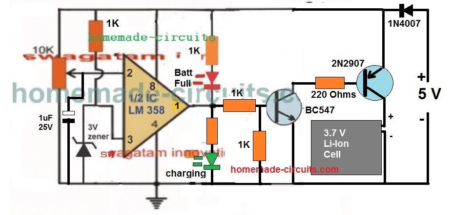
This design improved the current delivery significantly, and resulted in a reduction in the margin of difference between the battery terminal voltage level and the actual supply voltage level, and therefore false cut-off switching.

The following video, shows the test result using the above circuit:

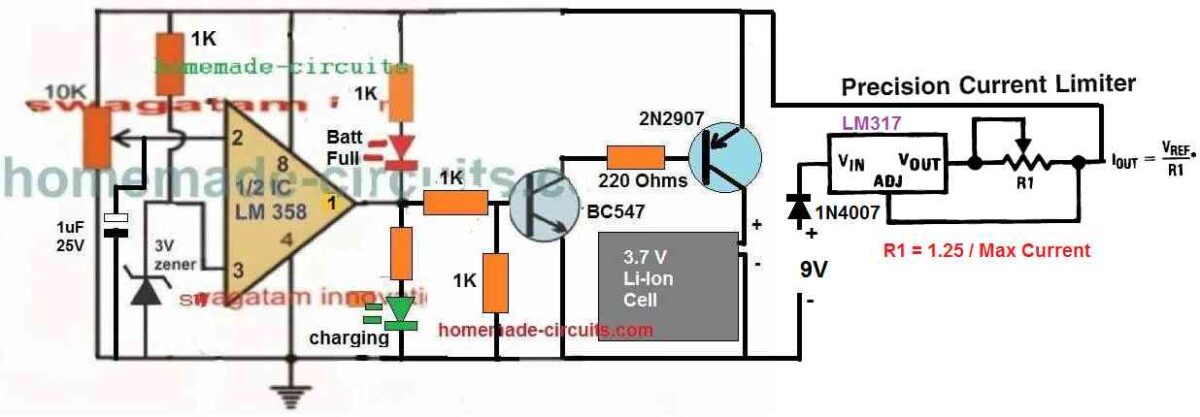
Adding Current Control to the above Design
Using a 5V Relay

The above designs can be also built using a 5V, which will ensure the best possible current delivery to the cell and faster charging. The circuit diagram can be seen below:
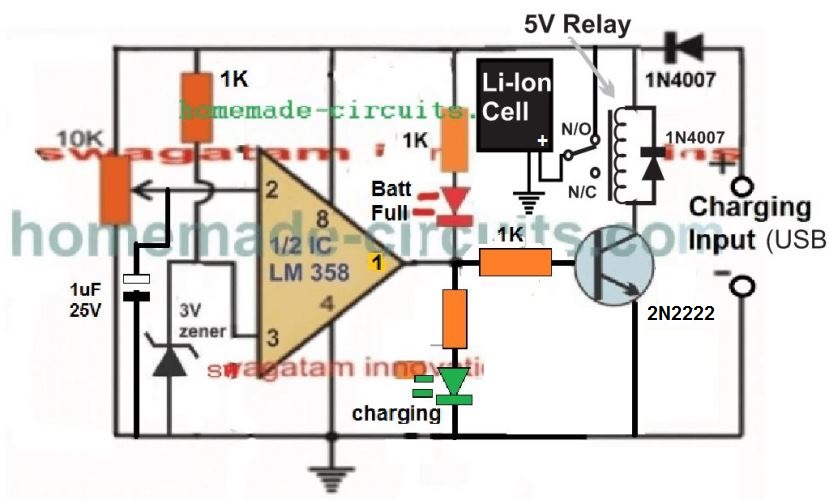
5V relay Li-ion charger circuit

Please Note: 

This article was substantially changed recently and therefore the older comment discussions may not match with the circuit diagram shown in this present updated design and explanation.

Another Ideal 3.7 V Battery Charger Circuit with Auto Cut-off

Here's a 3.7 V Battery charger circuit which looks perfect in for the automatic cut-off and a self-monitoring of the 3.7 V battery.
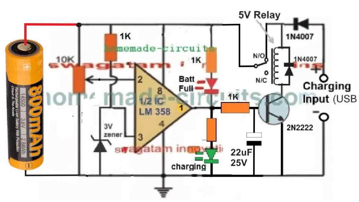
In the relay based circuit previous to the above design, there seems to a serious drawback.

In the previous design the battery needs to be connected first, before applying the input power. This is crucial, otherwise the relay can start chattering, if the power is switched ON first without a battery connected.

But in the above new design where the battery can be seen connected on the left side, the chattering of relay problem is completely eliminated.

Moreover, this design has an added advantage. The circuit will be able to continuously monitor the battery level and self-regulate the circuit to ensure that the battery is automatically disconnected when it reaches full charge level, and automatically connected to the supply when it is discharged to some lower level.

The input supply can can be from any 5V regulated source. However make sure the current spec of the supply is restricted to 0.5 C. Meaning the current of the 5V source must not be 50% of the battery mAh value.

How to Adjust the Preset

The auto cut off preset setting up is easy.

Initially, do not connect any battery or the input supply, and rotate the preset wiper to the ground level.

Next, take a variable DC power supply. Adjust its output to precisely 4.1 V, which is the optimum full charge level of a standard 3.7 V battery.

Connect this supply to the circuit from the left side, across the points where the battery is supposed to be connected.

You will see the GREEN LED illuminating. At this stage the relay must switch ON, however it won't since there's no 5V supply from the right side of the circuit. No worries, we can still setup the circuit by looking at the LEDs.

After this, slowly adjust the preset until the GREEN LED just switches off and the RED LED just switches ON.

That's all, the auto cut off set up is complete for the circuit.

Now, to test the circuit LIVE, you can connect a discharged 3.7V cell across the indicated points, and a 5 V supply from the relay side and see the actually cut-off happening, as soon as the battery is fully charged at 4.1 V.

You'll also like:

  • NiCd battery compressedTypes of Batteries Explained [NiCd, NiMH, Lead Acid, Li-Ion]
  • solarmpptchargercircuitSelf Optimizing Solar Battery Charger Circuit
  • chargingbatteryfromsmpssolarchargercircuit.Convert SMPS into a Solar Charger
  • Make this EV Battery Charger Circuit

Filed Under: Battery Charger Circuits Tagged With: Automatic, Battery, Charger

About Swagatam

I am an electronics engineer and doing practical hands-on work from more than 15 years now. Building real circuits, testing them and also making PCB layouts by myself. I really love doing all these things like inventing something new, designing electronics and also helping other people like hobby guys who want to make their own cool circuits at home.

And that is the main reason why I started this website homemade-circuits.com, to share different types of circuit ideas..

If you are having any kind of doubt or question related to circuits then just write down your question in the comment box below, I am like always checking, so I guarantee I will reply you for sure!


Previous Post: « Vehicle Speed Limit Alarm Circuit
Next Post: Footstep Activated LED Trouser Light Circuit »

Reader Interactions

Questions & Answers

Total Posts: 403
Newest Oldest
Hewey
January 26, 2026 • 7 months ago #199657

The 118650 battery charger is voltage-controlled, NOT current-controlled. I question the validity of the entire article due to this simple, but crucial and important mistake.

Reply
Vv
May 27, 2026 • 3 months ago #207580

if the 1k resistor connect to the + of battery like the circuits in video then diozener will change Voltage depend on the voltage of battery so the charging progress will stop sooner than theoricality.

Reply
SwagatamAdmin
May 27, 2026 • 3 months ago #207587

The issue has been already addressed long back in the video comment section, and the comment pinned on top.
The correct circuit versions are given in the above article.
The ideal version is to use a preset for the over charge cut off threshold and a zener as the reference source, but since I wanted to avoid the preset adjustment hassles, I came up with these plug and play, preset less concepts.

Reply
SwagatamAdmin
January 26, 2026 • 7 months ago #199666

Please explain your point, I will let you know where you are going wrong…

Reply
Moe
October 8, 2025 • 11 months ago #187895

Dear Sir Swagatam
Hello, it is my duty to thank you for your kind assistance and the time you dedicated to responding to me and redrawing the circuits.
Your kindness is always present before my eyes.
I am 100% sure that the circuit is perfect and the semiconductors are indeed faulty.
God bless you
With warmest regards,#
Moe

Reply
SwagatamAdmin
October 14, 2025 • 10 months ago #188266

Hello, Dear Moe,
I am extremely sorry and I admit that the previous circuit which I suggested you had a big problem and i am extremely sorry about all the hassles you had to face while testing the circuit.
I really don’t know how I missed this basic issue in the design.
In the previous circuit the 4V zener diode was linked with the battery, so how could the pin#2 of the LM393 get a fixed reference of 4V if the battery voltage was below 4V, so the IC could never do the comparison, and that’s why it kept failing.
The 4V zener resistor side must be connected directly with the input supply DC, and not with the battery so that pin#2 is able to get a fix reference, which could be compared with the battery voltage.

If you have time in near future then you can check this updated circuit and see if it works or not:
current controlled 3.7V li ion auto cut off charger circuit
Again, I am extremely sorry about all the trouble you had to face with the previous faulty design, due to my silly mistake…

Reply
SwagatamAdmin
October 8, 2025 • 11 months ago #187899

It is my great pleasure Dear Moe, thank you so much for your kind words!!
God bless you too!!

Reply
Ali
September 24, 2025 • 11 months ago #186337

Dear Sir engineer Swagatham
Hello
would you please tell me how much is the amount of the resistor which is connected to the positive pole of the green LDR? 1k?
Truly yours
Ali

Reply
SwagatamAdmin
September 24, 2025 • 11 months ago #186343

Hi Ali, yes both the LED resistors are 1k.

Reply
Nitesh Agrawal
March 27, 2025 • 1 year ago #170586

Dear Sir

which N channel MOS i will choose. does it logic level or which is best?

Reply
SwagatamAdmin
March 27, 2025 • 1 year ago #170601

Nitesh,
yes a logic level MOSFET would be better, such as this one:
https://www.digikey.com/en/products/detail/vishay-siliconix/IRLZ44STRRPBF/856860

Reply
Nitesh Agrawal
March 28, 2025 • 1 year ago #170652

Thanks

Reply
Nitesh Agrawal
March 27, 2025 • 1 year ago #170580

Dear Sir
i want to pass Power Bank 5V@9000 maH voltage to mobile device via Mosfet & gate of that mosfet is connected with mcu ( for on / off) . I am find out best method how can mcu &mosfet connetion each other May i ground one resistor also from Mosfet Gate ? there is facilities inside software for do logic high or logic low for mosfet operate at the time on timer & off timer.so pl give schamatics.

Reply
SwagatamAdmin
March 27, 2025 • 1 year ago #170585

Hi Nitesh,
You can configure the circuit in the following manner:
Connect the N-channel MOSFET gate directly with the MCU output. No need of any pull down resistor.
Connect the source with the ground line of the MCU.
Connect +5V of the power bank with MCU (+) and connect the negative of the power bank supply with the MCU ground.
Connect this +5V also with the mobile charging input (+) and connect the mobile ground with the drain of the MOSFET.

Reply
Anto Das8
November 3, 2024 • 2 years ago #164853

What can be the substitute for the 150E resistor in the project in the link
3.7V auto cut off battery charger circuit

Reply
SwagatamAdmin
November 3, 2024 • 2 years ago #164854

There is no substitute for this resistor, you can make it by adding a few assorted resistors in series parallel, slight difference is OK…

Reply
Anto Das8
October 31, 2024 • 2 years ago #164737

Which circuit (in your opinion) is best in factors like time taken for charging, safety

Reply
SwagatamAdmin
October 31, 2024 • 2 years ago #164738

The following circuit is the best:
3.7V auto cut off battery charger circuit

Reply
Anto Das8
October 31, 2024 • 2 years ago #164734

Can we use a 1.67A Samsung adaptor

Reply
SwagatamAdmin
October 31, 2024 • 2 years ago #164735

Yes, definitely you can use it…

Reply
Nelio
July 8, 2024 • 2 years ago #153950

Hi,
Does these circuits only work in fully empty batteries, 0V?
I assembed the 3rd circuit, for the 4th time, calibrated, with the preset at ground level (0homs), turn it on, green LED was on, move the preset until red LED becomes on, turning OFF green LED.
Connected a battery with only 2.3V, plug it to a 5V DC adapter and the red LED came ON, implying that the battery was charged….

Reply
SwagatamAdmin
July 9, 2024 • 2 years ago #154029

Hi,
The circuit can be used to charge any 3.7V battery discharged below the set level (4.1V).
While setting up the preset, the supply input to the IC must be exactly adjusted at 4.1V.
I hope you have connected 1uF at pin#2.
Also, the input power supply current must be rated at 50% of the battery Ah.
If you are having difficulty setting up this circuit you can try the following one:
3.7V auto cut off battery charger circuit

Reply
Nelio
July 8, 2024 • 2 years ago #153938

Hi,
When you say preset to the ground, means that the resistor value between the center point and ground is 0 (zero).
Right?
If that is so, meassuring between the entry point of the adjustable resistor and the center point is about 3K, leaving 7K between the center point and ground.
Nélio Abreu

Reply
SwagatamAdmin
July 8, 2024 • 2 years ago #153941

Hi Nelio,
Yes, that refers to resistance value between the center point and ground, which should be 0 (zero).
This is to be done during the setting up procedures of the preset. initially we must keep the preset fully towards ground and then slowly adjust it until the LEDs just changeover. This sets up the op-amp cut-off threshold.
There’s no need to measure the preset resistance, you can confirm the changeover through a variable power supply voltage and LED switching.

Reply
Nelio Abreu
June 1, 2024 • 2 years ago #152637

Hi, Swagatam,
I’m currently testing the 2nd circuit, with 2 minor changes:
Using TIP41C and without the base resistor and so far is working fine.
The 3rd circuit didn’t work
Best Regards.
Nélio

Reply
SwagatamAdmin
June 2, 2024 • 2 years ago #152640

Hi Nelio,
A base resistor is strictly recommended for all BJTs, so please do not remove the base resistor.
The 3rd circuit should work, because it has been tested by me, you can see the adjoining video.
However, here’s another design which is very basic and very good, and virtually failproof, you can try it:
3.7V auto cut off battery charger circuit

Reply
Nelio
July 10, 2024 • 2 years ago #154157

Hi, the LED in the failproof circuit, is what? Charging LED or Charged LED?
How to I set the trimmer?
Best Regards.
Nélio

Reply
SwagatamAdmin
July 10, 2024 • 2 years ago #154159

That LED indicates the battery is Charging, when it is shut-off means battery is fully charged.
To ensure that the LED does not blink ON-OFF at the threshold, you can connect a 100uF capacitor across the pin#2 of the IC, and ground.

Reply
Gee
March 1, 2024 • 2 years ago #149550

Hi Swagatam,

Thanks for all the work you do here to help us all out.

I have a couple questions:

  1. Can the very last circuit (Another Ideal 3.7 V Battery Charger Circuit with Auto Cut-off) work with solar? If so, what would be the solar panel specifications?
  2. Also, would this same circuit charge more than 1 battery at a time? Do you have a circuit that charges multiple (two) batteries via solar?

Thanks,
-G

Reply
SwagatamAdmin
March 2, 2024 • 2 years ago #149557

Thank you Gee,

1) Yes, the last circuit can work with a solar panel. You can use any solar panel between 9V and 36V and use a 5V buck converter to optimize the solar panel output to 5V and then feed this 5V to the op amp circuit.
2) You can charge any number of batteries in parallel depending on the buck converter capacity.

Reply
Hiette
November 14, 2023 • 3 years ago #146927

il manque l’indication de la valeur de la résistance concernant la diode verte , est-elle
aussi de 1k ohms ? Merçi

Reply
SwagatamAdmin
November 15, 2023 • 3 years ago #146953

Yes, the resistor connected with the green LED can be also 1k, but if you find the brightness low then you can decrease it to 470 ohms.

Reply
Nelio Abreu
September 25, 2023 • 3 years ago #145442

Hi Swagatam,

Is there a possibility that you have the LED’s identification wrong?
I mean, When it says Full should be charging and vice-versa.

Reply
SwagatamAdmin
September 25, 2023 • 3 years ago #145446

Hi Nelio,
The LEDs are correctly configured to identify the results.
Initially when the battery is low, pin2 voltage is lower than pin3, so the output pin1 is high causing the green LED to illuminate and red to remain shut off.
When the battery is fully charge, the pin2 voltage becomes higher than pin3 voltage, causing pin1 to go low and the RED LED illuminates and the green is shut off.
So as per the above functioning the LEDs are labelled correctly.

Reply
Nelio Abreu
September 25, 2023 • 3 years ago #145452

I’m currently testing the 3rd circuit with 2N2907 and BC547. The results are the same. RED LED (in your schematic) is ON and GREEN LED if OFF.

Reply
Nelio Abreu
September 25, 2023 • 3 years ago #145451

Well that’s not that is happening in my circuit. When I connect the circuit with Battey in it, the RED LED (in your schematic) is ON and the green OFF (in your schematic)

Reply
SwagatamAdmin
September 25, 2023 • 3 years ago #145454

That means you have either connected the pin2 and pin3 oppositely, or your preset adjustment is not done correctly.
What happens when you check with a power supply?
If the power supply result works then the battery result should also work.
You can see the video it worked perfectly for me.

Reply
Nelio Abreu
September 25, 2023 • 3 years ago #145458

With my PSU the result is the same. However it’s is charging, although I don’t if it’s correct.
I have an imagem but I can’t share it with you since your blog don’t allow it.

Reply
SwagatamAdmin
September 26, 2023 • 3 years ago #145467

The opamp comparator works with a simple principle. When the battery is connected and power is switched ON, the battery immediately SINKS the current and causes the voltage to drop to its discharged level. When this happens the pin#2 voltage becomes lower than pin#3. So this is the crucial aspect. In your circuit when you switch ON power with the battery connected, is the pin#2 voltage dropping below pin#3???
This must happen, If this does not happening then the RED LED will never shut off.
If with PSU the same is happening then you might be missing something with the setting up procedure. Please follow the steps as explained under How to “Set up the above 3.7 V Li-ion Charger Circuit”
If you are having problems with the above circuits, you can try the following alternative design. For setting up, please replace the battery with the input DC from a variable power supply. Adjust the voltage to 4.1 V, keep the preset wiper arm to ground level, initially the RED LED will remain illuminated, now slowly adjust it until the LED just shuts off. Setting up is finished.
3.7V auto cut off battery charger circuit

Reply
Nelio Abreu
September 24, 2023 • 3 years ago #145396

Hi Swagatam,
I have assemble the 2nd circuit, calibrat it.
Put a 3.7V Li-Ion battery, type 16340 of 4800mAH to charge, connect a 5V adapter of 1A of current maximum output.
Left the battery there to charge with a capacity monitor and it hasn’t stop charging, after 2 days.
The capacity monitor indicates 4,338V, 99%. I have measure the voltage, to be the same.
The calibration was done using an adjustable PSU, set to 4.2V and 1A.

Reply
SwagatamAdmin
September 24, 2023 • 3 years ago #145397

Hi Nelio,
The op amp has to operate and switch OFF the transistor if the 10K preset is correctly adjusted to 4.2 or 4.1 V. You can do one thing, connect another LED in series with the base 1K resistor of the transistor and monitor this LED response. This will ensure that no leakage or offset voltage from the op amp output can falsely keep the transistor switched ON.
Also while setting up the preset did your LEDs shut off correctly?
I would recommend you to set the cut off at 4.1V, so that it cannot exceed at the most 4.2V.

Reply
Nelio Abreu
September 24, 2023 • 3 years ago #145409

Yes. When I adjust the preset, the LED’s switch status. The RED turned OFF and the GREEN turned ON (in my circuit Colors are switched, since RED is consider danger, don’t touch, and Green is consider Ok).
I will try your sugestion of the 3rd LED and 1K resistor.
Thanks.
N.A.

Reply
SwagatamAdmin
September 24, 2023 • 3 years ago #145412

OK, that means your op amp is good and working. Now you can just put another LED in series with the transistor base resistor and check the response.

Reply
Nelio Abreu
May 27, 2023 • 3 years ago #142905

Hi Swag,
In these circuits the capacitor is 1uF 25V.
Should it be these values?
Can I use 1uF 50V?

Thanks.
Best Regards.
Nélio Abreu

Reply
SwagatamAdmin
May 27, 2023 • 3 years ago #142912

Hi Nelio,
As a rule of thumb, the capacitor voltage value must be two times the supply voltage, so for these circuits it can be any value higher than 12 V or 25 V. 50 V is fine.

Reply
Nelio Abreu
May 27, 2023 • 3 years ago #142915

Hi Swag,
Thanks
Best Regards.
Nélio Abreu

Reply
SwagatamAdmin
May 27, 2023 • 3 years ago #142917

You are welcome Nelio!

Reply
Binoj K
March 18, 2023 • 3 years ago #141128

Hi Sir, I have made an lm358 charger using BC 547anc 2n2907 transistors as your schematic and is fun in seeing the change over of led silently at full charge. But I have some thing to be clarified bu you sir. In the circuit, I hv used a 3.3v zener instead of 3v as given in the diagram. Will it affect the circuit in any way sir? And why you included the battery to be charged in the collector side of the PNP transistor and not on the emitter side? And if I needed a current control stage also in this circuit, where is it to be added ?If u can,pls suggest a modified circuit. Because I find some difficulty in dealing with the last stage PNP transistor to include the current control stage along with it. And afterall thanks so much for making us experiment and learn a lot sir.

Reply
Binoj K
March 19, 2023 • 3 years ago #141140

Sir, thanks for your help and there is excellent current control when using LM317 as suggested by you.. And continuing my experimentation, i have also tried the relay cutoff circuit using 2n2222. But when the preset is adjusted to effect the cut off, the lm358 is going low but the relay is not being cutoff and the battery continues to be in charging mode. And then i added the 1k resistor across the base and emitter of 2222,which you have only included in the previous circuits and eliminated in this particular circuit. Now the correct cutoff is happening as required. Can you pls tell what is happening when the 1k is present and when it is not there.

Reply
SwagatamAdmin
March 19, 2023 • 3 years ago #141144

Thank you Binoj,
I appreciate your useful observations and feedback.
Yes, indeed a base/emitter resistor must be included for the relay driver transistor to eliminate the offset voltage which is normally present at the output of most op amps.
This offset voltage is actually a small level of leakage voltage which continues to hang even while the output has turned low….this voltage is in the range of 1V or 1.5V which is enough to keep the transistor switched ON.
The base emitter resistor creates an appropriate resistive divider which effectively eliminate this leakage voltage and allows the transistor to be switched OFF correctly.

Reply
SwagatamAdmin
March 18, 2023 • 3 years ago #141129

That’s great Binoj, glad you could make it successfully.

3.3V will also work since the cut off value is 4.2V. However, instead of 3.3 V zener you can use 3nos of 1N4148 diodes connected in series in place of the zener diode, but with opposite polarity.
Connecting the load at collector enables maximum current transfer due to minimum resistance and also there’s no voltage drop of 0.6 V.
For the current control, the best way id to add a LM317 current limiter at the input source. Here’s the complete diagram:
adding current limit to a 3

Reply
Chidon lite
February 27, 2023 • 3 years ago #140577

Hi ????
In number 1 circuit diagram below can I replace bc547 transistor with C945 transistor?

Reply
SwagatamAdmin
February 27, 2023 • 3 years ago #140578

Yes, you can do that!

Reply
M Ali
September 7, 2022 • 4 years ago #133000

Hi Swagatham,

i am a fan of your site. and i am looking for a Charging circuit 3.7V 5A. i do EV vehicle repairs. for my testing purpose i want to build a customer 3.7V 5A auto cut-off battery charger. i hope you may have a circuit diagram for it. can you please provide me the correct link for it.

Regards.

Reply
SwagatamAdmin
September 7, 2022 • 4 years ago #133004

Thank you M Ali,
I have designed the required circuit for you.
Please refer to the last updated circuit in the above article.
Hope it works for you.

Reply
James W
August 29, 2022 • 4 years ago #132730

Can I charge 3.7vilt Lion batteries in series with this circuit

Reply
SwagatamAdmin
August 29, 2022 • 4 years ago #132738

Yes that may be possible.

Reply
Jason
July 7, 2022 • 4 years ago #131376

Good day Sir, Please i need a circuit diagram of a Lithium battery charger for 3 lithium cells connected in parallel of 3.7v having a charging current of 5 amperes. Can you help me?

Reply
SwagatamAdmin
July 8, 2022 • 4 years ago #131414

Hi Jason, you can build an LM196 based voltage regulator and adjust its output to precisely 4.1 V and use this 4.1V to charge your parallel cells. Make sure to keep the charging current at 50% of the battery’s total mAh rating. You may also have to use series resistors with each cell which must be calculated such that each resistor allows a current that’s only 50% of the cell’s mAh rating. So if the mAh rating of each cell is for example 1000mAh then the resistor must allow only 500 mA current to each cell.

Reply
Hannah
March 14, 2022 • 4 years ago #115908

If a 3.7 battery via a USB port is it possible to over do it? You state it may take many hours. Could you detail your longest time to date please so we know an approximate worst case possibility?

Is an intermittent signal always a sign of completion?

Reply
SwagatamAdmin
March 14, 2022 • 4 years ago #115923

The USB port from my computer could supply only around 200 mA current, which took around 5 hours for the a standard 2400 mAh Li-ion to get fully charged.

Yes, the intermittent ON/OFF blinking of the LED indicates that the battery terminal voltage has reached the desired 4.1V or 4.2V full charge level.

Reply
Mubasheer Ahmed S
February 25, 2022 • 4 years ago #114182

Okay Sir.
Now I required at least 8volts across batteries. So, i have decided to use them as 3 series and 3 parallel connection so the voltages across the battery can 8.2v when it is fully charged. at what electrical settings I have to charge now for above Series-parallel connected batteries. if I set 4.1v and 1 ampere will all my batteries get charged?

Reply
SwagatamAdmin
February 25, 2022 • 4 years ago #114185

For 3 series cells you will need a charging voltage of 4.1 x 3 = 12.3 V, and due to the parallel connections of two 3S battery, you will need 2 amps. But since we do not know whether all the cells have identical charging rate or not, using 2 amp can be risky, so better use 1 amp current.

So you will need 12.3 V and 1 amp for your 3S3P li-ion combination.

Reply
Mubasheer Ahmed S
February 25, 2022 • 4 years ago #114191

Sir, I am using all six same cells for the series parallel combination. But sorry I mistakenly said it’s 3S3P. it is 2S3P battery combination at the end I need 8volts atleast so can’t charge the batteries using 8.2v and 1A?
And thanks a lot for helping me this much.

Reply
SwagatamAdmin
February 26, 2022 • 4 years ago #114230

Mubasheer, for 2S3P you can use a 8.2V or 8V, but at 8V the battery will be only 75% charged. 1 Amp current may be a little less for 3P configuration and may take many hours to get charged.

Reply
Mubasheer Ahmed s
February 21, 2022 • 4 years ago #113595

Hello Dear Sir. I have 6 Li-Ion Batteries (Samsung ICR18650)which was removed from old laptop. I am planning to use this for my emergency light. Now, Batteries electrical ratings are 3.7volts and 2800maH. Now I am charging with bench power supply connected and set for 3.74v and 100mA on power supply. i know it is not safe charging in this way. But, my question is can I utilize any one of the best circuit from you which is above mentioned. I hope the one with NPN transistor for cut-off this circuit will be fine. And what if input 5volts is not fixed because many PCs will not be same for some it sources 4.5v and some PCs sources 4.7v and some PCs 5v. because of unfixed input our ref voltage for cut-off and battery low indication also might charge? right? how to fix this sir?

Thank you.
waiting for your response.

Reply
SwagatamAdmin
February 21, 2022 • 4 years ago #113603

Hello Mubasheer, your charging system is perfectly safe but not adequate to charge your batteries.

The full charge level of a 3.7V Li-ion cell is 4.2V, and it can be charged with a safe 0.5 C rate, which in your case is 0.5 x 2800 = 1400 milliamps or 1.4 amps.

Therefore you can adjust your bench power supply to 4.2V, 1.4 amps or 1 amp optimally.

However, since you do not have an auto cut off system, it is better to limit the full charge voltage 4.1 V, which will allow you to keep the charger connected to the battery without any fear of over charging the battery.

But if you want to use an auto cut off you can use the transistorized version shown in the second last diagram. The input can be 5V, or 4.7V still the reference to the opamp will be fixed at 3 V due to the zener diode, so that’s not an issue.

Reply
Mubasheer Ahmed S
February 21, 2022 • 4 years ago #113612

Okay. thank you for the reply sir.

Questions:-
1.Sir what is 0.5C means.
2. If charging battery in this way is safe then can I charge my battery again and again using this system? instead of making above mentioned charging circuits?
3. I have heard charging Li-Ion batteries with continues current is not safe and they recommend me to use switching circuit? how is it safe sir can you please clear my doubt? because we are charging batteries with power supply and batteries which are continuously drawing current from the PS.
4. Sir, 4.1v and 1A with these ratings, can I charge only one single battery with the same settings? and can it be same for all six in parallel as well?.

Reply
SwagatamAdmin
February 21, 2022 • 4 years ago #113624

Here are answers to your questions:
1) C refers to the mAh of the battery, so 0.5 C means a charging current that must be equal to 50% of the battery mAh value. We can assume 0.5 C to cause no heat generation in the battery. If you find the battery getting significantly warm at 0.5 C then you can reduce the current to 0.4C or lower, but mostly that will never happen at 0.5 C current.
2) As long as you limit the full charge voltage to 4.1 V and current to 0.5 C you can use it as many times you want to charge you batteries without any control circuit.
3) When you are limiting the current to 0.5C and voltage to 4.1V then it becomes constant current and constant voltage which is the recommended way of charging Li-Ion batts.
4) Yes you can safely do itfor all six batts, by following the above points.

Reply
Mubasheer Ahmed s
February 21, 2022 • 4 years ago #113626

Okay thank you Sir.
Before I was charging one single cell at 3.74v and 100mA and it was consuming more than 6 to 7 hours to show up 3.7v accross my battery. Now as per your instructions I have set the PS to 4.1V and 800mA and I observed it is charging faster than earlier and no heating on the cell. Now next I will connect all 6 cell in parallel just modify the current settings to 1A. That’s it. Just tell me if it’s okay to do this and then I will begin. Thanks a lot again sir.

Reply
SwagatamAdmin
February 22, 2022 • 4 years ago #113687

Thanks Mubasheer, Glad your battery is charging faster now. If you connect 6 cells in parallel, then technically the current must be also increased to 6 amps, but that may be dangerous, because increasing the current may cause some cells to consume more current than the others. To avoid this you may have to add current limiter across each of the cells. You can use 6 LM317 based current limiter circuits, and add them in series with each of the Li-ion cells, to ensure that 1 amp current is shared equally across all the cells.

Reply
Mubasheer Ahmed S
February 22, 2022 • 4 years ago #113715

Okay I will check LM317 circuits for this setup. For time being can i charge all 6 cell in parallel at 4.1volts and 2A settings in PS?

Thank you Swagatam Sir.

Reply
SwagatamAdmin
February 22, 2022 • 4 years ago #113720

Yes, 2 amp is quite nominal for 6 cells in parallel, you can try that, with 4.1V supply

Reply
Mubasheer Ahmed S
February 25, 2022 • 4 years ago #114160

Hello Again Sir.
I have tested my batteries drain test once charging fully. I have now to change the whole plan.
Before I used 6 cell in parallel and charged them at 4.2volts and 2A as per your instructions. Now, I want to double the supply I am planning to connect them in series-parallel connection so that voltage doubles. but in this case what will be my total capacity of my batteries and electrical ratings? where my each battery has 2600mah(ICR18650). and if I connected them in series- parallel connection at what settings i need to charge them using bench Power Supply?

Thanks and Regards.

Reply
SwagatamAdmin
February 25, 2022 • 4 years ago #114179

Hello Mubasheer, you must use 4.1V and not 4.2V which can otherwise cause overcharging of the cells if the charging is not cut off quickly.

You can put more cells in parallel and series and increase the voltage and current accordingly but that can be a little risky.

For series the charging voltage will multiply and current will remain 1 amp, for parallel the voltage will remain the same, but the charging current will increase proportionately

Reply
Goldmindz Eze
February 5, 2022 • 5 years ago #111661

Hello everyone!
Please, I want to use the circuit diagram above to construct a charger that can charge 4 lithium batteries of 3.7v, 1200mA each connected in parallel. Please, as the output current of the diagram mention above is 200mA, can I still use it for my work?? If yes, what can be added to the circuit to increase the both voltages and currents to the required ratings. If no, what do I need to do?

Reply
SwagatamAdmin
February 6, 2022 • 5 years ago #111718

Hello, I would recommend you to use the last circuit with a relay. For 4 cells in parallel the total current will be 4800mAh or 4.8 Ah, so the input current must be around 2.4 amperes. The input voltage can be 5 V.

Reply
SwagatamAdmin
August 12, 2021 • 5 years ago #94115

Hi, Please provide the Ah specifications of both the batteries….

Reply
Nigel Wallbridge
May 26, 2021 • 5 years ago #90575

Hi does anybody have a circuit to charge an 18v LI ion drill battery. The Bosch battery has 5 pins, the purpose of which I don’t know. I can see the +ve and -ve output but don’t know what the other three do.

Reply
SwagatamAdmin
May 27, 2021 • 5 years ago #90578

Hi, you can any one of the circuits explained above, and replace the 5 V with an 18V input.
Or you can also simply use an LM338 circuit, set the output voltage to precisely 18V and start charging your battery.
However, for both the options you will have to make sure you are using the right amount of current for the input supply.

Reply
NÉLIO ABREU
February 25, 2021 • 5 years ago #87336

Hi Swag,
In the relay version, I supose that the number of cells connected in parallel is related to the current of the relay, correct?
I’m planning to connect 6 Batteries of 3.7V by 4800mA/H in parallel in order to obtain 28800mA/H
Best Regards.
Nélio

Reply
SwagatamAdmin
February 25, 2021 • 5 years ago #87354

That’s right Nelio, the contact rating must be capable of handling the specified charging current. For 28 amps, the relay size might be substantial, with very low coil resistance, and that will call for an equally well rated driver transistor….

Reply
Nelio Abreu
December 13, 2020 • 6 years ago #85315

Hi Swag,

In the last circuit, using a power supply of 9V 1A, I have to replace the relay for a 9V one. And what about the zener diode? Should I replace it?
This is considering that I’m going to charge a 7.4V battery

Reply
SwagatamAdmin
December 14, 2020 • 6 years ago #85347

Hi Nelio, except the relay and the supply input there’s nothing else that needs to be changed in the last circuit design. Rest can be as is.

Reply
Nelio Abreu
December 15, 2020 • 6 years ago #85363

Ok.
Thanks.
Be Safe, Be good.
Best Regards.
And Merry Christmas.
Nélio.

Reply
SwagatamAdmin
December 15, 2020 • 6 years ago #85368

Glad to help Nelio, Merry Christmas to you too!

Reply
Nelio
September 28, 2020 • 6 years ago #82687

Hi Swag,
You said once that I can charge any type of battery with this circuit.
Also NiMH and NiCD?
Best Regards.
Nelio

Reply
SwagatamAdmin
September 29, 2020 • 6 years ago #82695

Hi Nelio, yes that’s correct, you can use any battery including NiCd/NiMH, just make sure to limit the current to 10% of their mAh value.

Reply
RAJESH KUMAR
September 24, 2020 • 6 years ago #82524

Thank you sir swag for very past answer. Sir can I also used this circuit to charge 2 to 4 pcs 18650 in parallel battery connection without modification?

Hi Ravi, you can use the last design for charging

4 cells in parallel,

you can also use the second last design

by replacing

the 2N2907 with TIP127
???????? HELLO SIR
PLEASE GUIDE ME, I HAVE A POWERRCHARGING INDICATOR BANK PCB USING 8 PIN IC AND 3 NO’S USB OUT BUT 8 PIN IC BRUST, CAN YOU MAKE THE DESIGN FOR THAT, 4 LED USE FOR
CHARGING INDICATOR. THANKS

Reply
SwagatamAdmin
September 24, 2020 • 6 years ago #82535

Thank you Rajesh,

for a 4 LED monitor you can apply the concept explained in the following article:

https://www.homemade-circuits.com/4-led-temperature-indicator-circuit/

You just have to replace the thermistor with a 4.7V zener diode

Reply
Daiyang Gilbert
September 18, 2020 • 6 years ago #82377

Dear swagatam,
I am a 63 year old man. I studied architectural tech.but for 35 years make electronics my hobby. Please I appreciate you a lot as you enlighten so many freely. I am happy with you. Keep up with the good work. I wish others could share their knowledge.
Thanks very much. May God help you the more. Thanks once again.
Mr Daiyang Gilbert.
From Nigeria.

Reply
SwagatamAdmin
September 18, 2020 • 6 years ago #82392

Thank you dear Daiyang, I appreciate your interest and devotion towards electronics. Thanks for your valuable feedback!

Reply
Shelton
August 26, 2020 • 6 years ago #81708

Dear Sir Swagatam
I already have have learned many circuits from your site. First, thank you very much. I need to learn how to charge 2×3. 7v lion battery charging with auto cut off circuit. Please help me.
Thank you

Reply
SwagatamAdmin
August 26, 2020 • 6 years ago #81721

Thank you dear Shelton, I have explained the process elaborately in the following two articles, which you can refer to:

4 Simple Li-Ion Battery Charger Circuits – Using LM317, NE555, LM324

3 Smart Li-Ion Battery Chargers using TP4056, IC LP2951, IC LM3622

Reply
Ranveer
June 21, 2020 • 6 years ago #79698

Hello Sir, I have one kinetic energy harvester Which producing 8-10v dc pulsating with 100 Amp( Not Constant). I want to store this direct energy in the battery 7.4 v, 5000 mAmp Li-ion battery ( 2s2p – 3.7 v, 2500 mAmp per cell ( four cells)). I want to charge it with all protection. . is it possible to store energy? Can you suggest any Ic or ckt for that?

(Note- if charging time take longer (in days or months-as I have very low current ) then fine for me also but somehow I want to store energy in the battery )

Thank you in advance for your suggestion.

Reply
SwagatamAdmin
June 21, 2020 • 6 years ago #79704

Hello Ranveer, your input current from the harvester is 100 amp or 100 mA? Under any case you can simply use a LM317 based voltage regulator set at precisely 8.2 V output. That’s all, your battery will be charged without any issues, but time may depend on the input current.

Reply
Asad
July 29, 2020 • 6 years ago #80854

In last diagram i want to use a 12v Relay at the place of 5V. What Changes will i make?

Reply
SwagatamAdmin
July 30, 2020 • 6 years ago #80860

You can replace 5V relay with 12V relay, battery with a 12 V battery, and supply input with 15V

Reply
View Older Comments

Need Help? Please Leave a Comment! We value your input—Kindly keep it relevant to the above topic! Cancel reply

Your email address will not be published. Required fields are marked *

Primary Sidebar


Categories

  • Arduino Projects (95)
  • Audio and Amplifier Projects (134)
  • Automation Projects (18)
  • Automobile Electronics (104)
  • Battery Charger Circuits (90)
  • Datasheets and Components (109)
  • Electronics Theory (150)
  • Energy from Magnets and Earth (41)
  • Games and Sports Projects (11)
  • Grid and 3-Phase (20)
  • Health related Projects (27)
  • Home Electrical Circuits (13)
  • Indicator Circuits (16)
  • Inverter Circuits (100)
  • Lamps and Lights (163)
  • Meters and Testers (72)
  • Mini Projects (28)
  • Motor Controller (68)
  • Oscillator Circuits (30)
  • Pets and Pests (15)
  • Power Supply Circuits (91)
  • Remote Control Circuits (50)
  • Security and Alarm (65)
  • Sensors and Detectors (107)
  • SMPS and Converters (46)
  • Solar Controller Circuits (62)
  • Temperature Controllers (44)
  • Timer and Delay Relay (50)
  • Voltage Control and Protection (44)
  • Water Controller (37)
  • Wireless Circuits (31)


Circuit Simulator

circuit simulator image


Subscribe to get New Circuits in your Email


Other Links

  • Privacy Policy
  • Cookie Policy
  • Disclaimer
  • Copyright
  • Videos
  • Sitemap

People also Search

555 Circuits | 741 Circuits | LM324 Circuits | LM338 Circuits | 4017 Circuits | Ultrasonic Projects | SMPS Projects | Christmas Projects | MOSFETs | Radio Circuits | Laser Circuits | PIR Projects |


Recent Comments

  • Swagatam on Solid State Relay (SSR) Circuit using Two MOSFETs
  • Igor on Solid State Relay (SSR) Circuit using Two MOSFETs
  • Swagatam on 4 Simple Battery Desulfator Circuits Explored
  • AntoDas8 on 4 Simple Battery Desulfator Circuits Explored
  • Swagatam on Electronic Circuit Projects, Tutorials, and Practical Engineering Solutions

Social Profiles

  • Twitter
  • YouTube
  • Instagram
  • Pinterest
  • My Facebook-Page
  • Stack Exchange
  • Linkedin

© 2026 · Swagatam Innovations