In the following post I have explained a linear voltage regulator power supply circuit using the IC LM196 which is capable of handling up to 10 amps of current and is able to provide a variable voltage right from 1.25V to 15V DC.
About the IC LM196 or LM396
The IC LM 196 is single chip versatile, high performance regulator device which can be configured to provide an adjustable voltage output of 1.25V to 15V or even further at currents in excess of 10 amps.
It is a single chip solution for all electronic circuit applications which involve or require regulated DC up to 10 amps.
That means now you can carry on heavy duty voltage operations as per your personal preference using this easy to build single chip circuit
Many of my earlier posts have discussed circuits involving a similar IC, the LM338, which is also capable of providing similar features, but cannot handle above 5 amps, the LM196 on the other hand overcomes this limitation of LM338 and goes further by adding 5 amps more to the specs.
Main Specifications
The main features of this adjustable 15V 10 amp voltage regulator IC may be summarized as follows:
- Output custom tailored at +/-0.8V
- Minutely adjustable voltage right from 1.25V to 15V DC
- Guaranteed output current that's not below 10 amps
- Verified with P+ product enhancement testing
- Maximum power dissipation not exceeding 70 watts even at full load.
- Output internally protected against over load and short circuit
- Device internally protected against thermal run away or thermal break down situations.
- Output voltage supply guaranteed even under worst case scenarios such as adjustment pin disconnected.
NOTE: Although the IC is specified to produce between 1.25 V and 15 V, the datasheet also says that getting higher output voltages than 15 V is possible, as long as the input/output differential is not exceeded.
The input/output differential is specified at 20 V.
This implies that the IC can be adjusted to generate higher voltages at the output as long as the 20 V input/output difference is not exceeded.
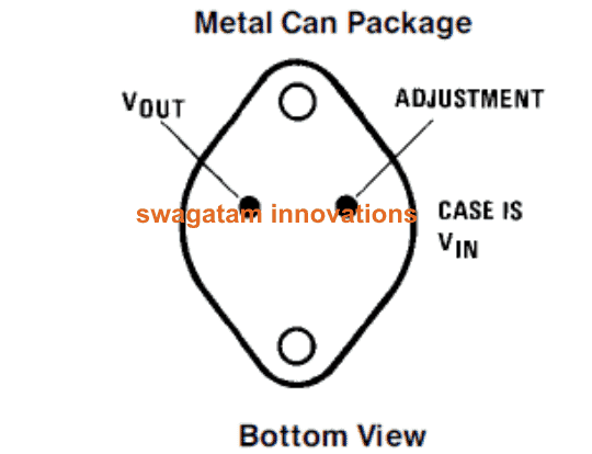
Pin out details of LM196
As given in the following diagram, from bottom with the larger area of the metal downward, the pin outs of the IC LM196 may be identified as follows:
- Right pin = Adjustment pin
- Left Pin = Output pin.
- Case or Body = Input
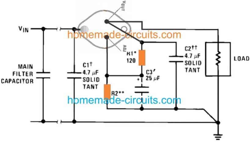
10 Amp Power Supply Circuit Using IC LM196 or LM396
The standard 10 amp voltage regulator circuit diagram using the IC LM196 can be witnessed in the following figure.
The calculations of the resistors are similar to that of IC LM338 or LM317. R2 may be adjusted to get the required regulated voltage at the output.
All the ground terminals involved in the circuit must be fixed with the main input ground which will be obviously the negative point of the bridge rectifier (not shown here). Similarly, the positive to the load must be directly acquired from the relevant lead of the IC.
The ground and the positive is taken from the main nodes due to the involvement of high currents with the circuit. As current increases, the conductor proportionately offers more resistance to the flow of the current which results in voltage drops at the output and hence unnecessary lengths of tracks should be avoided.


Questions & Answers
What voltage must the transformer have on the secondary to get 15V at the output? I assume that after the bridge rectifier the voltage must be at least 20V under load.
The input DC voltage must be around 3V higher than the intended output voltage, so the transformer voltage should be 13V to get 13 * 1.41 = 18.33V. But since 13V trafo is not a standard value you can try an 18V transformer or a 9V-0-9V.
To keep the IC cooler, you can eliminate the filter capacitor after the bridge, and instead connect the filter capacitor at the output side of the regulator.
Hi,
What is the suitable R2 value for 15v 10A output ?
Hi, it should be 13.2K
Sir, How can I add a variable current regulator in LM338 Circuit
Ajith, you can try implementing the following concept to your LM338 current limiter transistor
https://www.homemade-circuits.com/simple-current-sensor-circuit-modules/
Hi sir please I’m a very big fan of you since almost 15 years ago and I have build many of your circuit but please what I need from you or your help I have inverter but I need a circuit so that I can regulate the out put voltage to 220v ac because when I power the inverter it gives out put voltage amost 300v av so I need a circuit which can regulate to step it down to 220v ac
Thank you Daniel, I appreciate your response very much.
You can refer to the following article and try the second circuit for fulfilling your requirement:
https://www.homemade-circuits.com/load-independentoutput-corrected/
Hello,
I saw your recent post about the LM396/LM196 10A regulator. Do you know of any sources? They have been discontinued.
Thanks,
Mike
Hi, sorry I do not know about any online source. If you are having difficulty finding it you can use 2 LM338 in parallel, over a common heatsink.
I want to make a 5v 10a power supply but the only high amp regulator ic i have around ar lm338 and lm350. Can you please suggest any circuit for the desired power supply as i am just another hobbiest trying to power a 8x8x8 led matrix cube.
You can put the two ICs in parallel. Mount them on a common heatsink. Adjust the resistor values to 5V using this software:
https://www.homemade-circuits.com/lm317-lm338-lm396-calculator-software/
R1 = 120 ohms
R2 = 360 ohms
Hi sir, can you help me? I need a circuit with 12v and 10a max output, but the input is an solar panel with 30v and 15a max.
Thank you, salutes from Brazil.
Hi Dinilton, you can try the following concept and modify it accordingly as per your circuit specifications
https://www.homemade-circuits.com/5v-pwm-solar-battery-charger-circuit/
Hi swagatam I need a circuit that can cut off output of inverter 220v a.c on short circuit or over load protection pls
What is the percentage efficiency of LM196 when we convert 48 VOLTS to 12 VOLTS 10 amps
15V is the maximum that can be used with LM196
Hi Ajeet, you can refer to the following links,and select the one as per your requirement
https://www.homemade-circuits.com/?s=overload
am looking for a voltage regulator of 15volts 16 amps but I cant get it any suggestion.
you can put 4 LM338 IC in parallel and get the desired regulation from the configured circuit.
I want to make a power supply that runs 5 pc exhaust fans, so refer me power supply circuit…
and to receive 5 amp in the above mentioned circuit, how much amp transformer is needed?
Please specify the voltage and amp rating of the fans so that I can calculate the total power required from the power supply.
You can use LM338 in place of LM196 which would give you exactly 5amps, the IC would require a heatsink strictly.