A few of the interesting and useful hobby electronic circuit diagrams already published in this blog have been selected and compiled here for your quick reference and understanding.
What is a Hobby Circuit?
A hobby circuit is an electronic circuit project specially designed to suit new hobbyists. These circuits are mostly small and easy to built designs using minimum number of components.
New hobbyists can build these circuits quickly in their leisure time and have fun with the quick results obtained from these DIY circuits.
The following article presents a compilation of many assorted DIY hobby circuit projects, specially intended for all electronic enthusiasts and hobbyists.
RF Sensor without Battery
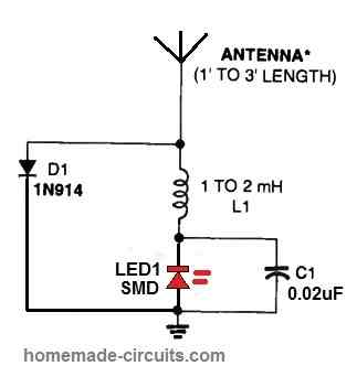
The circuit displayed above might be helpful for testing the RF output of RF transmitters.
The best feature of this detector circut is that it does not use any power source or battery. The detected RF signal is itself used for illuminating the LED1. But remember the LED must be high bright, RED SMD type LED.
If you have an amateur radio or CB transmitter which needs to be tested, switch ON the transmitter and the antenna of this circuit at touching distance of the RF transmitter antenna. You will find the LED1 turning on if the transmitter is emitting RF.
The circuit might be constructed inside a tiny metal or plastic box. A simple length of wire or a pull-up alternative antenna from an old TV or CB equipment could be used for the antenna.
NiCd Cell Zapper
Is your NiCd cell dead and refusing to accept charge? You may find the following simple method of reviving dead NiCd cells useful.
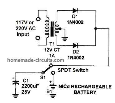
Here's an easy little circuit that may be occasionally used to zap a bad NiCd into accepting a charge and becoming usable again.
Many NiCds which have developed a problematic memory habit can benefit from this form of shock treatment. This approach might be worthwhile to explore if the particular NiCd refuses to accept a charge.
The NiCd zapper circuit consists only of a DC power source that charges up a huge electrolytic capacitor and discharges it via the chosen cell.
Use the zapper circuit with utmost caution and avoid over-pulsing the NiCd battery as the internal heating might result in an explosion of the NiCd! Make sure to cover the cell before zapping it!
Instead of a center tap circuit you can also use a two wire transformer with a bridge rectifier.
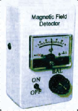
Magnetic Field Detector
The complete circuit schematic for the proposed Magnetic Field Detector presents itself in the following figure.
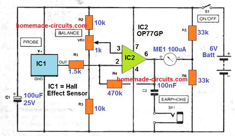
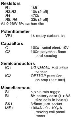
IC1 is the Hall effect sensor and 1C2 is a precision opamp IC2 rigged to deliver a bit of extra amplification. The op amp is configured in an inverting mode circuit, that includes resistors R1 and R4 positioned as negative feedback link.
The built-in voltage gain of IC2, or the "open loop" gain as it is actually called, is incredibly large at DC voltages, and lower frequencies. Actually, it can be more than 100,000 times for any standard opamp.
Applying negative feedback minimizes the design's voltage gain in general into a considerably more workable magnitude, and this "closed loop" gain is equivalent to the value of R4/R1. This breaks down to at slightly above 300 for the present design.
Increased voltage gain might naturally delivers improved sensitivity, however it might as well have its own complications due to noise and deviations.
Opamp 1C2 boosts the voltage difference between the input voltage and the R1 and the voltage at its non-inverting input (pin 3).
This subsequent voltage are adjustable by means of potentiometer VR 1, and practically it can be tweaked to generate a voltage that will have the exact normal output voltage through hall effect IC1 probe.
This generates 1 / 2 the supply voltage on the IC2 output.
The resistive divider created through resistors R5 and R6 in the same way generates an output of 1 / 2 the supply voltage. Meter ME1 is hooked up across the IC2 output and this particular voltage divider.
Therefore ME1 picks up the voltage difference across the two. In the standby mode, the two points happen to be with exactly the same voltage levels, displaying 0 voltage over the meter.
When the magnetic field is detected by the hall effet sensor, the IC1 output rises, causing a proportionate decrease across the IC2 output, which in turn generates a negative indication on the meter. When the IC1 output decreases, the IC2 output increases causing a positive defection on the meter.
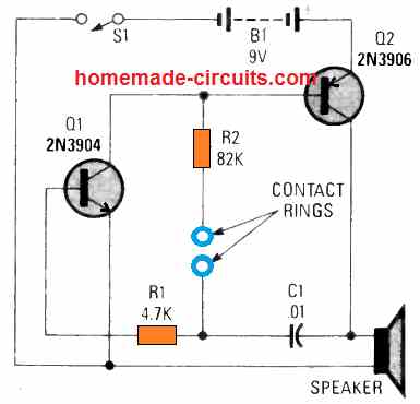
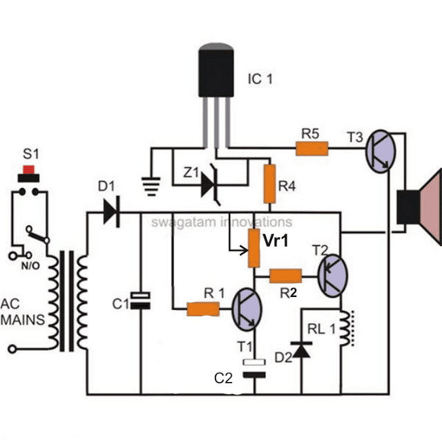
Lie Detector Circuit
The simple lie detector circuit will surprise you by its fairly accurate results. When you press your two fingers across the blue pads, and switch ON power, the speaker starts producing a low frequency sound.
The low frequency indicates that your fingers are not so moist and salty, because your body condition is normal and not in a stressful condition.
In case you happen to be in a lot of stress, or fear, your fingers starts releasing tiny amounts of fluid which is high in minerals and salts.
This situation is quickly detected by the lie detector circuit and the frequency tone from the speaker becomes shriller and sharper, indicating that either the person is in a great amount of stress, or may be the situation is because the person is trying to hide some facts, or simply lieing about the true answers to an asked question.
Electronic Fishing Lure
A very simple yet effective electronic fishing lure circuit can be seen in the following diagram, which is actually a simple piezo buzzer circuit, effectively applied as an electronic fishing lure or a fishing aid circuit
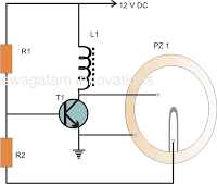
R1 is used for biasing the transistor T1, while R2 is used as the feedback interrupter which generates a negative feedback pulse from the piezo transducer each time the transistor conducts.
The negative feedback interrupts the biasing of T1 which causes the whole circuit to oscillate at a very high frequency, as determined by the inductor value and the piezo material specification.
The piezo here is a 27 mm standard piezo element. The must be properly covered with some non-conductive material, and immersed in water where the fishing lure is to be implemented.
The electrical vibrations from the piezo will be transmitted in the water to many meters down, causing the fishes to get attracted to the electrical pulses (imitating a buzzing fly), and accomplishing the fish luring action.
Making a Photo Cell using a Power transistor
This is an old trick I learned many years ago. Removing the round metal cap from a power transistor, in many cases, will reveal a photocell.
Even those that don't reveal a photocell have a base-emitter region that is sensitive to light when the cover is removed.
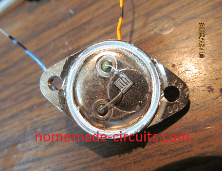
As shown in the photo, the metal cap has been removed and the photocell is located acroos the base-emitter pins.
This particular power transistor read 1250 ohms in darkness and 600 ohms under a light bulb. I removed the cap on a 2N456A and it does not show a photocell inside.
In darknesss, it reads 300 ohms. Under a light bulb, it reads 25 ohms. Removing the cover can be difficult.
The best way is to use a dremel tool with a metal cutting disc. A small hack saw could also be used. A last resort would be to take a small pair of sharp edge diagonal cutting pliers and pinch the metal at the round edges until the metal is penetrated.
Grab as much metal as possible and twist the pliers and metal upwards to expose the inside. Be careful not to damage the base-emmitter region.
The amount of resistance change,is going to vary with different types of power transistors.
Making small emergency capacitors
When you need a small size capacitor in an emergency, this is one method of making one. I made a 22 pf (.022nf) capacitor with pencil and paper as shown in the photo below.
You need a clean sheet of white paper, such as a typing sheet. You will also need a graphite pencil with a dull end and some scissors.
As the size shown resulted in 22pf of capacitance, you will need a smaller size for smaller pf's and larger for larger pf's.

Your actual capacitance values will depend upon the type of lead pencil you used and the pressure you applied to the paper sheet.
Start on one side and take the side of the pencil lead, making strokes to spread the graphite across the plate area and connection tab on one side.
Take care not to puncture the thin paper. Also leave a little room at the edges, so the opposite side plate will not short
The connector tabs should only have graphite applied on it's plate side. Turn the paper over and do the same thing on the opposite side.
The connector tab on the opposite side will be on the opposite end as compared with the front plate. Use a capacitance meter to test the capicatance.
If it is a smaller value than what you needed, just add more graphite to enlarge the plate area on both sides. If your tester doesn't identify any capacitance, check with an ohmmeter for a high resistance short.
You may have penetrated the paper and shorted the plates. Once you have the value required, take the scissors and allow some space from the graphite plates so you want be cutting into the graphite.
Connect pg (gator) type clips to the connector tabs and install it in your circuit. This is only a temporary fix as the environment, moisture, etc., could gradually change the value.
Also Highly Recommended: Projects for the Beginners
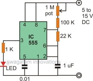
Simple Touch Sensitive Switch Circuit
We all know about this little versatile chip which finds its way in almost all useful electronic circuits, yes our very own IC 555. The following circuit is no exception, it's a sensitive touch switch circuit using the IC 555.
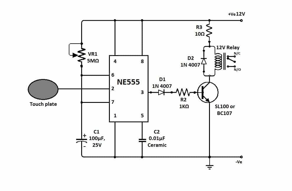
Here the IC is configured as an monostable multivibrator, in this mode the IC activates its output momentarily by producing a logic high in response to a trigger at its input pin#2.
The momentary activation time period of the output depends on the value of C1 and the setting of VR1.
When the touch switch is touched pin#2 is pulled to a lower logic potential which may be less than 1/3 of Vcc. This instantly reverts the output situation from low to high activating the connected relay driver stage.
This in turn switches ON the load attached with the relay contacts but only for the time until C1 gets fully discharged.
Simple Bistable Touch Switch
While there are plenty of prototypes for touch switches, creating a design that is easier than previous models is always a challenge.
Whereas most latching touch switches use a couple of wired NAND gates as a flip-flop bistable, this circuit just requires one non-inverting CMOS buffer, one capacitor and one resistor. As N1 's input is held low by bridging a finger with the lower set of touch points, N1 's output goes low.
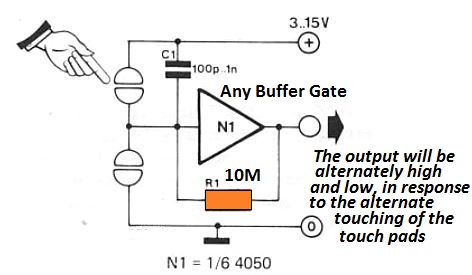
The input of N1 is kept low by the output through R1 when the contacts are released, hence the output remains low permanently.
The input of N1 is rendered high when the upper set of contacts are bridged, so that the output goes high. Once the contacts are released, the input is kept high through R1, and therefore output stays high.
Simple 50 Hz Hum Filter
There are also situations where it is beneficial to be able to remove of unnecessary interference with the mains (50 Hz).
The easiest way of doing that is to use a special filter that only eliminates the 50 Hz signal components while passing unchanged other signal frequencies, i.e. a highly selective filter. A typical circuit is illustrated in figure 1 for such an filter.
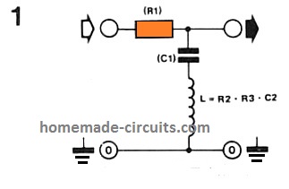
While a filter with a notch frequency of 50 Hz and a Q of 10 will require nearly 150 Henries inductance, the most easiest answer is To electronically synthesize the intended inductance (see Figure 2).
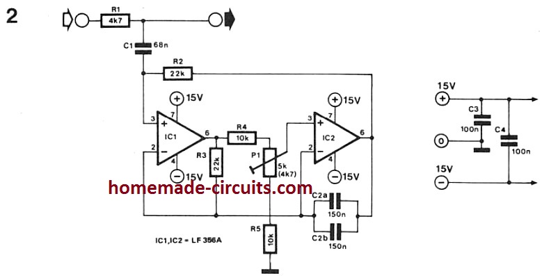
Together with R2 … R5, C2 and P1, the two opamps give a rather ideal simulation of a traditional wound inducer located within two pin3 of IC1 and earth. The resulting inductance value is equal to the sum of the R2, R3 and C2 values ( i.e., L = R2 x R3 x C2).
With P1 this value could be slightly changed for tuning purposes. The attenuation of 50 Hz signals is 45 to 50 dB when the circuit is calibrated correctly.
The circuit can be used in harmonic distortion as a hum-rejection filter for TV sound signals, meters or as hum filter.
Fluorescent Lamp Dimmer Circuit
It is not possible to control the light level of fluorescent lamps through traditional light dimmers, except if specific modifications are executed.
In the circuit detailed here the heater filaments of the fluorescent lamp are pre-heated using a heater transformer with a pair of individual windings.
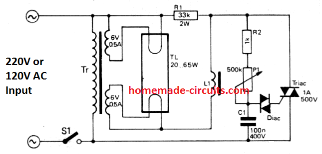
The starter is ignored, but the choke (L1) can be allowed to be in the circuit. The (standard) triac control stage is attached by using the choke with a 33 k/2 W 'bleeder' resistor across the tube and choke to provide current to the dimmer when the tube is shut down. On the other hand, 3 100 K resistors 1/4 W could be joined in parallel.
Any kind of suppression systems existing in the triac dimmer must be taken off; the large self-inductance of L1 may limit the interference due to the dimmer to a lowest.
When the range of fluorescent light intensity control is found inadequate, you possibly can test out the value of capacitor C1.
Regular safety measures must, obviously, be weaned: the circuit should be installed on an insulation box, P1 must have a plastic spindle, and Cl needs to be a 400 V rated.
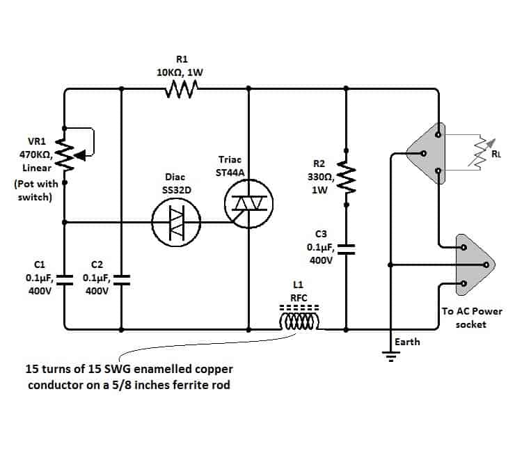
Simple Triac Dimmer Circuit
The circuit of a simple triac light dimmer shown below can be used for dimming incandescent lamps directly from AC mains.
The circuit is very easy to construct and uses very few components. The pot is used for controlling the load power or the intensity of the light. The dimmer circuit can be also used for controlling ceiling fan speeds.
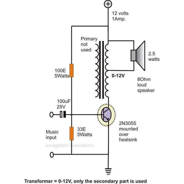
Simple Audio Power Amplifier Circuit
The circuit illustrated here is probably the simplest form of an audio power amplifier.
Though the circuit is very crude by its specs yetis able to amplify an audio input up to a powerful 4 watts in a 8 Ohm speaker.
The transistor used in this amplifier is a 2N3055 is used as a switch for inducing voltages in response to the input signals into one half winding of the transformer.
The back emf generated across the winding of the transformer is effectively dumped over the speaker generating the required amplifications. The transistor needs to be mounted on a suitable heatsink.
Simple FET Audio Mixer
Low-cost junction-FETs as explained here could typically be used favorably to low frequency circuits. In a small-scale audio-mixers the application of JFET5 contributes to an excellent saving in parts due to relative ease of the biasing techniques.
The input impedance of each channel is established solely by the magnitude of the potentiometer used.
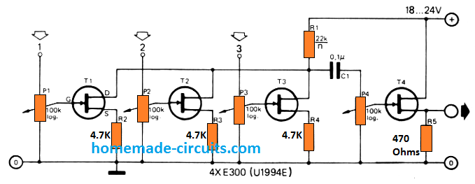
The quantity of input channels could be significantly extended, in case it is demanded, so long as the common drain load resistor (RI) is appositely selected.
Its value may be the regular value nearest to 22k / n, where n is actually the quantity of input channels
Simple Water Level Alarm Circuit
Just a couple of transistors are enough for implementing a simple water level alarm circuit and used for getting a warning signal when the water level inside a tank nears the overflowing level.
The two transistors are configured as a high gain, high sensitive switch, which also is capable of generating a tone when the shown terminals get bridged through the terminals coming in contact with the water inside the tank.
The water offers just about the right resistance value across the specified points of the circuit for initiating high pitched tone or the desired warning alarm.
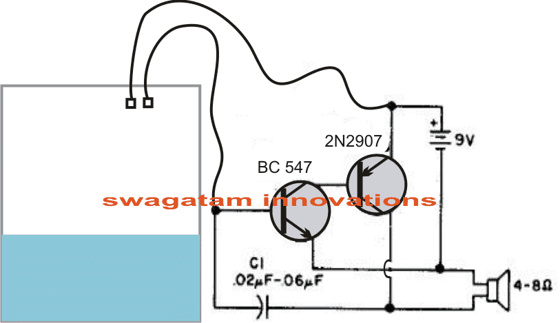
How it Works
When water level touches the probes, the base of the BC547 gets the required biasing voltage through the probes and switches ON.
This causes the 2N2907 also to switch ON since its base is connected to the collector of the BC547.
When the 2N2907 switches ON, it operates the loudspeaker.
When the loudspeaker coil moves it generates a back EMF which sends a negative voltage to the base of the BC547 via C1. This back emf turns OFF the BC547 instantaneously.
When the BC547 turns OFF the 2N2907 also turns OFF. The circuit now reaches its original position.
In this position the current through the water yet again switches ON BC547 and the process repeats to generate the required buzzing sound from the speaker.
Simple Temperature Detector Circuit
A very simple temperature indicator circuit can be built using the circuit shown in the diagram.
A generally purpose small signal transistor is used here as the sensor and another active device in the form of a1N4148 diode is used for providing a reference level to the sensing operation.
The heat source which is to be measured is place in contact with the transistor while the diode is held at a relatively constant ambient temperature level.
As per the setting of the preset P1, if the threshold is crossed by the introduced heat source, the transistor begins to conduct substantially, illuminating the LED and indicating the generation the heat beyond a particular set limit.
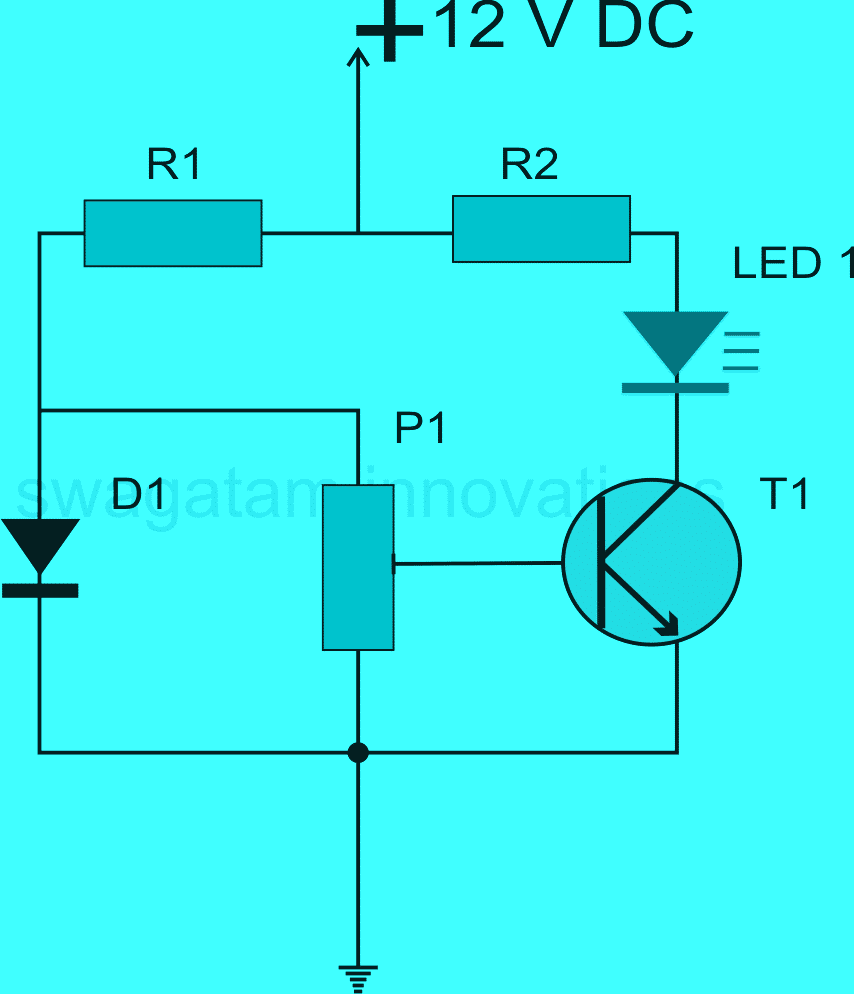
Parts List for the above simple transistor hobby circuit
- R1 = 1K,
- R2 = 2K2,
- D1 = 1N4148,
- P1 = 300 Ohms,
- T1 = BC547
- LED = RED 5mm
100 Watt Transistor Based Inverter Circuit

Inverters are devices which have important applications where normal electric supply is not available or difficult to obtain through conventional routes.
The simple 100 watt inverter circuit shown here can be built and used for powering many electrical appliances like, lights, soldering iron, heater, fan etc. The whole 100 watt inverter circuit mainly involves transistors and therefore becomes easier to construct and implement.
Parts List
- R1, R4 = 330 Ohms,
- R2, R3 = 39K,
- R5, R6 = 100 Ohms, 1watt,
- C1, C2 = 0.47uF,
- D1, D2 = 1N5402
- T1, T2 = BC547,
- T3, T4 = TIP127,
- T5, T6 = 2N3055,
- Transformer = 9-0-9V, 10Amp, 220V or 120V
100 Watt Transistor Power Amplifier Circuit
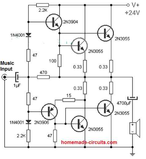
This circuit of a transistor power amplifier is outstanding with its performance and is able to provide a thumping 100 watts of pure music output.
As can be seen in the diagram it utilizes mainly transistors for making the amplifier and its implementations and a handful of other inexpensive passive components like resistors and capacitors. The required input is not more than 1 V, which gets amplified 200,000 times at the output.
Simple 10 Watt Amplifier Circuit
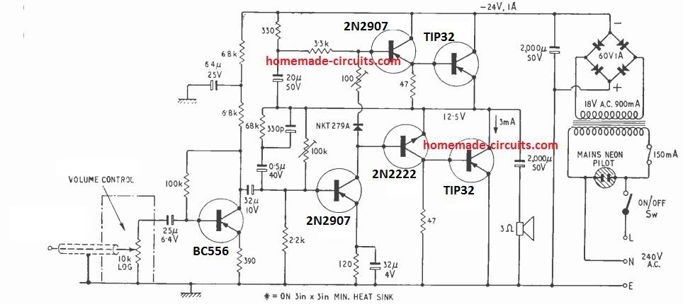
This a simple transistorized 10 W power amplifier, mains driven circuit, which will deliver 10 watt into a 4 ohm loudspeaker. The input sensitivity of the amplifier is 100 mV input sensitivity, input resistance is 10 k.
Before using make sure to optimize the 100 ohm preset for setting up the quiescent current correctly. Meaning to ensure that the amplified draws minimum possible current in the absence of an input signal.
To do this connect a small 10 mA bulb in series with the positive line. Short the input line with the ground, also short the speaker terminals.
Now switch ON power and adjust the 100 ohm preset until the bulb illumination is almost zero.
The 100 k preset sets the gain of the amplifier.
Simple Automatic Emergency Lamp Circuit

This simple emergency lamp circuit uses very components and yet is able to provide some useful service.
The shown device is able to switch ON automatically when mains power fails, illuminating all the connected LEDs.
As soon as power is restored, the LEDs shut off automatically and the connected starts charging through the built in power supply.
The emergency light circuit employs a transformerless power supply for initiating the explained automatic actions and also for trickle charging the connected battery.
Parts List for the above CIRCUIT DIAGRAM
- R1 = 220K,
- R2 = 10K,
- D1, D2, D3 = 1N4007,
- Z1 = 15V 1watt, zener diode,
- C2 = 100uF/25V
- LEDs = white, high bright type.
Automatic Day Night Light Switch Circuit
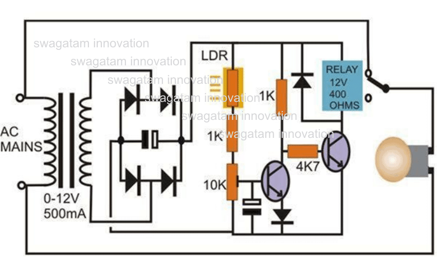
This simple transistor circuit can be used for monitoring the dawn and dusk conditions and for switching lights in response to the varying conditions.
Thus the day night light switch circuit can be used for switching ON the connected lights when night sets in and switch it OFF during day break. The threshold tripping point may be set by adjusting the 10K preset.
The capacitors are 100uF/25V, the transistors are ordinary BC547, and the diodes are 1N4007.
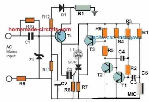
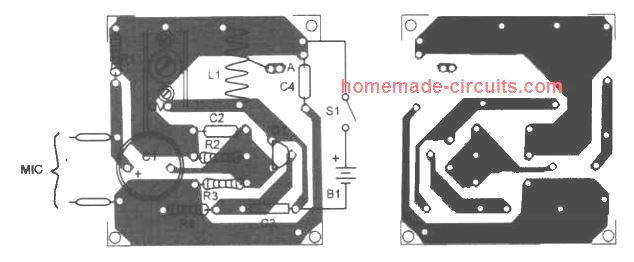
Electronic Candle Circuit
- R1 = 5k6
- R2 = 47k
- R3 = 3M3
- R4 = 33K
- R5, R7 = 330 OHMS
- R6, R8 = 2K2
- R9 = 22 ohms 1 watt
- R10 = 330k
- R12 = 1k
- C1 = 0.33uF/400V
- C2 = 4.7uF/25V
- C3 = 0.1uF/25V
- C4 = 1uF/25V
- T1, T2 = BC547
- T3, T4 = BC557
- D1 = 1N4007
- LED = Amber high bright 3 V, 20 mA
- B1 = Ni-Cd Cell
This is a simple hobby project and exhibits all the properties of a conventional wax type candle. Here the LED is used in place of the candle flame, which illuminates as soon as the mains power fails and shuts off automatically when the power is restored.
So it also performs the function of an emergency lamp. The connected battery is used for powering the candle”light and it is charged continuously when the unit is not being used and powered through the mains supply.
An interesting “puff off” feature is also included so tatthe “candle” light may be switched OFF whenever desired through a puff of airinto the attached mic which acts as the air vibration sensor.
Simple Emergency Flashlight Circuit
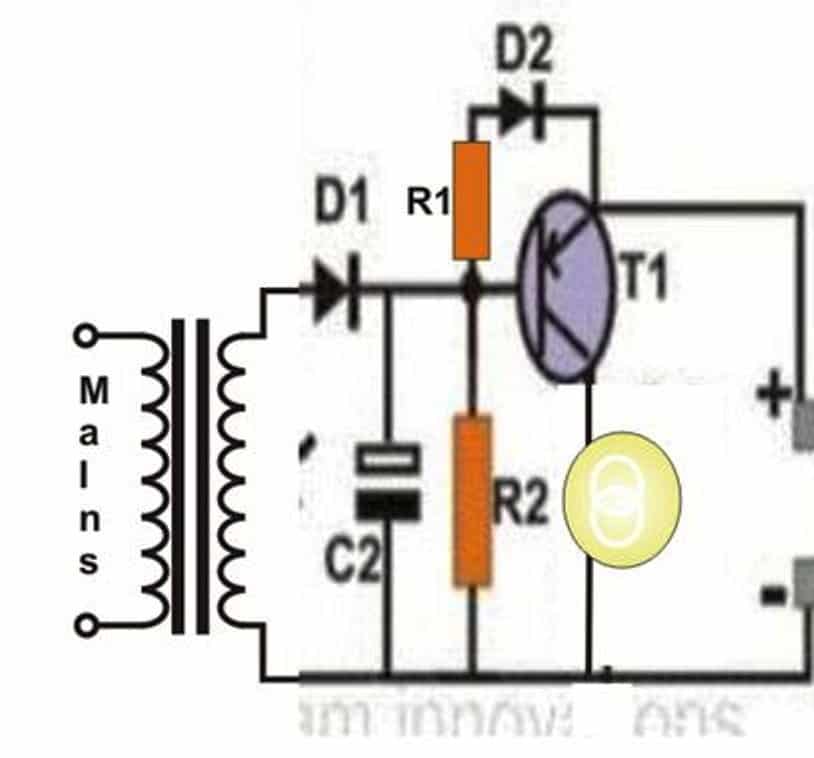
This circuit may be used as an automatic emergency lamp when there’s no power or when mains power fails during night times.
As shown in the diagram, the circuit utilizes a cheap incandescent flashlight bulb for the required illumination.
As long as the input supply from the mains transformer is present the transistor remains switched OFF and so does the lamp.
However the moment the mains power fails, the transistor conducts and switches ON the battery power to the bulb, instantly illuminating it brightly.
The battery is trickle charged for so long as the mainspower remains connected to the circuit.
Parts List
- R1 = 22 Ohms,
- R2 = 1K,
- D1 = 1N4007,
- T1 = 8550,
- Lamp = 3V flashlight bulb.
- Transformer = 0-3V, 500 mA,
- Battery = 3V, penlight 1.5 V cells (2nos. in series)
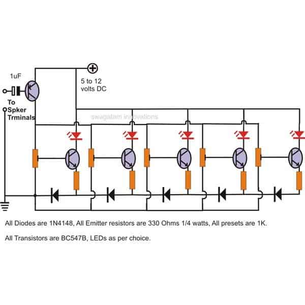
Music operated Dancing Light Circuit
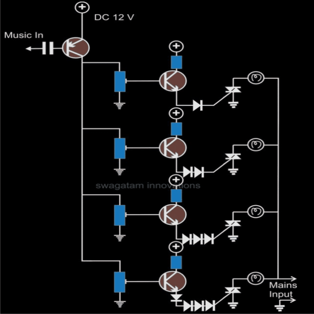
This circuit may be used for transforming music into dancing light patterns.
The operation of the music lamp circuit is very simple, the music input is fed to the bases of the shown transistor array, each of them are configured to conduct at a specific voltage level in the incrementing order from the top to the bottom transistor.
Thus the uppermost transistor conducts with the input music is at the minimum volume level and the subsequent transistor starts to conduct in sequence as per the volume or the pitch of the music.
Each transistor is rigged with individual lamps which light up in response to the music levels in a “chasing” dancing light pattern.
Parts List
- All the base presets are = 10K,
- All the collector resistors are 470 Ohms,
- All the diodes are = 1N4148,
- All NPN transistors are = BC547,
- The single PNP transistor is = BC557,
- All the triacs are = BT136,
- The input capacitor = 0.22uF/25V non polar.
Simple Clap Switch LED Lamp Circuit
- R1 = 5k6
- R2 = 47k
- R3 = 3M3
- R4 = 33K
- R5, R7 = 330 OHMS
- R6 = 2K2
- C1 = 0.33uF/400V
- C2 = 4.7uF/25V
- T1, T2 = BC547
- T3 = BC557
- D1 = 1N4007
- LED = RED LEDs 3 V, 20 mA
The interesting clap switch circuit shown here can be used in stairways and passages for illuminating the premise momentarily through clap sound.
The circuit is basically a sound sensor circuit with an enclosed amplifier stage.
The clap sound or any similar sound is detected by the mic and converted into minute electrical pulses. These electrical pulses are suitably amplified by the subsequent transistor stage.
The Darlington stage shown at the output is the timer stage which switches in response to the above sound interaction and illuminate the connected LEDs for some period of time defined by the 220K resistor and the two39 K resistors.
After the time lapses the LEDs are switched off automatically and the clap switch circuit returns to its original state until the next clap sound is detected.
The parts list is given in the circuit diagram itself.
A Simple ELCB Circuit

The circuit shown here can be used for detecting earth leakage conditions and for implementing the required shutting off the mains power supply.
Unlike usual configurations, here the ground to the ELCB circuit and the relay is acquired from the earthing line itself.
Also since the input coil is also referenced to the common earthing ground, the entire functioning becomes compatible and accurate.
On sensing a possible current leakage at the input, the transistors come into action and switch the relays appropriately. The two relay have their individual specific roles to play.
One relay detects and switches OFF when there’s current leakage through an appliances body, while the other relay is wired up to sense the presence of a the earthing line and switches OFF the mains as soon a wrong or weak earthing line is detected.
Parts List
- R1 = 33K,
- R2 = 4K7,
- R3 = 10K,
- R4 = 220 Ohms,
- R5 = 1K,
- R6 = 1M,
- C1 = 0.22uF,
- C2, C3, C4 = 100uF/25V
- C5 = 105/400V
- All diodes = 1N4007,
- Relay = 12V, 400 Ohms
- T1, T2 = BC547,
- T3 = BC557,
- L1 = output transformer as used in radio push pull amplifierstage
Simple LED Flasher
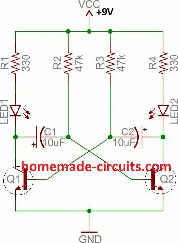
A very simple LED flasher circuit is illustrated in the diagram. The transistors and the corresponding parts are connected in the standard astable multivibrator mode, which forces the circuit to oscillate the moment power is applied.
The LEDs connected at the collector of the transistors start flashing alternately in wig wag manner.
The next diagram below shows how the LEDs can be connected in series and parallel, so that many numbers of LEDs can be accommodated in the configuration.
For getting different interesting flashing patterns with the LEDs, you can add separate pots in series with R2 and R3.
Adjusting the pots individually will produce different flashing patterns on the LEDs which can equal across the two channels, or with different flashing rates depending on how the two pots are adjusted.
The pots can be rated at 100k. If pots are used in series with R2 and R3, then the values of R2 and R3 must be changed to 10K each.

Parts List
- R1, R2 = 1K,
- P1,P2 = 100K pots,
- C1, C2 = 33uF/25V,
- T1, T2 = BC547,
- Resistors connected with each LED series = 470 Ohms
- LEDs are 5mm type, color as per choice.
Simple Wireless Microphone Circuit
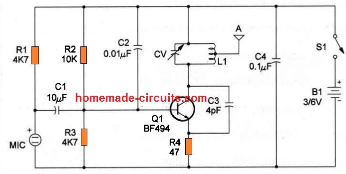
Anything spoken into the mic of the presented circuit cab be clearly picked up and reproduced by any standard FM radio, within a range of 30meters of distance.
The circuit is very simple and just requires ther shown components to be assembled and connected with each other as depicted in the diagram.
The coil L1 for this FM transmitter circuit consists of 5 turns of 1mm super enameled copper wire, having a diameter of around 0.6 cm.
Parts List
- R1 = 4K7,
- R2 = 82K,
- R3 = 1K,
- C1 = 10pF,
- C2, C3 = 27pF,
- C4 = 0.001uF,
- C5 = 0.22uF,
- T1 = BC547
Single IC Transmitter Circuit
In the above section I have explained how to build a simple single transistor transmitter circuit, however a low range test transmitter could be also built using a single IC.
Yes, no need of any inductor, no complex tank circuit, no tuning nothing.
Just hook up a few resistors, and an antenna with the NOT gates from the IC 4049, and your tiny little audio transmitter is ready, which can send a sharp frequency signal to nearby AM radio.
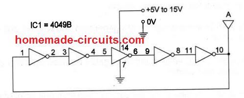
However, there's also a possibility to convert this single IC transmitter into a tunable AM transmitter by adding a 10k pot in series with the supply, or by adding a variable gang condenser or a trimmer in series with the antenna, as shown in the following diagrams.
40 LED Emergency Light Circuit
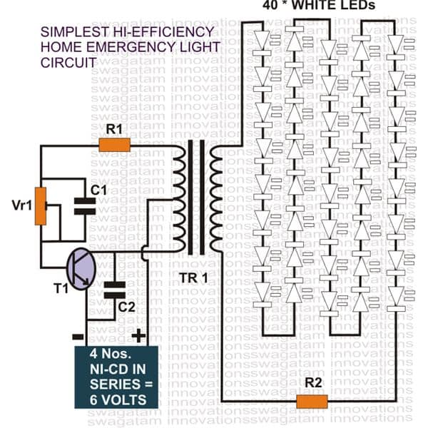
The shown design of a 40 LED emergency light is driven using an ordinary transistor/transformer inverter circuit.
The transistor and the respective winding of th transformer are configured as a high frequency oscillator stage.
The oscillations induce a high voltage across the winding of the transformer. The stepped-up voltage at the output is directly used to drive the LED which are all connected in series for getting the desired balance and the illumination.
Parts List
- R1 = 470 Ohms,
- VR1 = 47K,
- C1, C2 = 1uF/25V
- TR1 = 0-6V, 500mA,
- Battery = 6V, 2AH,
- LEDs = high bright white, 40 nos.
Simple Transistor Latch Circuit
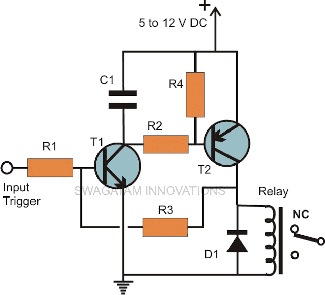
If you are looking for a circuit which can be used to latch the output in response to an input signal, then this circuit can be used for the intended purpose very effectively and also very cheaply.
A momentary input trigger is applied to the base of T1,which switches it for a fraction of a second depending upon the length of the applied signal.
The conduction of T1 immediately switches T2 and the connected relay.
However at the very instant a feedback voltage also appears at the base of T1 via R3 from the collector of T2.
This feed back voltage instantly latches the circuit and keeps the relay activated even after the trigger from the input is removed.
Parts List
- R1, R3 = 100k,
- R2, R4 = 10K,
- C1 = 1uF/25V
- D1 = 1N4148,
- T1 = BC547,
- T2 = BC557
- Relay = 12V, SPDT
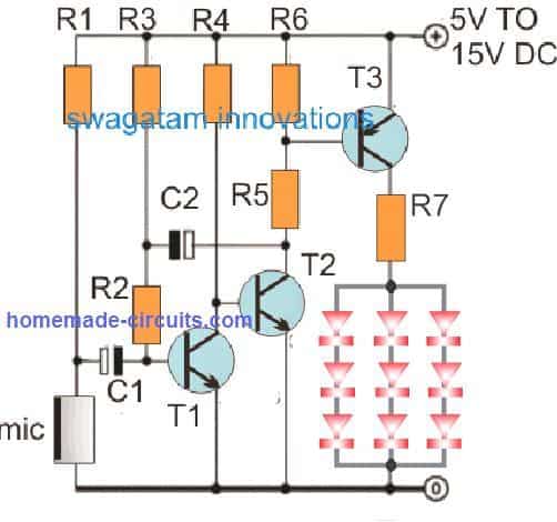
Simple LED Music Light Circuit
In one of the previous sections we studied a simple music light show circuit using mains operated incandescent lamps, the present design incorporate LEDs for similar intended light show generation.
As can be seen in the figure, the transistors are all wired up in sequencing array. The music signal varying with pitch and amplitude is applied at the base of the buffer amplifier PNP transistor.
The amplified music is then fed across the whole array where the respective transistor receive the inputs with incrementing pitch or the volume levels and go on switching in the corresponding manner from start to finish, producing an interesting LED light sequencing pattern.
This light exactly varies its length according to the pitch or the volume of the fed music signal.
Parts list is provided in the diagram.
A Simple 2-Pin Automobile Indicator Lamp Flasher Circuit with Buzzer
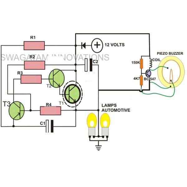
If you want to make a flasher unit for you motorbike then this circuit is just for you. This simple turn signal flasher circuit can be easily built and installed in any two wheelers for the desired actions.
The automobile flasher circuit employs just two 2-pins instead of 3 as found in other flasher circuits. Once installed, the circuit will faithfully flash the side indicator lights whenever the intended function is switched ON.
The circuit also incorporates an optional buzzer circuit which can be also included for getting a beeping sound in response to the flashing of the lamps.
Parts List
- R1, R2, R3 = 10K
- R4= 33K
- T1 = D1351,
- T2 = BC547,
- T3 = BC557,
- C1, C2 = 33uF.25V
- L1 = Buzzer Coil
Simple Relay Motorbike Flasher Circuit
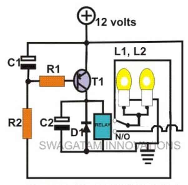
In the above section I have explained a simple three transistor based flasher circuit; here we study another similar design, however here we incorporate a relay for the switching actions of the lamps.
The circuit looks pretty straightforward and employs hardly anything substantial and yet performs the expected functions wonderfully well.
Just build it and wire it in your mo-bike for witnessing the intended functions...
Parts List
- R1 = 1K,
- R2 = 4K7,
- T1 = BC557,
- C1 = 100uF/25V,
- C2 = 1000uF/25V
- Relay = 12V, 400 Ohms
- D1 = 1N4007
Simple Triac Flasher Circuit
This circuit is designed to flash a standard incandescent lamp flash at any rate between 2 and about 10 Hz determined by the 100 K pot.
The 1N4004 diode rectifies the mains input AC, which is fed to a variable RC network stage. The moment the electrolytic capacitor gets fully charged, it reaches the breakdown voltage of the diac ER 900 (or DB-3).
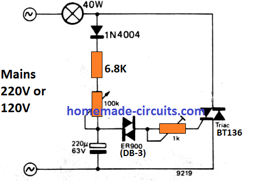
Next, the capacitor begins discharging through the diac, which fires the triac causing the connected lamp to illuminate brightly and shut off.
After some delay as preset by the 100 k pot, the capacitor begins recharging again to the breakdown limit of the diac, causing the lamp to pulse and shut down.
The process continues allowing the lamp to flash at the specified rate. The 1 k decides at what current threshold the triac is supposed to fire.
Simple Door Bell Timer, with Adjustable Timing Facility
Yes this simple transistor circuit can be used as a home door bell and it’s ON time can be set as preferred by the user, meaning if you wanted that the sound of the bell to remain switched ON for a particular period of time, you could easily do it just by adjusting the given pot.
The actual tune is derived from the IC UM66 and the associated components, while all the included transistors along with the relay are configured for producing the time delay for keeping the music switched ON.
Parts List
- R1, R2, R4, R5 = 1K
- VR1 = 100K,
- D1, D2 = 1N4007,
- C1, C2 = 100uF/25
- T1, T3 = BC547,
- T2 = BC557
- Z1 = 3V/400mW
- Transformer = 0-12V/500mA,
- S1 = Bell Push
- IC = UM66
Timer Circuit with Independent On and OFF Delay Adjust Facility
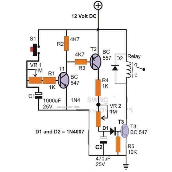
The circuit can be used for generating delays at a desired rate. The On time of the relay can be controlled by adjusting the Pot VR1 while the pot VR2 may be used to decide after how long the relay responds once the input trigger is fed by the switch S1.
The parts list is enclosed inside the diagram.
Simple High and Low Mains Voltage Cut Off Circuit
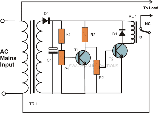
Are you having problems with your input Mains supply? That’s common problem associated with our input mains AC line, where a high and a low voltage conditions are quite frequently encountered by us.
The simple high low voltage controller circuit shown here can be built and installed in you house electrical board for getting a 24/7 safety from the possible dangerous AC voltage conditions.
The circuit keeps the relay and the wired appliances as long as the mains input stays within a safe tolerable level and switches the load OFF the moment a dangerous or unfavorable voltage condition is sensed by the circuit.
Parts List
- R1, R2 = 1K,
- P1, P2 = 10K Preset,
- T1, T2 = BC547B,
- C1 = 100uF/25V,
- D1 = 1N4007
- RL1 = 12V, SPDT,
- TR1 = 0-12V, 500mA
0 – 40 V, 0 – 4 Amp Continuously Variable Power Supply Circuit
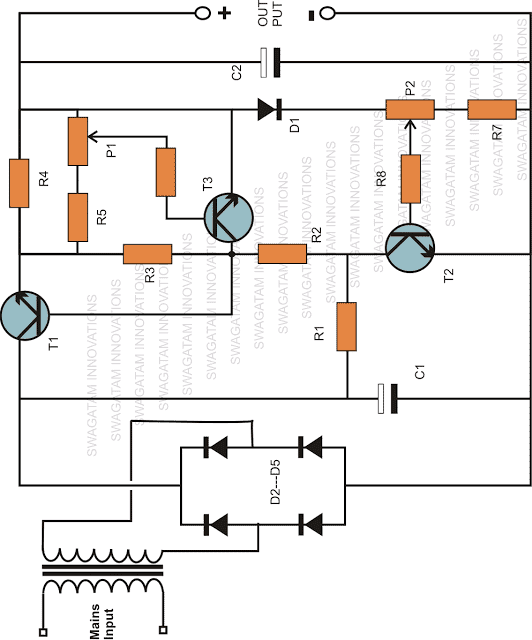
This unique work bench circuit utilizes only a few inexpensive transistors and yet delivers some truly useful features.
The feature includes continuously variable voltage from zero to the maximum transformer voltage and current variable from zero to the maximum applied input level.
The output of this power supply is also over load protected. The pot P1 is used for setting the maximum current while the pot P2 is used for varying the output voltage level up to the desired levels.
Parts List
- R1 = 1K2,
- R2 = 100 Ohms,
- R3 = 470 Ohms,
- R4 = Evaluate using Ohms law.
- R5 = 1K8,
- R6 = 4k7,
- R7 = 68 Ohms,
- R8 = 1k8,
- T1 = 2N3055,
- T2, T3 = BC 547B,
- D1 = 1N4007,
- D2, D3, D4, D5 = 1N5408,
- C1, C2 = 2200uF/50V,
- Tr1 = 0 – 35 Volts, 3 Amp
Simple Crystal Tester Circuit
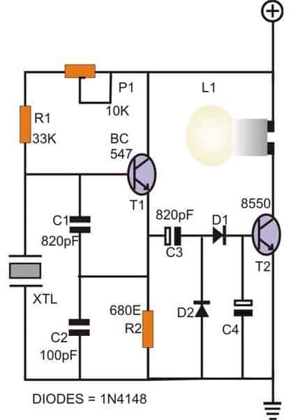
When it comes to frequency generating circuits or rather precise oscillator circuits, crystals become a crucial part, especially because they play an important role for generating and maintaining accurate frequency rates of the particular circuit.
However these devices are prone to many defects and are normally difficult to check through conventional DMM units.
The shown circuit can be used for checking all types of crystals instantly. The circuit itself is a small transistor oscillator circuit which starts oscillating when a good crystal is introduced across the indicated points in the circuit.
If the crystal is a good one, the bulb lights up showing the relevant results and if there’s any defect in the attached crystal, the bulb remains switched OFF.
Simple Current Limiter Circuit Using two transistors
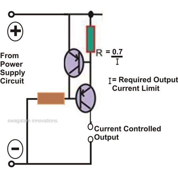
In many critical applications, circuits are required to maintain a strict controlled magnitude of current through them of at their outputs.
The proposed circuit is exactly meant for carrying out the discussed function.
The lower transistor is the main output transistor which operates the output vulnerable load and by itself is unable to control the current through it.
The introduction of the upper transistor makes it sure that the base of the lower transistor is allowed to conduct as long as the current output is within the specified limits.
In case the current tends to cross the limits, the upper transistor conducts and switches OFF the lower transistor inhibiting any further passage of the exceeded current limit.
The threshold current may be fixed by R which is calculated with the shown formula.
Old Person Monitor Circuit
An aged family member who stays with us sometimes falls down by accident, and often lies on the ground for quite a while in a troubled condition without being in a position to call for help. Keeping this critical issue in mind, , a straightforward self-sufficient alarm was developed and the completed design is demonstrated below.
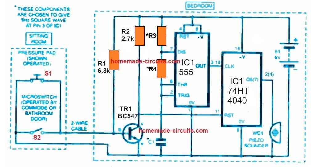
Unless of course a "reset" action is employed until a specific period of time has lapsed the alarm will automatically start buzzing.
The working theory of this older person alarm could be tailored as necessary and could motivate some other concepts.
As long as the old individual is resting in bed a pressure button (S1) or a press switch beneath the bed mattress is maintained in closed circuit status.
This allows the 4040 IC2 in its reset condition through transistor TR1 therefore, the piezo sounder WDI remains turned OFF. Clock pulses of roughly 1 Hz frequency are generated constantly through the 555 timer IC1 (pin 3) towards the counter input of IC2 at pin 10.
However, this action has no effect on the circuit until the individual gets up from the bed (for this action you can also consider a commode or simply, the bathroom door) after which the counter circuit becomes activated and it starts counting.
In the event that the time taken by the elderly person from the bed to the commode or bathroom exceeds a predertermined time (the bathroom can be used for activating microswitch S2 fixed on the bathroom door which resets the timer back to zero) the counter output Q6 (or Q7 perhaps) goes high.
This in turn causes the alarm WD1 to sounds which may be situated in a adjoining area to ensure that anybody can check out and make sure the individual is completely OK.
A hold off between one and two minutes had been chosen to let the aged individual have enough time and also due to the fact in real life the microswitch S2 was not always triggered.
For the present circuit the switch unwraps as soon as the person departs the commode, and thus IC2 begins counting.
When the time person's returning to bed is much too long (which resets the counter) is yet again very long for the alarm to trigger ON, it means that individual is upright, or is going back to bed or might have fallen down.
Considering that an older individual is not likely to keep standing up over (say) 2 minutes and is particularly impossible to take more than 2 minutes to come back to bed, it is most likely that this person has slipped. The prototype can be powered through a safe 6V battery, that may be standard rechargeable.
Head or Tails Decision Maker
The electronic heads or tails can be used to make important decisions in a perfectly electronic way. When the button is pressed the 'silicon chip technology' will very efficiently and in a fool proof way provide the 'yes' or 'no' or simply heads or tails answer within a some millisecond.
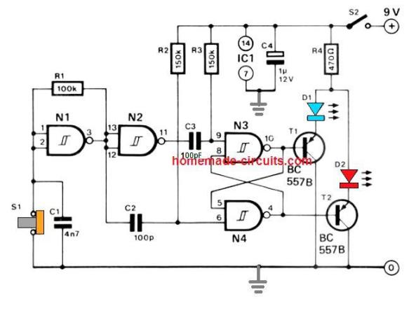
Gate N1 combined with R1 and C1 works like a square wave generator stage which, by means of N2 controls the flip-flop which involves N3 and N4.
Couple of outputs of the flip-flop turn the LEDs D1 and D2 and ON/OFF alternately through transistors T1 and T2. The push button, when pressed, causes the LEDs to blink at very very fast.
As soon as the user releases the push button only one particular LED out of the two remains lit while the other one is completely OFF. The LEDs can be labelled 'heads' or "tails" and as a result provide the decision which is completely random in nature.
A 3rd LED for 'not sure' had been thought of, however it was terminated because today's professional are eligible to make several decisions for themselves…
On a serious note, the circuit is outstandingly sensible and the output for 'heads and tails' is unquestionably correct and 100 % random!
Well, I am sure there can be countless number of hobby electronic circuits that can be included here, however for the moment I could gather only these many, if you think I might have missed a few you may simply feel free to update the same through your valuable comments....
Neon Sign Driver Circuit
If you are having a 220 V neon sign lamp, and wondering how to illuminate it with a battery, then this simple 555 circuit will solve your problem.
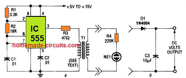
This IC 555 inverter will transformer a 6 V or 12 V battery to 220V low current output for driving or illuminating any neon sign amp or tube.
The transformer T1, can be built on any standard E core ferrite assembly, with 10 turns on the primary side, and the 200 turns on the secondary side.
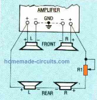
Simple Surround Sound
THE EASIEST SETUP OF THE HAFLER CIRCUIT. The left and right backside speakers receive the same L -R signal.
In case their efficiency can be so small that they stop being too much loud on the majority of audio content, R1 may be removed.
Just one rear end speaker is enough to deliver when its impedance is 8 ohms or more. (This eliminates straining the amplifier.)
It must be mounted at the middle rear, ideally facing all the way up or toward the back wall to promote reflecting rebound.
Enhanced Surround Sound Music
THE NEXT CIRCUIT BELOW DELIVERS ENHANCED SURROUND-SOUND EFFECT than the above, and may be more effective with rock than jazz music.
Resistors R1 and R2 must be tweaked concurrently for getting the correct comparative front-to-rear ranges. The settings of R1 and R2 will correspond, to little extent, on the user's seating position.
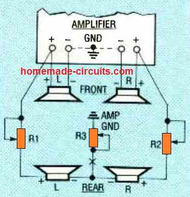
Resistor R3 is fine-tuned by listening to the audio, so as to deliver a little bit of blending of the front L and R signals into the backside speakers .
In case preferred, an on/off switch could be fitted at X to get rid of the mixing of the music across the rear channels.
If your amplifier comes with an A-B switch to work with an additional pair of speakers, the rear-speaker circuit, (a) or (b), could be hooked up straight to the positive B terminals.
This can make it possible for easy on-off switching of the rear channels.
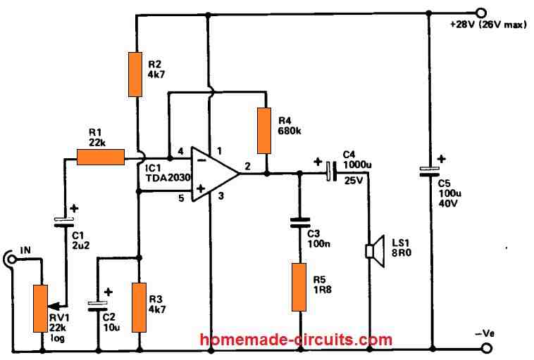
Single IC Power Amplifier
Employing a 28 volt supply, this handy amplifier could give an output power of up to around 8 watts rms into an 8 ohm loudspeaker with low distortion (less than 0.1 percent THD).
When utilized with a 4 ohm loudspeaker, the output power rises to around 12 watts rms or so, with distortion approximately quadrupled (although still at the lower end).
The circuit will work with smaller output voltages, such as around 9 volts, but the highest output power will be reduced.
A TDA2030 integrated circuit is used in the circuit, which is a contemporary device that is faster and easier to operate than most older devices.
DC Over Voltage Protector
Parallel with the 12 V supply lines, a silicon-controlled rectifier is placed and hooked up to a normally-closed 12 V relay, K1.
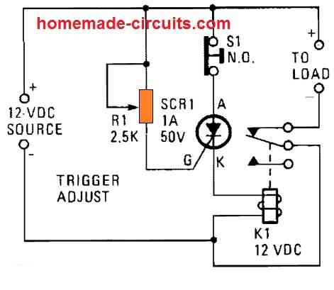
The applied voltage is sampled using the SCR's gate circuit. SCR1 stays off and K1's contacts remain closed so long as the applied voltage maintains below a certain amount, delivering current to the load.
Once the source voltage increases over 12 V, enough current is delivered to SCR1's gate forcing it to conduct , and switch ON the relay to shut down the load.
This protects the load from an over voltage situation.
The adjustment of R1 determines the SCR1 trigger point. K1's contacts open when SCR1 is activated (actuating the relay), preventing current flow to the load.
Sound Effects Generator
This device comprises of four CMOS oscillators coupled together to provide a variety of effects ranging from white noise to a multi-tone telephone ringer.
At the base of Q1, each IC is linked as a warble tone generator and blended together.
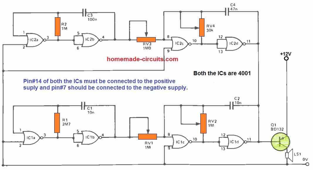
The resistance of the LS1 can range from 8 to 100 Ohms, although below 30 Ohms, the transistor can become rather hot, necessitating the use of a modest heatsink.
Hardly any of the component values are crucial, and RV1,RV3 may be substituted with fixed resistors without having a significant impact on the range of sound effects.
Simple Crossover Network Circuit for Loudspeakers
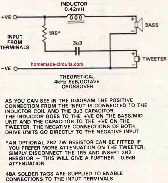
This is a basic 6 dB / octave crossover network, adjusted to work at 4 kHz. It uses an inductor choke in the lower frequency section in order to enable bass / mid roll-off, along with a resistor and capacitor in the tweeter section.
The resistor balances out a minor inefficiency between the two sections by attenuating the tweeter and lowering its output by -1.4 dB, while the capacitor safeguards the tweeter.
The crossover uses high-quality air cored inductors and polyester capacitors since they directly affect the final sound quality.
Another benefit of simple crossover networks is that the fewer components employed, the less system inefficiencies there will be in the future.
The finished system has a high efficiency rating of 88.6 dB SPL at 1 meter / 1 watt, meaning it produces more output per watt than previous, less efficient systems.
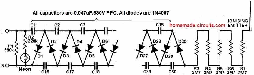
Room Ionizer Circuit
A room ionizer circuit operates by creating a significant potential difference (voltage) between electrodes using a high-voltage setup, frequently utilizing a Cockroft Walton ladder network. Ions are created in the air as a result of the corona discharge caused by this voltage.
These ions attach themselves to dust or allergens in the air, making them charged as a result. The charged particles are then drawn to surfaces with opposing charges, thereby purifying the air of them and perhaps even enhancing it.
How the Circuit Works
This hobby circuit setup incorporates a standard Cockroft Walton ladder network, which constitutes the core of the room ionizer circuit.
This arrangement is devised to amplify the mains voltage, raising it to around -10kV (open-circuit voltage).
The fundamental principle involves cyclically transferring charge between two rows of capacitors during each mains cycle, progressively elevating the voltage along the chain due to the rectifiers' functioning. The primary objective is to create an effective room ionizer.
Once all capacitors are completely charged, theoretically, each capacitor should maintain a voltage equivalent to the peak-to-peak mains voltage.
However, the practical performance of this configuration is notably hampered by factors such as leakage and corona discharge.
As a result, achieving the complete voltage output is impeded by these effects.
The slight ionizing current generated in the room ionizer circuit is sufficient to diminish the output voltage to about -4kV, which intriguingly aligns with the optimal output for an air ionizer.
Beyond this voltage level, ozone tends to be produced instead of ions, while significantly lower voltages are insufficient for efficient air ionization.
Remarkably, a simple touch to the emitter point can significantly reduce the voltage output.
Caution
Nevertheless, it is of paramount importance to exercise caution. Although the entire circuit demonstrates a high output resistance, the individual capacitors do not.
Therefore, prudence is imperative during circuit testing.
The capacitors retain their charge for a certain duration after disconnecting the ionizer from the mains AC, and inadvertent shocks are possible when handling the back of the PCB.
Typically, these shocks pose minimal risk to a healthy individual, but those with cardiac issues or pacemakers should refrain from taking any risks.
To discharge the ionizer, briefly touch the ionizing point with the mains plug for a few seconds.
For added assurance, running the mains plug along the diode connections on the PCB can also effectively discharge the ionizer circuit.

Questions & Answers
Can you make a circuit to charge [only] a battery when another battery is fully charged, but the other battery [only] if it is not fully charged?
If both the batteries are rated at the same voltage, then it won’t work, since both will attain equilibrium and never be able to optimally charge each other.
I propose not connecting them in parallel. I would like the circuit to connect to them separately and charge them one-at-a-time, in a specific order.
In that case, you can try the first circuit from the following article:
https://www.homemade-circuits.com/automatic-dual-battery-charger-with/
Can you make a WWVB tuner that uses an Arduino Uno to display the time [and maybe the date] via 7-segment LEDs?
I will try, if possible…
Thanks.
Hej!Letar efter en byggbeskrivning
bldc borstlös fartkontroll för rc modeller när man styr controllen med insignalen 1-2 ms.
Vill bygga en egen med analogiska komponenter.Ej något annat sätt.
Har letat överallt på nätet men inte hittat någon bra beskrivning.Hoppas på hjälp.
Hälsningar Göran
Hey, if you ae trying to build a BLDC driver using analogue components then you can try the last concept from the following article:
https://www.homemade-circuits.com/sensor-less-bldc-motor-driver-circui/
Let me know how it goes…
Thanks for the answer. But the problem is getting a bldc circuit to work with a control of a pulse that varies between 1ms to 2ms
Thanks for your interest. But do you know any rc site that deals with different circuit solutions for home builders. I checked the page “stefanv” he has different esc controllers but only for brushed motors nothing with brushless ones.
You said you wanted to control the BLDC motor with 1ms, 2ms pulse, do you mean you want to switch the motor ON/OFF with this pulse input?
It is a pwm control where the motor stands still for 1 ms. 1.5 ms the motor runs at half speed. 2 ms the motor runs at full speed. The rc structure has that type of signal. The same applies to the rc servos.
Are you referring to PWM duty cycle? If you are trying to control the BLDC motor with PWM duty cycle then I think it is not so difficult.
In that case, unfortunately, I do not have any idea how that can be implemented in a simple BLDC motor driver circuit.
Thank you for explanations. Very well made.
I appreciate Your circuits very much!
Thank you for your kind feedback, glad you liked the circuits.
Hi I am looking for a circuit to build from scratch or add to an existing circuit pulse counter 12vdc 0-99 resolution circuit that will allow me to scale the pulses ie it will count a set number and only update the counter by one.
Hi, sorry, I do not seem to have this circuit in this blog at the moment.
I was just looking at the circuit for testing crystals and thought perhaps an LED would be a better choice for L1 along with a proper Vdrop R ( 330 for a +5Vcc or 270 with a 3.3Vcc) also there isn’t a value given for the cap C4, what is a good value to use here (103 or 104)? Another thing, I was thinking a Vreg would be a good deal to include in this circuit as there is no suggested Vcc shown, maybe a 5 V or a 3.3V reg would be apporopriate with the LED? I haven’t built it yet but will be doing this shortly and use my ideas. If using the LED, the final Q could be almost any NPN such as a 3904.
Yes LED can be used instead of the incandescent lamp. The LED should have an appropriately calculated series resistor with it. C4 is the filter capacitor so can be any value between 1uF and 10uF.
Any small general purpose device can be used for the transistors. All the best to you.
I assembled the crystal tester last night and this morning and it failed. I have gone over all the connections, checked the components to be sure I didn’t cook anything, all is good. I used SMD parts for the small caps, resistors, and used a red SMD LED for a power indicator to show the circuit is powered up because I installed a 7805 between the 9v bat and the collectors of the 2 Q’s. I used 390 R’s in series with the LED’s. The first is a Red down line of the limiter R to the output of the 7805 with the K to ground. The sec. is a green which should have indicated a functioning crystal inserted in the socket grid I installed so I could plug in several different styles of crystal/case. I powered the circuit and checked for voltages and I have ~5v to the top side of the socket where the 33k R is. Now since Arduinos all run either 5v or 3.3v, I figured this would be a good idea to copy. I’ve checked all the diodes and Q’s, no failed parts, I’ve checked and rechecked to see if I had an open somewhere and have found nothing yet, this is a simple circuit for me but it doesn’t work. I’m getting a small V at the base of both transistors which should have turned on the oscillator section. According to the way I’m seeing this circuit, if the crystal is installed with a voltage applied to the one terminal of it than the crystal should start oscillating an generate a signal to the base of Q1 which would pass on to Q2 which is coupled via the 820 P cap and half waved to the base of Q2 with the 4.7 cap I used as the filter to keep the base of Q2 switched on which isn’t happening, I know it will turn on because while I was working with the circuit, I could get it turn on and stay on briefly by finger contact on the back side of the board and the LED would light up and dim slowly after removing my finger. I have installed a couple of crystals and get the same results. Adjusting the 10k doesn’t change anything. I used 2n3904’s for both Q’s maybe this is the problem, I’m not an EE, just a hobbyist but as you mentioned any Q should have worked along with the LED in series with the Q’s and proper resistors, all that is needed is for the crystal to oscillate to drive the first Q and the circuit should run as long as a good crystal is there. I didn’t have any 820 P caps but I was able to get a stack of SMD pieces on the board and checked the capacitance, a combination of 3 got me to within less than 10 P of the shown values for 1 and dead on for the other. If you have any ideas or suggestions they would be great help. I purchased one of those cheap PIC driven DIY kits on Ebay a while back that was supposed to display the freq of the crystal if it was functional on an array of 7 seg LED’s but it displayed some giberish that mad no sense for about 5 minutes and died. Next month I’m going to order another digital LDC display for counting freq to use with my HAM projects and some other stuff because I really need a working crystal tester along with some other stuff. In the meanwhile, I’m going to look at some other posts to see if there is a tester with a counter or whatever to try to see if I can get a working tester. I’ll wait and look forward to hearing from you on this project and hopefully some suggestions. Sorry this didn’t work for me as I have used a lot of you stuff over the years and had pretty good success. I’ve done 2 of the 555 based zener tester circuits so far and both worked fine, the last one I used a different switch arrangement, tactiles instead of toggles both for power and voltage and load, this is the circuit that uses the little audio Xformer, it was a bit of a search to find this time. I’m not sure where I find all the stuff I have assembled so far but I do search your site for a lot. Again I hope we can figure out what is holding this back.
Thank you Bret,
I right side transistor of the crystal tester is wrongly shown as 8550. The 8550 is a PNP transistor which is incorrect, it should be a NPN.
Since an LED is being used, both the transistors can be BC547.
Also the base capacitor of the right side transistor should be very small in value. The 1uF and 10uF value suggested by me is incorrect.
I have a dedicated article on a crystal tester circuit which shows all the part numbers in details. You can check it out here:
Simple Crystal Tester Circuit
My reasons for coming here? Hello again, this is me, Bret, I just wanted to send a message to you because you have always been fast at replying to anything I posted to you. For now, I’m working at building a circuit I found online that seems to have been taken over by new owners and it is rather old. I found this by accident but when I looked at it I figured this is something I should have in my box of tricks, test equip. etc… The circuit is for a low distortion audio sig gen found @ 4qdtec.com/singen.html — In this circuit there is a glass beaded thermistor and I do not have any of these critters, though I could rig something up but what value and would it be a neg or pos. temp coef. ? If you have a bit of time would you look for and at the circuit and see if you have any advice for me? I’m going ahead with the build as I’m already a ways into it and will leave the part open for later if and when I get any input on it. Thank you for your continued association with me and all the things you have done for everyone so far. I find your pages so helpful on so much. Perhaps you have already done something in this catagory and I just haven’t found it yet.
Thank you Bret,
I checked the circuit, it looks OK to me, so you can go ahead and build it. All the best to you! I haven’t tried any such circuits so far! Let me know the results once you build it.
Hi Swagatam,
Could you please explain the Simple Water Level Alarm Circuit? I do not understand how the PNP and NPN transistors are connected. I am newbie and I have only seen the transistors connected to a + and -. But in this case, the connection to the Speaker are not clear. I also understand that the Speaker has no polarity but I am not able to follow the connections between the transistors and the speaker.
Hi Vijay,
I have provided the explanation just below the water level indicator circuit diagram. You can check it out.
Hi Swagatam, Thanks for the reply. A follow up question is that usually I have see the Collector of the PNP transistor connected to the ground/negative. In the schematic, why is the Collector of the PNP connected to a speaker terminal which is connected to the ‘+’ of the power supply. The Collector of the NPN transistor is correctly connected to the ‘-‘ of the power supply.
Hi Vijay,
The collector of a PNP transistor is normally connected with the load and then ground, not with the ground directly, unless of course the load is connected with the emitter of the transistor. The same has been done in the water level circuit as well.
The PNP behaves exactly opposite to an NPN. In a NPN transistor the load is connected with the positive supply and collector of the transistor, for a PNP the load is connected with ground and the collector of the transistor….just the supply polarity for the load changes.
Hi Swagatam, I understand the explanation but I am afraid I cannot relate to the scematic.
Hi Vijay, In the water level circuit the collector of the PNP is connected to one wire of the speaker and the other wire of the speaker is connected to ground of the supply. So the load is always connected between the ground and the collector for a PNP transistor.
Thank you!
Vďaka za rôzne zaujímavé schémy obvodov.
Thanks, and glad you liked them!
Please send me your contact information via email. Thanks, Debebe Asefa
You can ask your question here through comments, If it is possible I will try to solve it for you.
i want to make a 60v or 48v battery charger, just a simple scheme, i have 24v x2 -0 transformer 6amps, 4 pcs. diode 6A05, 2pcs. capacitor 7400uf 50v. I hope you can give me a cheme, i am learning to make some electronics hobbyest. thank you
Engr. Ronnie rey Canete BS Ae E.
You can try building the following simple design for charging your 48V battery:
You can replace the transformer with your 48V transformer and the bridge rectifier diodes with the diodes available with you. The filter capacitor may not be required.
Select the zener diode such that the output voltage at the emitter of TIP35 is around 56V
i had already make it sir thank you. I can charge now my etrike 60vdc,
Sure, no problem, all the best to you!
good afternoon, How to make a power supply 12volts using 18v -0- 18 Tranformer. What are the scheme and parts to install. Thank you.
You can use the 0-18V wires of the transformer, connect bridge rectifier and a filter capacitor to it. Then after the filter capacitor you can add a 7812 IC for getting the 12V output….if you want the schematic let me know I will help.
Hi Swagatam
Nice circuits in this blog
In your article SIMPLE LED FLASHER , one diagram show is for two leds fkashing alternating
Little further down in the article you mention about multiple leds in series /parallel with the parts list but there is no diagram shown
Kindly check this out and add the diagram may have been left out by mistake
I know how it should be but for other viewers
Regards
Vee
Thank you very much Vee, for notifying about the missing diagram. I have updated the new diagram for your reference, and for the other visitors..
Hi Swagatam
I have gone through the various circuits in this article/blog and find them AMAZING.
In the water level alarm circuit I built one a little similar to this and added a relay additionally which turns off the motor of the water pump when the water tank is full.
To switch on the motor again I used a latching circuit with a PUSH BUTTON to trigger the relay ON and so does the water pump motor.
You can add this to that article if you want to
Regards
Vee
Thank you very much Vee,
Yes I would love to add it to this compilation.
Please send it to my email address.
Dear Swagatam,
In this pandemic measuring oxygen level is a must, also doctors need to see the respiratory rate.
My daughter had covid and the doctor asked for the respiratory rate, the only way was to visually measure by the rise and fall of chest, but this could be inaccurate.
I was working in medical electronics way back in 70’s and manufacturing multi channel recorders. In this we were also recording respiration by using a thermistor and IC 741 to amplify. The thermistor was kept in front of the nose and the principle was simple, exhaling out warm air and inhaling cool air of the atmosphere would be sensed by the thermistor probe and the signal was amplified and recorded in wave form. giving high and low.
Now I was wandering is this can be used to count the highs and display the reading on digital meter as respiration per minute.
Now I am 73 yrs and doing hobby projects at home. It has been ages since I left medical electronics and switched to finding oil and maintenance of equipment used in oil exploration.
Request you to help me to make this project.
Thanks
Dear Ashok, I think you can try modifying the following circuit which looks related to your specific requirement:
https://www.homemade-circuits.com/make-this-thermo-touch-operated-switch/
The point C could be integrated with any two digit counter circuit such as the following:
https://www.homemade-circuits.com/0-to-99-digital-pulse-counter-circuit/
In the above circuit the pin2 of IC1 could be connected with the point C of the thermo circuit.