The following post discusses a simple hum filter circuit which can be installed between an audio input source and a power amplifier, so that any possible mains hum frequency within the audio signal is blocked and only the clean audio frequency is allowed to go through.
Introduction
As the name suggests, hum noise is in the form of a disturbing low volume humming sound that is caused due to the 50 Hz or 60 Hz mains frequency leaked into the DC power supply from the mains AC line. Since this hum runs into the DC supply lines it easily gets induced into an associated input audio signal.
When this audio signal is amplified by a power amplifier, the hum noise also gets proportionately amplified generating an undesirable and annoying hum sound into the amplified audio output, from the amplifier.
By employing a notch filter at the hum frequency of 50 Hz, the proposed hum filter circuit tries to solve some of the difficulties associated with mains-induced hum noise.
Any existing audio signal will be muted at this 50 or 60 Hz mains frequency. The response would revert to the unattenuated input level at frequencies on either sides of the notch.
The bandwidth, or narrowness, of the amplitude response of a tuned circuit - that the RC structure in this circuit produces, is determined by the 'Q', or Quality Factor.
The Q of this circuit dictates the narrow structure of the notch since the circuit is designed to work like a specialized notch filter.
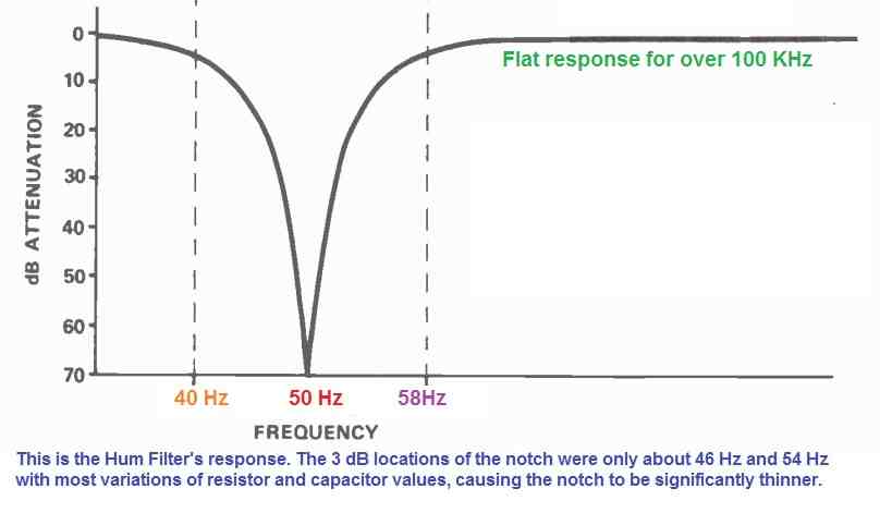
The frequency response of this hum filter circuit circuit will rapidly collapse around the notch frequency through a high -Q notch. Frequencies a bit to the left and right of the notch center frequency would remain unaffected. Frequencies on both sides of the notch frequency would be muted in case the Q is low.
With a high-Q circuit, the real attenuation at the notch frequency is larger than with a low-Q circuit. The downside of high-Q circuits is that little variations in part values, such as those caused by temperature fluctuations, will impact the center frequency.
The circuit's frequency tuning is also very crucial. Circuits with a smaller-Q suffer less from this drawback. The Q used for this hum filter circuit was a balance between vital tuning and drifting effect requirements, as well as a strong notch attenuation with minimal influence on the remaining frequencies.
Maximum attenuation at the notch center frequency of 50 Hz is roughly 80 dB, but at 40 Hz and 58 Hz, attenuation is just 3 dB. You may find some audible influence on a system's bass response, although it is minor.
How the Circuit Works
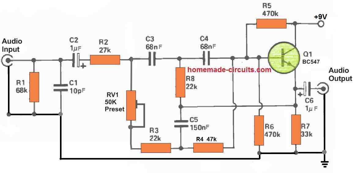
A "Twin -T" notch filter is constructed using capacitors C3, C4, and CS, as well as resistors R3, R4, R8, and preset PR1. The condition C3 = C4 = C5 / 2 is necessary for the Twin -T to function correctly.
Also, for the resistors, it is required that R3 + PR1 = R4 = 2R8
If a nice, deep notch filter is to be developed, the above parameters should be satisfied with reasonable precision. The preset compensates for part value mismatches to some extent and anticipates that the notch may be tuned to the precise hum frequency that needs to be cancelled. The notch's frequency is then determined by the formula:
f = 1 / 2πR4C4
The transistor is set up as an emitter follower, which means it has no voltage gain but provides feedback to the notch to enhance the Q to reasonable limits.

Need Help? Please Leave a Comment! We value your input—Kindly keep it relevant to the above topic!