The IC LM 339 is primarily created to compare two input voltages and generate a corresponding output. Having said that, before we try to learn regarding the various LM339 based circuits, it would be important to go through the standard features of the LM339.
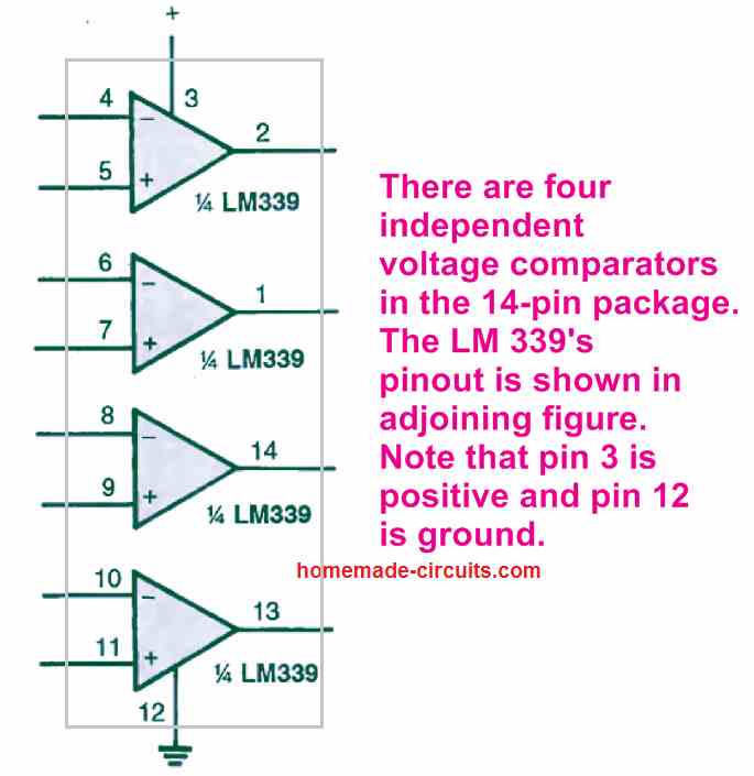
It is basically a quad comparator IC, meaning we can find four numbers of individual voltage comparators in a single 14-pin package of LM339 IC. These comparators are built to work from a single dual voltage supply source, which can be anywhere of 2 V to 32 V. The quiescent current drain of the IC is incredibly low (generally under 1 mA) and it is not dependent on the supply voltage input.
The input voltage supplied to the input pins of the IC LM339 could be as high as the supply voltage. The output of he IC is an open NPN collector and is designed to tolerate a short circuit to ground without getting damaged.
The pinout of the IC LM 339's pinout can be seen in the figure below. Observe that pin 3 is the positive input supply pinout while pin 12 is the ground supply pinout of the IC.
Non-Inverting Comparator
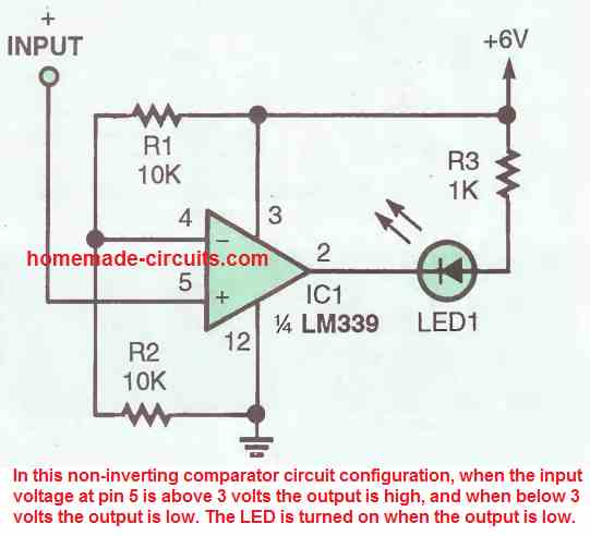
In the next figure above we can find how the IC LM339 can be configured as a non-inverting comparator-circuit . The inverting input pin4 of the fixed with 3V reference by the voltage divider network formed by R1, R2. As long as the potential at pin 5 stays over 3 volts the output stays high, and the moment it drops below 3 volts the output of the IC turns low.
Remember, normally this should have caused the output to become high, but in IC LM339 the output turns low because of the internal transistor which inverts the response for the output of the IC.
The above condition causes the LED at the output to switch ON due to a low logic from the IC output.
Inverting Comparator
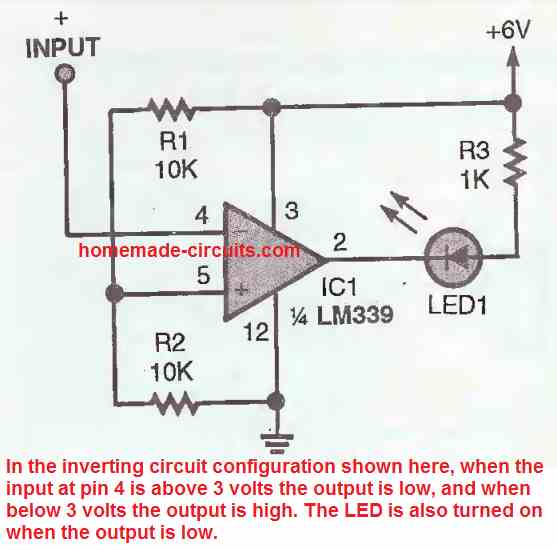
An LM339 inverting comparator circuit diagram can be witnessed in the figure above. Here pin5 of the IC is fixed with a reference voltage of 3 V by the voltage divider formed by R1 and R2.
As long as the potential at pin 4 of the IC is higher than 3 volts, the output of the IC stays low, but the moment it goes below below 3 volts, the output switches to low logic. The condition again causes the LED to switch ON due to the low logic from the IC output.
LM339 Oscillator
The LM 339 comparator circuit can be quickly converted into an oscillator circuit, as indicated in the figure below. Resistor R5 and capacitor C1 work like the RC timing network which determines the frequency the oscillation.
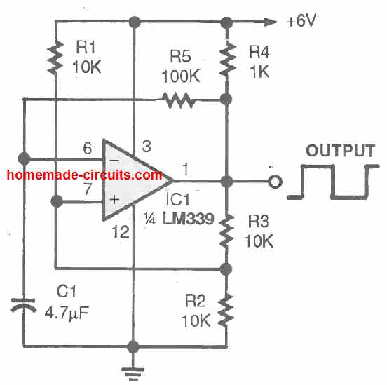
These are selected so that the LM339 circuit oscillates at a frequency of about 1.5 Hz. If you reduce the value of any one of the RC components will cause an increase in the output frequency of the oscillator. If you do the opposite will cause the oscillator frequency to reduce.
Alternate LED Flasher
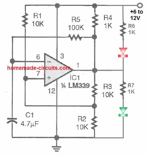
A flashing LED always looks more attractive than a solidly lit ones, and that is precisely what happens if the oscillator circuit is configured as given in the above figure. Here the LEDs oscillate and turn ON/OFF alternately.
LED Strobe Light
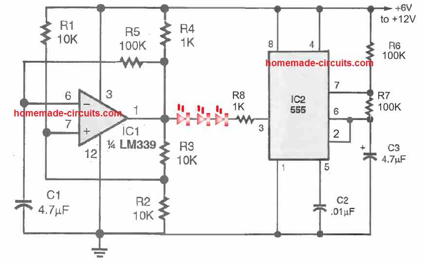
The above IC LM339 circuit can be used to create even more impressive looking LED strobe light blinker which intermittently flashes and then turns OFF, then again turns ON , flashes intermittently and then turns OFF.
This effect is achieved by integrating a IC 555 astable oscillator with the output of the LM339 oscillator circuit.
The LM339 provide the slow ON/OFF square wave pulse to the LED that causes LED to switch ON/OFF at moderately slow erate, while the IC 555 strobes the flashing LEDs into to rapidly switching ON/OFF pulses. The LEDs can be 20 ma high bright RED or white LEDs.
To get a dual color strobe light, you an add another string of LED (green) connected parallel to the RED LEDs but in the opposite direction (reverse polarity).
LM339 Vibration Detector
A very sensitive vibration detector circuit can be built using a single LM339 op amp as shown in the following figure.
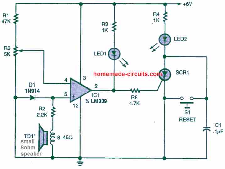
A tiny 8 ohm speaker is used as the vibration sensor while the opamp is configured in the non-inverting comparator mode. When the speaker detect a vibration, it develops a voltage difference at pin5 of the IC that may exceed the reference voltage at pin4 as set by the preset R6. This cause the output of the op amp to go high momentarily, triggering the SCR ON, and the SCR LED lights up indicating the presence of the vibration on the speaker.
Initially when there's no vibration on the speaker, the potential at pin5 of the IC remains lower than the pin4 reference voltage, which causes the output of the opamp to remain low, and the SCR remains switched OFF.
The SCR can be any low voltage low current SCR.
The R6 preset must be set carefully so that the potential of pin4 is hardly 0.3 V higher than the pin5 potential.
Touch Sensor using LM339
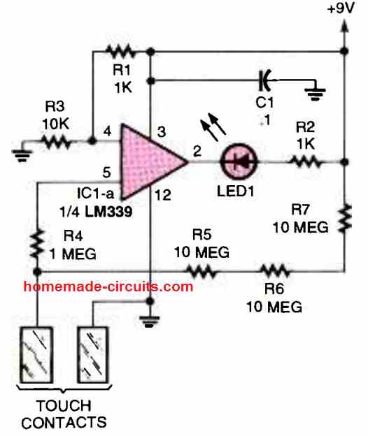
In this touch sensor circuit also, the LM339 opamp can be seen wired in the non-inverting mode. The pin4 of the IC is clamped at some potential which is just lower than the pin5 potential.
Due to this the pin5 potential remains higher than the pin4 potential causing the output pin2 to remain high initially.
The situation causes the LED to remain shut off.
When the indicated touch pads are touched, causes the pin5 voltage to drop below the pin4 voltage, due to the ground potential delivered to pin5 through the finger contacts.
When this happens, the output of the op amp quickly turns low, and the LED gets the required ground potential for illuminating and indicating the existence of a touch contact on the touch plates.
So these a few LM339 circuits that you can build at home, if you have any more similar ideas do let us know through your comments, we will try to update them quickly in the above article.
Universal 4 LED Signal Monitor Circuit
The next design below shows how a single LM339 IC can be used to monitor a signal level through a 4 LED bar graph circuit.
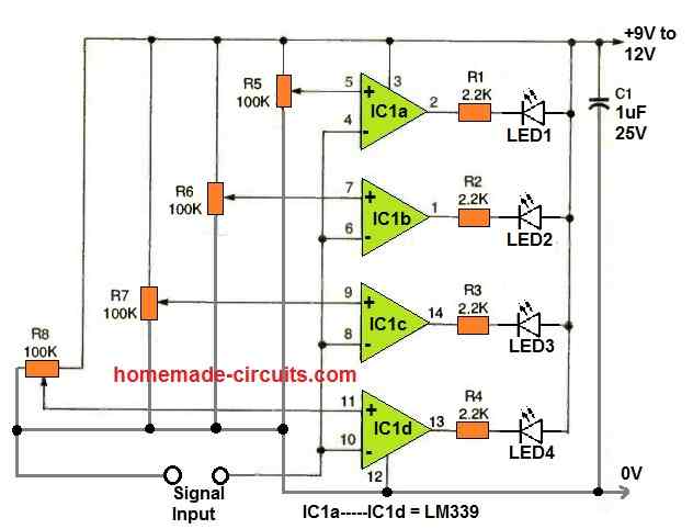
As can be seen in the diagram, each of the comparator units from the IC LM339 are individually configured as adjustable comparator circuits.
The adjustable feature is configured with the non-inverting pins of the comparators.
The inverting inputs are all joined in common and used for detecting the input signal level.
Depending on how the 100 K presets are adjusted, the rise and fall of the input signal level is accordingly displayed through the output LEDs in a sequential bar graph manner.
This universal 4 LED bar graph monitor circuit can be used for many applications, as given below:
- For monitoring AC or DC voltage levels.
- For monitoring music level, as VU meter.
- For monitoring battery charging levels.
Window Comparator
Window comparator is an arrangement where two comparators are used to control the upper and lower limits of the input signal. The outputs of the two comparators become active alternately whenever the input signal tries to cross the set upper or the lower limit.
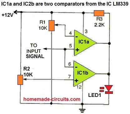
The above circuit operates as a window comparator circuit by utilizing two portions of a quad LM339 comparator.
The signal input stage is made up of the non-inverting input of one comparator and the inverting input of the other. The remaining two inputs of the comparators are coupled to resistors R1 and R2.
R1 and R2 are two ten-turn potentiometers, configured to set the upper and the lower reference voltage limits for the two comparators. The outputs of the two comparators are joined together and is used to operate the LED1.
How to Set up
The simplest approach to setup the window circuit is to use a digital voltmeter to adjust the reference voltages using R1 and R2 to the same voltage. Next, simply vary one of these pots to determine the maximum window width.
LED1 will remain switched ON as long as the the input voltage signal is within the set window limit. Because of the sensitive nature of the design, it is possible to setup the window width to just to a few millivolts or, if you wish, keep it wide open upto many volts.
Mains AC Voltage Monitoring Circuit using LM339 and Arduino with LCD Display
So here we are trying to make one circuit that can detect voltage fluctuation happening in three phase line or single phase line and then show the condition on lcd display in real time.
We are doing this because sometimes that mains voltage is going too high or too low which is not good for sensitive machine or equipment like teleferico motor or any controller.
So that we want to detect this condition fast and see on lcd and maybe take some step for maintenance or alarm or shutdown.

Main working idea
We are using one step-down transformer that will take that high voltage of 430 volt or 440 volt or whatever and bring down to some low level like maybe 12 volt ac or something which is safe for using in our electronics circuit.
But we are not measuring that voltage directly using Arduino analog pin because that is not so accurate and little risky also.
Instead we are using voltage comparators which will tell us whether the voltage is below one minimum level or above one maximum level.
Then Arduino will just check the output of those comparators and show message on lcd display.
Voltage Reference Setup using LM339
Now we are using one LM339 quad comparator ic. Inside that ic there are four separate comparators which we can use.
But for now we are using only two comparators. We set one comparator to detect low voltage and another one to detect high voltage. For example, we are assuming that normal voltage should stay between 370 volt and 470 volt.
So when that transformer output is stepped down, then we get maybe 12 volt when real line is 430 volt. So we can use one resistive voltage divider network and adjust it such that when actual mains is 370 volt, that divided voltage is for example 1.5 volt dc, and when it is 470 volt then the divided voltage becomes 2.2 volt dc.
We give this divided voltage to the non-inverting pin of the lm339 comparator. Then we give fixed reference voltage from one adjustable potentiometer to the inverting pin.
In first comparator we set that reference to 1.5 volt. So when mains voltage drops below 370 volt, then that divided voltage drops below 1.5 volt and comparator output goes low. In second comparator we set the reference to 2.2 volt.
When mains goes above 470 volt then divided voltage goes above 2.2 volt and comparator output again goes low.
Connection to Arduino
So now we connect those two outputs of the lm339 comparator to Arduino digital pins like pin 2 and pin 3. Now when any voltage fluctuation happens, like voltage going below 370 or going above 470, then corresponding comparator will give low output which is detected by Arduino.
LCD display connection
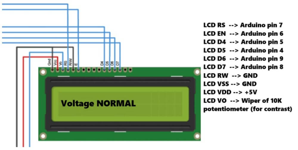
Now we connect one 16x2 lcd display to Arduino using 4-bit mode. So we connect RS, enable and d4 to d7 pins to any Arduino pin. In our code we are using pin 7,6,5,4,9,8.
We can change that if needed. We also connect one 10 kilo ohm potentiometer to adjust lcd contrast.
Arduino logic
In Arduino code, we check those comparator input pins. If undervolt pin becomes low then we show voltage low on lcd. If overvolt pin becomes low then we show voltage high. And if both pins are high, then that means voltage is normal, so we show voltage normal.
Arduino Code
#include <LiquidCrystal.h>

// LM339 comparator output pins connected to Arduino
const int underVoltPin = 2;  // Output from LM339 for <370V
const int overVoltPin = 3;   // Output from LM339 for >470V

// Initialize LCD: (rs, en, d4, d5, d6, d7)
LiquidCrystal lcd(7, 6, 5, 4, 9, 8);

void setup() {
  pinMode(underVoltPin, INPUT_PULLUP);
  pinMode(overVoltPin, INPUT_PULLUP);

  lcd.begin(16, 2);
  lcd.print("Voltage Monitor");
  delay(2000);
  lcd.clear();
}

void loop() {
  bool isUnder = digitalRead(underVoltPin) == LOW;
  bool isOver = digitalRead(overVoltPin) == LOW;

  lcd.setCursor(0, 0);
  lcd.print("Status:          ");

  lcd.setCursor(0, 1);
  if (isUnder) {
    lcd.print("Voltage LOW      ");
  } else if (isOver) {
    lcd.print("Voltage HIGH     ");
  } else {
    lcd.print("Voltage NORMAL   ");
  }

  delay(500);
}
Final testing
After connecting everything, we apply mains to the transformer input and check the lcd display. We can adjust the reference voltages using potentiometer so that it matches the 370 and 470 volt level correctly after dividing through voltage divider.
We must take care that transformer and voltage divider do not give voltage more than 5 volt to the comparator or Arduino.
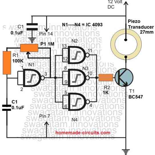
Optional addition
If we want then we can also connect one piezo buzzer or relay to arduino and turn on some alarm when voltage goes too high or low. We can also save the event in eeprom if we want to log it later.
Conclusion
So like this we can make one simple but useful voltage fluctuation detection circuit using one lm339 comparator, one Arduino, one 16x2 lcd, and some resistor, transformer and potentiometer.
This type of project can be used in places where voltage fluctuation is damaging machines again and again like in teleferico system in Merida Venezuela. This will help in monitoring and fast maintenance action.

Questions & Answers
Pueden ayudarme a crear un circuito detector de fluctuaciones con el lm339.. Voltaje iniciall 370 V y el final 470
Please explain the full working description of your circuit so that I can design it correctly…
Objective of the circuit
To detect and visualize voltage fluctuations in an electrical network in order to prevent damage to sensitive equipment, facilitate monitoring, and support maintenance decisions.
Main components
LM339 Comparators: Detect voltage variations with respect to reference levels… 370 volts and 470 volts.
Arduino Uno: Processes the signals from the comparators and handles the control logic.
16×2 LCD Display: Shows the voltage status in real time (normal, high, low).
Transformer: Adapts the mains voltage to a level that can be safely measured. In this case, it would be: (L1 and L2 = 430 volts), (L2 and L3 = 440 volts), (L3 and L1 = 432 volts).
Resistors and Potentiometers: Adjust the reference levels for the comparators.
Working principle
The transformer steps down the mains signal to a level compatible with the circuit.
The signal passes through the LM339 comparators, which compare it with preset voltage limits: minimum 370 volts and maximum 470 volts. If there is a deviation (for example, it exceeds the upper limit or drops below the lower limit), the comparator activates an output.
The Arduino receives this signal and displays a message on the LCD screen indicating the type of fluctuation.
Optionally, an alarm can be triggered or events can be logged for later analysis.
Sorry… the purpose of this is to present a project related to the explanation I just gave, for a problem that is constantly occurring in the Mérida-Venezuela cable car system.
OK, I have updated the full circuit design with explanation at the bottom of the above article, please check it…
OK, let me figure it out, then i will try to design it for you…
How can I replace a 2N3819 based VCR (voltage controlled resistor) with a 2N7000 based one, is it possible or is there any component to replace such and act in the same capacity. The reason I am asking is that there’s scarcely any JFET in my locality and I need a replacement for this component in many circuits I find. Mind you I am relatively new to practical electronics.
Sorry, No, not directly. Because, 2N7000 cannot give smooth resistance control like 2N3819. Gate control of 2N7000 is not like JFET, its not linear. 2N7000 behaves more like a digital switch, not like a resistor.
It is hard to use MOSFET as analog resistor in practical experiments…
Bonsoir. Franchement vos articles sont très instructifs même pour les ignorants en électronique que nous sommes.
Cependant voudriez vous m’indiquer quel circuit intégrer qui peut être équivalent au lm339 svp?
Thank you Jiseph, Glad you liked my circuits and the presentations.
Unfortunately there’s no easy alternative for the LM339 quad comparator IC, so you may have to look for this IC only for these projects.
I have a bunch of toaster control boards surplus in house they contain 4kz ceramic res, 12v 120v transformers, lm339 opamps ,10k pots, lots of diodes and trans etc led, relay motorola microprocessor have probably 400 downsizing willing to sell cheap source of parts
I hope you get a buyer for your components.
Hello Sir,
can you publish a hi/low mains ac voltage cut off circuit using LM393 ic with adjustable power on time delay circuit ,all line in and out led indications taken from the ic circuit only not from the relay contacts and also I want the load output taken from the nc (when the rly in in the off condition .All your circuits published are excellent and good working circuits , i prefer LM393 ic because it is a compact dual voltage comp with hi working voltages ,I prefer you using this ic with a single power supply. voltage range 180 low hi 260vac.
Regards Sambath
Hello Sambath,
You can try the following circuit. You can use an LM358 instead of LM393 in this circuit. LM358 is also very compact, and can work with 32V DC, single power supply:
https://www.homemade-circuits.com/mains-ac-home-protector-circuit/
Let me know if you have any further questions.
Hello Sir,
I would like to communicate with you, pl. give your email address and mob. number.
Thanks & regards,
Akhil
Hello Akhil,
I can discuss only through this website, personal communication may not be possible.