Simple solar charger circuits are small devices which allow you to charge a battery quickly and cheaply, through solar panels.
A simple solar charger circuit must have 3 basic features built-in:
- It should be low cost.
- Layman friendly, and easy to build.
- Must be efficient enough to satisfy the fundamental battery charging needs.
In this post I will comprehensively explain nine best yet simple solar battery charger circuits using the IC LM338, transistors, MOSFET, buck converter, etc which can be built and installed even by a layman for charging all types of batteries and operating other related equipment
Overview
Solar panels are not new to us and today it's being employed extensively in all sectors. The main property of this device to convert solar energy to electrical energy has made it very popular and now it's being strongly considered as the future solution for all electrical power crisis or shortages.
Solar energy may be used directly for powering an electrical equipment or simply stored in an appropriate storage device for later use.
Normally there's only one efficient way of storing electrical power, and it's by using rechargeable batteries.
Rechargeable batteries are probably the best and the most efficient way of collecting or storing electrical energy for later usage.
The energy from a solar cell or a solar panel can also be effectively stored so that it can be used as per ones own preference, normally after the sun has set or when it's dark and when the stored power becomes much needed for operating the lights.
Though it might look quite simple, charging a battery from a solar panel is never easy, because of two reasons:
The voltage from a solar panel can vary hugely, depending upon the incident sun rays, and
The current also varies due to the same above reasons.
The above two reason can make the charging parameters of a typical rechargeable battery very unpredictable and dangerous.
UPDATE:
Before delving into the following concepts you can probably try this super easy solar battery charger which will ensure safe and guaranteed charging of a small 12V 7 Ah battery through a small solar panel:
Parts Required
- Solar Panel - 20V, 1 amp
- IC 7812 - 1no
- 1N4007 Diodes - 3nos
- 2k2 1/4 watt resistor - 1no
That looks cool isn't it. In fact the IC and the diodes could already resting in your electronic junk box, so need of buying them. Now let's see how these can be configured for the final outcome.
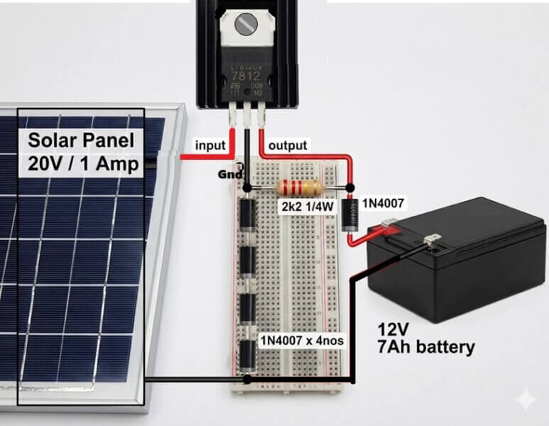
As we know the IC 7812 will produce a fixed 12V at the output which cannot be used for charging a 12V battery. The 3 diodes connected at its ground (GND) terminals is introduced specifically to counter this problem, and to upgrade the IC output to about 12 + 0.6 + 0.6 + 0.6 V + 0.6V = 14.4 V, which is exactly what is required for charging a 12 V battery fully.
The drop of 0.6 V across each diodes raises the grounding threshold of the IC by stipulated level forcing the IC to regulate the output at 14.4 V instead of 12 V. The 2k2 resistor is used to activate or bias the diodes so that it can conduct and enforce the intended 2.4 V total drop.
However, due to the presence of another diode at the battery positive side, a 0.6V is removed from the above charging voltage, making the effective charging voltage at 14.4 - 0.6 = 13.8V, which is still quite good for charging a 12V battery, and it also makes sure the battery remains below the over charge limit of 14.4V, and thus avoids the need of an automatic battery charge cut-off circuit.
Audio/Video Representation
Making it Even Simpler
If you are looking for an even simpler solar charger, then probably there cannot be anything more straightforward than connecting an appropriately rated solar panel directly with the matching battery via a blocking diode, as shown below:
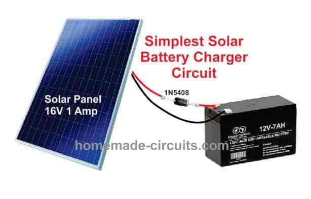
Although, the above design does not incorporate a regulator, it will still work since the panel current output is nominal, and this value will only show a deterioration as the sun changes its position.
However, for a battery that is not fully discharged, the above simple set up may cause some harm to the battery, since the battery will tend to get charged quickly, and will continue to get charged to unsafe levels and for longer periods of time.
You may also like this Highly Efficient 0-50V Solar Charger Circuit
1) Using LM338 as Solar Controller
But thanks to the modern highly versatile chips like the LM 338 and LM 317, which can handle the above situations very effectively, making the charging process of all rechargeable batteries through a solar panel very safe and desirable.
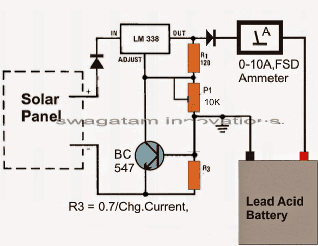
The circuit of a simple LM338 solar battery charger is shown below, using the IC LM338:
Parts List (BOM)
- Resistors
- R1 = 240 ohms 1/4 watt 5% CFR
- R3 = 0.6/Max Battery Charging Current
- P1 = 10k preset
- Diodes are 6A4
- Transistor = BC547
- IC = LM338
- Solar Panel = 18V, 5 Amp
- Battery =12V, 30 to 50 Ah
The circuit diagram shows a simple set up using the IC LM 338 which has been configured in its standard regulated power supply mode.
Using a Current Control Feature
The specialty of the design is that it incorporates a current control feature also.
It means that, if the current tends to increase at the input, which might normally take place when the sun ray intensity increases proportionately, the voltage of the charger drops proportionately, pulling down the current back to the specified rating.
As we can see in the diagram, the collector/emitter of the transistor BC547 is connected across the ADJ and the ground, it becomes responsible for initiating the current control actions.
As the input current rises, the battery starts drawing more current, this build up a voltage across R3 which is translated into a corresponding base drive for the transistor.
The transistor conducts and corrects the voltage via the C LM338, so that the current rate gets adjusted as per the safe requirements of the battery.
Current Limit Formula:
R3 may be calculated with the following formula
R3 = 0.7/ Max Current Limit
PCB Design for the above explained simple solar battery charger circuit is given below:
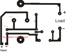
The meter and the input diode are not included in the PCB.
2) $1 Solar Battery Charger Circuit
The second design explains a cheap yet effective, less than $1 cheap yet effective solar charger circuit, which can be built even by a layman for harnessing efficient solar battery charging.
You will need just a solar panel panel, a selector switch and some diodes for getting a reasonably effective solar charger set up.
What is Maximum Power Point Solar Tracking?
For a layman this would be something too complex and sophisticated to grasp and a system involving extreme electronics.
In a way it may be true and surely MPPTs are sophisticated high end devices which are meant for optimizing the charging of the battery without altering the solar panel V/I curve.
In simple words an MPPT tracks the instantaneous maximum available voltage from the solar panel and adjusts the charging rate of the battery such that the panel voltage remains unaffected or away from loading.
Put simply, a solar panel would work most efficiently if its maximum instantaneous voltage is not dragged down close to the connected battery voltage, which is being charged.
For example, if the open circuit voltage of your solar panel is 20V and the battery to be charged is rated at 12V, and if you connect the two directly would cause the panel voltage to drop to the battery voltage, which would make things too inefficient.
Conversely if you could keep the panel voltage unaltered yet extract the best possible charging option from it, would make the system work with MPPT principle.
So it's all about charging the battery optimally without affecting or dropping the panel voltage.
There's one simple and zero cost method of implementing the above conditions.
Choose a solar panel whose open circuit voltage matches the battery charging voltage. Meaning for a 12V battery you may choose a panel with 15V and that would produce maximum optimization of both the parameters.
However practically the above conditions could be difficult to achieve because solar panels never produce constant outputs, and tend to generate deteriorating power levels in response to varying sun ray positions.
That's why always a much higher rated solar panel is recommended so that even under worse day time conditions it keeps the battery charging.
Having said that, by no means it is necessary to go for expensive MPPT systems, you can get similar results by spending a few bucks for it. The following discussion will make the procedures clear.
How the Circuit Works
As discussed above, in order to avoid unnecessary loading of the panel we need to have conditions ideally matching the PV voltage with the battery voltage.
This can be done by using a few diodes, a cheap voltmeter or your existing multimeter and a rotary switch. Ofcourse at around $1 you cannot expect it to be automatic, you may have to work with the switch quite a few times each day.
We know that a rectifier diode's forward voltage drop is around 0.6 volts, so by adding many diodes in series it can be possible to isolate the panel from getting dragged to the connected battery voltage.
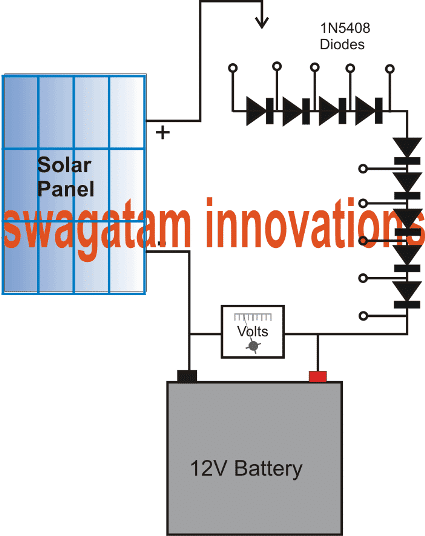
Referring to the circuit digaram given below, a cool little MPPT charger can be arranged using the shown cheap components.
Let's assume in the diagram, the panel open circuit voltage to be 20V and the battery to be rated at 12V.
Connecting them directly would drag the panel voltage to the battery level making things inappropriate.
By adding 9 diodes in series we effectively isolate the panel from getting loaded and dragged to the battery voltage and yet extract the Maximum charging current from it.
The total forward drop of the combined diodes would be around 5V, plus battery charging voltage 14.4V gives around 20V, meaning once connected with all the diodes in series during peak sunshine, the panel voltage would drop marginally to may be around 19V resulting an efficient charging of the battery.
Now suppose the sun begins dipping, causing the panel voltage to drop below the rated voltage, this can be monitored across the connected voltmeter, and a few diodes skipped until the battery is restored with receiving optimal power.
The arrow symbol shown connected with the panel voltage positive can be replaced with a rotary switched for the recommended selection of the diodes in series.
With the above situation implemented, a clear MPPT charging conditions can be simulated effectively without employing costly devices. You can do this for all types of panels and batteries just by including more number of diodes in series.
3) Solar Charger and Driver Circuit for 10W/20W/30W/50W White High Power SMD LED
The 3rd idea teaches us how to build a simple solar LED with battery charger circuit for illuminating high power LED (SMD) lights in the order of 10 watt to 50 watt. The SMD LEDs are fully safeguarded thermally and from over current using an inexpensive LM 338 current limiter stage. The idea was requested by Mr. Sarfraz Ahmad.
Technical Specifications
Basically I am a certified mechanical engineer from Germany 35 years ago and worked overseas for many years and left many years ago due to personal problems back home.
Sorry to bother you but I know about your capabilities and expertise in electronics and sincerity to help and guide the beginnings like me.I have seen this circuit some where for 12 vdc.I have attached to SMD ,12v 10 watt, cap 1000uf,16 volt and a bridge rectifier you can see the part number on that.When I turn the lights on the rectifier starts to heat up and the both SMDs as well. I am afraid if these lights are left on for a long time it may damage the SMDs and rectifier. I don not know where the problem is. You may help me.
I have a light in car porch which turns on at disk and off at dawn. Unfortunately due to load shedding when there is no electricity this light remains off till the electricity is back.
I want to install at least two SMD (12 volt) with LDR so as soon the light turns off the SMD lights will turn on. I want to additional two similar light elsewhere in the car porch to keep the entire are lighted.I think that if I connect all these four SMD lights with 12 volt power supply which will get the power from UPS circuit.
Of course it will put additional load on UPS battery which is hardly fully charged due to frequent load shedding. The other best solution is to install 12 volt solar panel and attach all these four SMD lights with it. It will charge the battery and will turn the lights On/OFF.
This solar panel should be capable to keeps these lights all the night and will turn OFF at dawn.Please also help me and give details about this circuit/project.
You may take your time to figure out how to do that.I am writing to you as unfortunately no electronics or solar product seller in our local market is willing to give me any help, None of them seems to be technical qualified and they just want to sell their parts.
Sarfraz AhmadRawalpindi, Pakistan
Highly Recommended for you: Solar Chargers using Switching Regulators
The Design
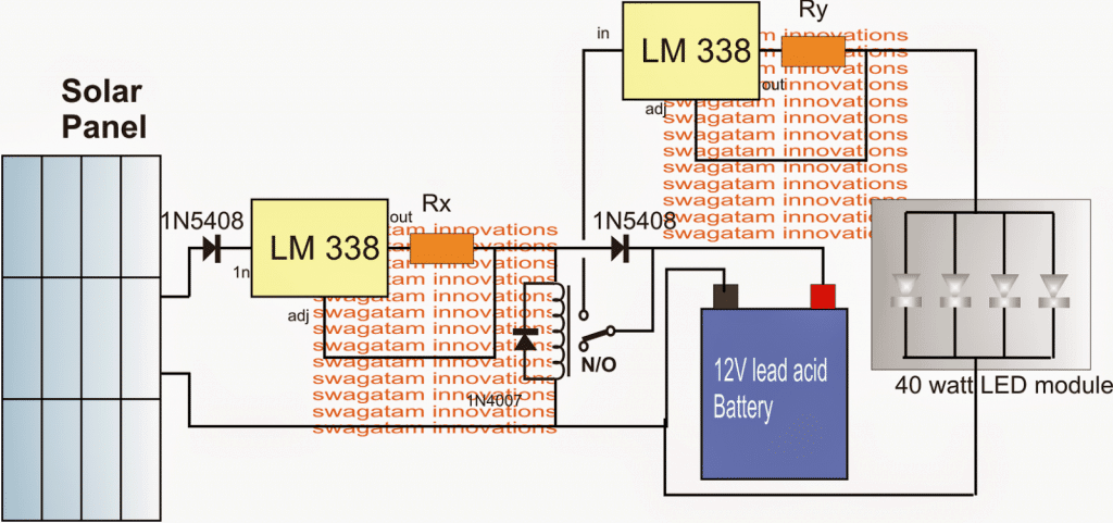
In the shown 10 watt to 50 watt SMD solar LED light circuit with automatic charger above, we see the following stages:
- A solar panel
- A couple of current controlled LM338 regulator circuits
- A changeover relay
- A rechargeable battery
- and a 40 watt LED SMD module
The above stages are integrated in the following explained manner:
The two LM 338 stages are configured in standard current regulator modes with using the respective current sensing resistances for ensuring a current controlled output for the relevant connected load.
The load for the left LM338 is the battery which is charged from this LM338 stage and a solar panel input source. The resistor Rx is calculated such that the battery receives the stipulated amount of current and is not over driven or over charged.
The right side LM 338 is loaded with the LED module and here too the Ry makes sure that module is supplied with the correct specified amount of current in order to safeguard the devices from a thermal runaway situation.
The solar panel voltage specs may be anywhere between 18V and 24V.
A relay is introduced in the circuit and is wired with the LED module such that it's switched ON only during the night or when it's dark below threshold for the solar panel to generate the required any power.
As long as the solar voltage is available, the relay stays energized isolating the LED module from the battery and ensuring that the 40 watt LED module remains shut off during day time and while the battery is being charged.
After dusk, when the solar voltage becomes sufficiently low, the relay is no longer able to hold its N/O position and flips to the N/C changeover, connecting the battery with the LED module, and illuminating the array through the available fully charged battery power.
The LED module can be seen attached with a heatsink which must be sufficiently large in order to achieve an optimal outcome from the module and for ensuring longer life and brightness from the device.
Calculating the Resistor Values
The indicated limiting resistors may be calculated from the given formulas:
Rx = 1.25/battery charging current
Ry = 1.25/LED current rating.
Assuming the battery to be a 40 AH lead acid battery, the preferred charging current should be 4 amps.
therefore Rx = 1.25/4 = 0.31 ohms
wattage = 1.25 x 4 = 5 watts
The LED current can be found by dividing its total wattage by the voltage rating, that is 40/12 = 3.3amps
therefore Ry = 1.25/3 = 0.4 ohms
wattage = 1.25 x 3 = 3.75 watts or 4 watts.
Limiting resistors are not employed for the 10 watt LEDs since the input voltage from the battery is on par with the specified 12V limit of the LED module and therefore cannot exceed the safe limits.
The above explanation reveals how the IC LM338 can be simply used for making an useful solar LED light circuit with an automatic charger.
4) Automatic Solar Light Circuit using a Relay
In our 4rth automatic solar light circuit we incorporate a single relay as a switch for charging a battery during day time or as long as the solar panel is generating electricity, and for illuminating a connected LED while the panel is not active.
Upgrading to a Relay Changeover
In one of my previous article which explained a simple solar garden light circuit, we employed a single transistor for the switching operation.
One disadvantage of the earlier circuit is, it does not provide a regulated charging for the battery, although it not might be strictly essential since the battery is never charged to its full potential, this aspect might require an improvement.
Another associated disadvantage of the earlier circuit is its low power spec which restricts it from using high power batteries and LEDs.
The following circuit effectively solves both the above two issues, with the help of a relay and a emitter follower transistor stage.
Circuit Diagram
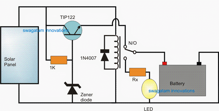
How it Works
During optimal sun shine, the relay gets sufficient power from the panel and remains switched ON with its N/O contacts activated.
This enables the battery to get the charging voltage through a transistor emitter follower voltage regulator.
The emitter follower design is configured using a TIP122, a resistor and a zener diode. The resistor provides the necessary biasing for the transistor to conduct, while the zener diode value clamps the emitter voltage is controlled at just below the zener voltage value.
The zener value is therefore appropriately chosen to match the charging voltage of the connected battery.
For a 6V battery the zener voltage could be selected as 7.5V, for 12V battery the zener voltage could be around 15V and so on.
The emitter follower also makes sure that the battery is never allowed to get overcharged above the allocated charging limit.
During evening, when a substantial drop in sunlight is detected, the relay is inhibited from the required minimum holding voltage, causing it to shift from its N/O to N/C contact.
The above relay changeover instantly reverts the battery from charging mode to the LED mode, illuminating the LED through the battery voltage.
Parts list for a 6V/4AH automatic solar light circuit using a relay changeover
- Solar Panel = 9V, 1amp
- Relay = 6V/200mA
- Rx = 10 ohm/2 watt
- zener diode = 7.5V, 1/2 watt
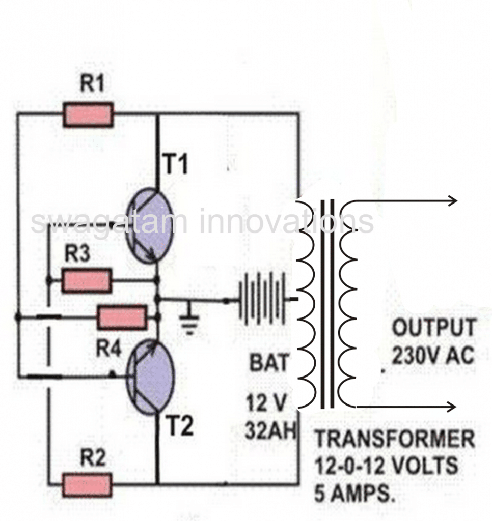
5) Transistorized Solar Charger Controller Circuit
The fifth idea presented below details a simple solar charger circuit with automatic cut-off using transistors only. The idea was requested by Mr. Mubarak Idris.
Circuit Objectives and Requirements
- Please sir can you make me a 12v, 28.8AH lithium ion battery,automatic charge controller using solar panel as a supply, which is 17v at 4.5A at max sun light.
- The charge controller should be able to have over charge protection and low battery cut off and the circuit should be simple to do for beginner without ic or micro controller.
- The circuit should use relay or bjt transistors as a switch and zener for voltage reference thanks sir hope to hear from you soon!
The Design
PCB Design (Component Side)
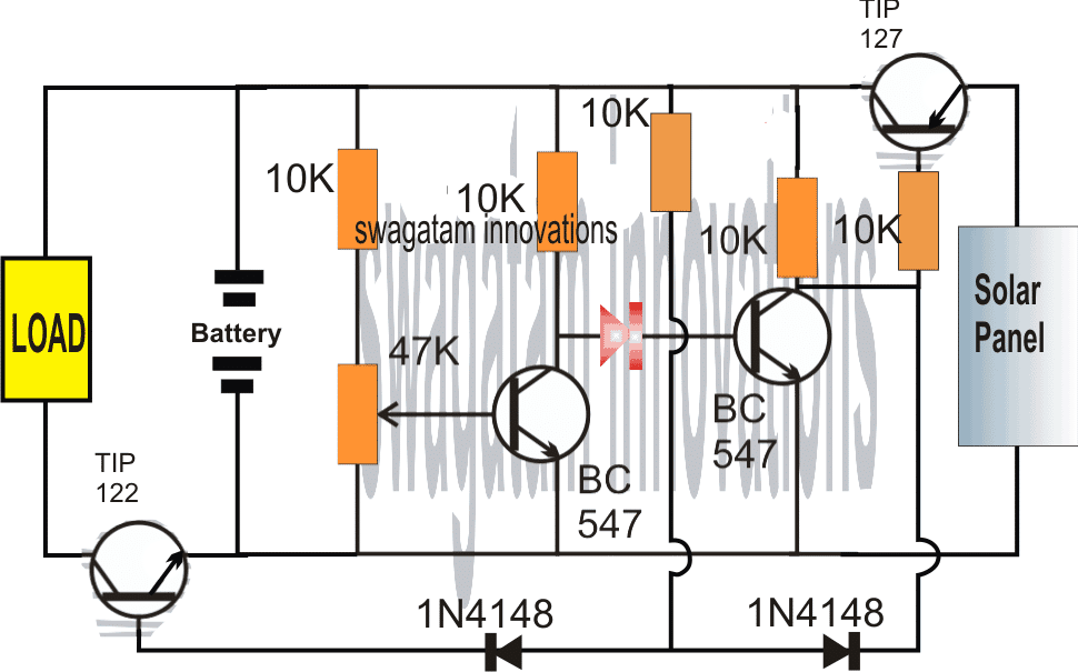
Referring to the above simple solar charger circuit using transistors, the automatic cut off for the full charge charge level and the lower level is done through a couple of BJTs configured as comparators.
Recall the earlier low battery indicator circuit using transistors, where the low battery level was indicated using just two transistors and a few other passive components.
Here we employ an identical design for the sensing of the battery levels and for enforcing the required switching of the battery across the solar panel and the connected load.
Let's assume initially we have a partially discharged battery which causes the first BC547 from left to stop conducting (this is set by adjusting the base preset to this threshold limit), and allows the next BC547 to conduct.
When this BC547 conducts it enable the TIP127 to switch ON, which in turn allows the solar panel voltage to reach the battery and begin charging it.
The above situation conversely keeps the TIP122 switched OFF so that the load is unable to operate.
As the battery begins getting charged, the voltage across the supply rails also begin rising until a point where the left side BC547 is just able to conduct, causing the right side BC547 to stop conducting any further.
As soon as this happens, the TIP127 is inhibited from the negative base signals and it gradually stops conducting such that the battery gradually gets cut off from the solar panel voltage.
However, the above situation permits the TIP122 to slowly receive a base biasing trigger and it begins conducting....which ensures that the load now is able to get the required supply for its operations.
The above explained solar charger circuit using transistors and with auto cut-offs can be used for any small scale solar controller applications such as for charging cellphone batteries or other forms of Li-ion batteries safely.
For getting a Regulated Charging Supply
The following design shows how to convert or upgrade the above circuit diagram into a regulated charger, so that the battery is supplied with a fixed and a stabilized output regardless of a rising voltage from the solar panel.
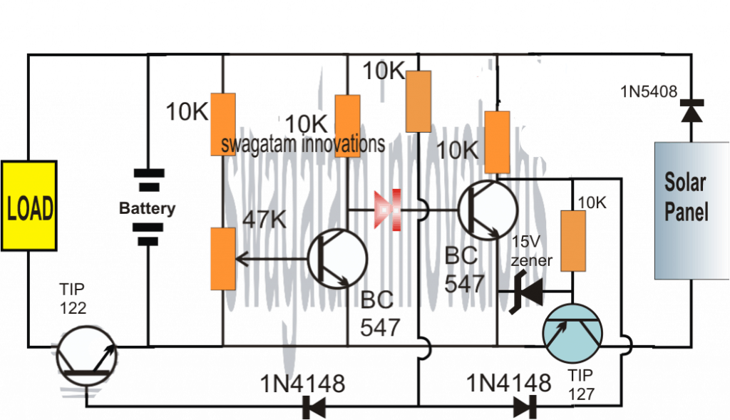
The above designs can be further simplified, as shown in the following over-charge, over-discharge solar battery controller circuit:
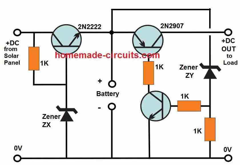
Here, the zener ZX decides the full charge battery cut off, and can be calculated using the following formula:
ZX = Battery full charge value + 0.6
For example, if the full-charge battery level is 14.2V, then the ZX can be 14 + 0.6 = 14.6V zener which can be built by adding a few zener diodes in series, along with a few 1N4148 diodes, if required.
The zener diode ZY decides the battery over-discharge cut off point, and can be simply equal to the value of the desired low battery value.
For example if the minimum low battery level is 11V, then the ZY can be selected to be a 11V zener.
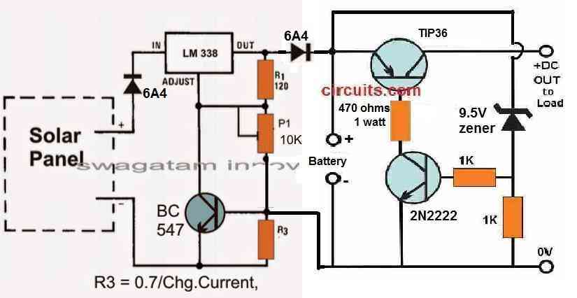
The above design can be also integrated with an LM338 charger circuit as shown below:
6) Solar Pocket LED Light Circuit
The sixth design here explains a simple low cost solar pocket LED light circuit which could be used by the needy and, underprivileged section of the society for illuminating their houses at night cheaply.
The idea was requested by Mr. R.K. Rao
Circuit Objectives and Requirements
- I want to make a SOLAR pocket LED light using a 9cm x 5cm x 3cm transparent plastic box [available in the market for Rs.3/-] using a one watt LED/20mA LEDS powered by a 4v 1A rechargeable sealed lead-acid battery [SUNCA/VICTARI] & also with a provision for charging with a cell phone charger [where grid current is available].
- The battery should be replaceable when dead after use for 2/3 years/prescribed life by the rural/tribal user.
- This is meant for use by tribal/rural children to light up a book; there are better led lights in the market for around Rs.500 [d.light],for Rs.200 [Thrive].
- These lights are good except that they have a mini solar panel and a bright LED with a life of ten years if not more ,but with a rechargeable battery without a provision for its replacement when dead after two or three years of use.It is a waste of resource and unethical.
- The project i am envisaging is one in which the battery can be replaced , be locally available at low cost. The price of the light should not exceed Rs.100/150.
- It will be marketed on not for profit basis through NGOs in tribal areas and ultimately supply kits to tribal/rural youth to make them in the village.
- I along with a colleague have made some lights with 7V EW high power batteries and 2x20mA pirahna Leds and tested them-they lasted for over 30 hours of continuous lighting adequate to light up a book from half-meter distance; and another with a 4v sunce battery and 1watt 350A LED giving enough light for cooking in a hut.
- Can you suggest a circuit with a one AA/AAA rechargeable battery,mini solar panel to fit on the box cover of 9x5cm and a DC-DC booster and 20mA leds. If you want me to come over to your place for discussions i can.
- You can see the lights we have made in google photos at https://goo.gl/photos/QyYU1v5Kaag8T1WWA Thanking you,
The Design
As per the request the solar pocket LED light circuits needs to be compact, work with a single 1.5AAA cell using a DC-DC converter and equipped with a self regulating solar charger circuit.
The circuit diagram shown below probably satisfies all the above specifications and yet stays within the affordable limit.
Circuit Diagram

The design is a basic joule thief circuit using a single penlight cell, a BJT and an inductor for powering any standard 3.3V LED.
In the design a 1 watt LeD is shown although a smaller 30mA high bright LED could be used.
The solar LED circuit is capable squeezing out the last drop of "joule" or the charge from the cell and hence the name joule thief, which also implies that the LED would keep illuminated until there's virtually nothing left inside the cell. However the cell here being a rechargeable type is not recommended to be discharged below 1V.
The 1.5V battery charger in the design is built using another low power BJT configured in its emitter follower configuration, which allows it to produce an emitter voltage output that's exactly equal to the potential at its base, set by the 1K preset. This must be precisely set such that the emitter produces not more than 1.8V with a DC input of above 3V.
The DC input source is a solar panel which may be capable of producing an excess of 3V during optimal sunlight, and allow the charger to charge the battery with a maximum of 1.8V output.
Once this level is reached the emitter follower simply inhibits any further charging of the cell thus preventing any possibility of an over charge.
The inductor for the pocket solar LED light circuit consists of a small ferrite ring transformer having 20:20 turns which could be appropriately altered and optimized for enabling the most favorable voltage for the connected LED which may last even until the voltage has fallen below 1.2V.
7) Simple Solar Charger for Street Lights
The seventh solar charger discussed here is best suited as a solar LED street light system is specifically designed for the new hobbyist who can build it simply by referring to the pictorial schematic presented here.
Due to its straightforward and relatively cheaper design the system can be suitably used for village street lighting or in other similar remote areas, nonetheless this by no means restricts it from being used in cities also.
Main Features of this system are:
1) Voltage controlled Charging
2) Current Controlled LED Operation
3) No Relays used, all Solid-State Design
4) Low Critical Voltage Load Cut-off
5) Low Voltage and Critical Voltage Indicators
6) Full Charge cut-off is not included for simplicity sake and because the charging is restricted to a controlled level which will never allow the battery to over-charge.
7) Use of popular ICs like LM338 and transistors like BC547 ensure hassle free procurement
8) Day night sensing stage ensuring automatic switch OFF at dusk and switch ON at dawn.
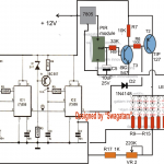
The entire circuit design of the proposed simple LED street light system is illustrated below:
Circuit Diagram
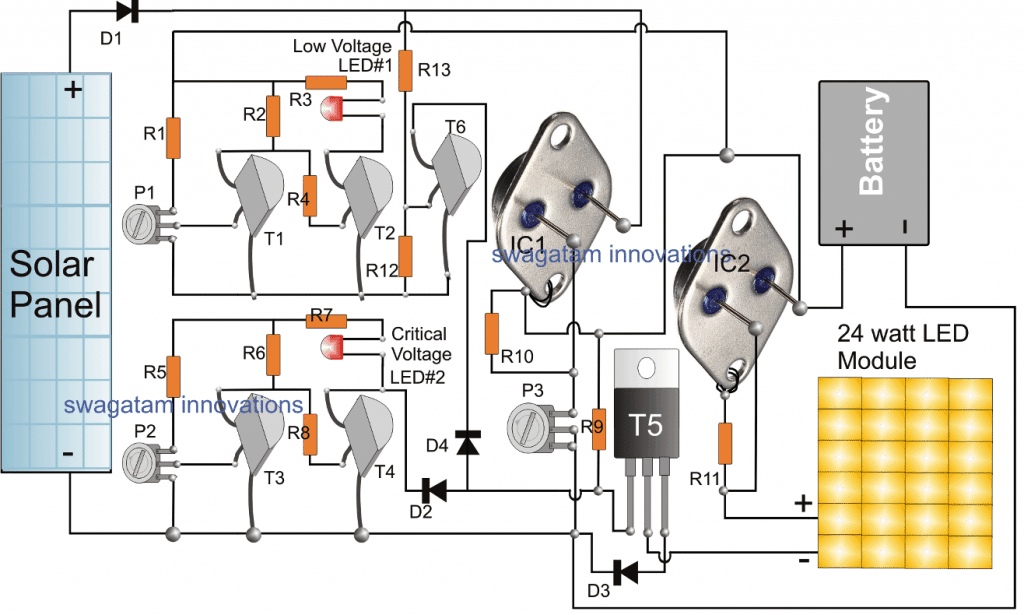
The circuit stage comprising T1, T2, and P1 are configured into a simple low battery sensor, indicator circuit
An exactly identical stage can also be seen just below, using T3, T4 and the associated parts, which form another low voltage detector stage.
The T1, T2 stage detects the battery voltage when it drops to 13V by illuminating the attached LED at the collector of T2, while the T3, T4 stage detects the battery voltage when it reaches below 11V, and indicates the situation by illuminating the LED associated with the collector of T4.
P1 is used for adjusting the T1/T2 stage such that the T2 LED just illuminates at 12V, similarly P2 is adjusted to make the T4 LED begin illuminating at voltages below 11V.
IC1 LM338 is configured as a simple regulated voltage power supply for regulating the solar panel voltage to a precise 14V, this is done by adjusting the preset P3 appropriately.
This output from IC1 is used for charging the street lamp battery during day time and peak sunshine.
IC2 is another LM338 IC, wired in a current controller mode, its input pin is connected with the battery positive while the output is connected with the LED module.
IC2 restricts the current level from the battery and supplies the right amount of current to the LED module so that it is able operate safely during night time back up mode.
T5 is a power transistor which acts like a switch and is triggered by the critical low battery stage, whenever the battery voltage tends to reach the critical level.
Whenever this happens the base of T5 is instantly grounded by T4, shutting it off instantly. With T5 shut off, the LED module is enable to illuminate and therefore it is also shut off.
This condition prevents and safeguards the battery from getting overly discharged and damaged. In such situations the battery might need an external charging from mains using a 24V, power supply applied across the solar panel supply lines, across the cathode of D1 and ground.
The current from this supply could be specified at around 20% of battery AH, and the battery may be charged until both the LEDs stop glowing.
The T6 transistor along with its base resistors is positioned to detect the supply from the solar panel and ensure that the LED module remains disabled as long as a reasonable amount of supply is available from the panel, or in other words T6 keeps the LED module shut off until its dark enough for the LED module and then is switched ON. The opposite happen at dawn when the LED module is automatically switched OFF. R12, R13 should be carefully adjusted or selected to determine the desired thresholds for the LED module's ON/OFF cycles
How to Build
To complete this simple street light system successfully, the explained stages must be built separately and verified separately before integrating them together.
First assemble the T1, T2 stage along with R1, R2, R3, R4, P1 and the LED.
Next, using a variable power supply, apply a precise 13V to this T1, T2 stage, and adjust P1 such that the LED just illuminates, increase the supply a bit to say 13.5V and the LED should shut off. This test will confirm the correct working of this low voltage indicator stage.
Identically make the T3/T4 stage and set P2 in a similar fashion to enable the LED to glow at 11V which becomes the critical level setting for the stage.
After this you can go ahead with the IC1 stage, and adjust the voltage across its "body" and ground to 14V by adjusting P3 to the correct extent. This should be again done by feeding a 20V or 24V supply across its input pin and ground line.
The IC2 stage can be built as shown and will not require any setting up procedure except the selection of R11 which may be done using the formula as expressed in this universal current limiter article
Parts List
- R1, R2, R3 R4, R5, R6, R7 R8, R9, R12 = 10k, 1/4 WATT
- P1, P2, P3 = 10K PRESETS
- R10 = 240 OHMS 1/4 WATT
- R13 = 22K
- D1, D3 = 6A4 DIODE
- D2, D4 = 1N4007
- T1, T2, T3, T4 = BC547
- T5 = TIP142
- R11 = SEE TEXT
- IC1, IC2 = LM338 IC TO3 package
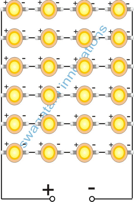
- LED Module = Made by connecting 24nos 1 WATT LEDs in series and parallel connections
- Battery = 12V SMF, 40 AH
- Solar Panel = 20/24V, 7 Amp
Making th 24 watt LED Module
The 24 watt LED module for the above simple solar street light system could be built simply by joining 24 nos 1 watt LEDs as shown in the following image:
8) Solar Panel Buck Converter Circuit with Over Load Protection
The 8th solar concept discussed below talks about a simple solar panel buck converter circuit which can be used to obtain any desired low bucked voltage from 40 to 60V inputs. The circuit ensures a very efficient voltage conversions. The idea was requested by Mr. Deepak.
Technical Specifications
I am looking for DC - DC buck converter with following features.
1. Input voltage = 40 to 60 VDC
2. Output voltage = Regulated 12, 18 and 24 VDC (multiple output from the same circuit is not required. Separate circuit for each o/p voltage is also fine)
3. Output current capacity = 5-10A
4. Protection at output = Over current, short circuits etc.
5. Small LED indicator for unit operation would be an advantage.
Appreciate if you could help me designing the circuit.
Best regards,
Deepak
The Design
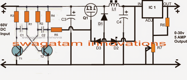
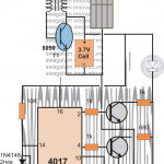
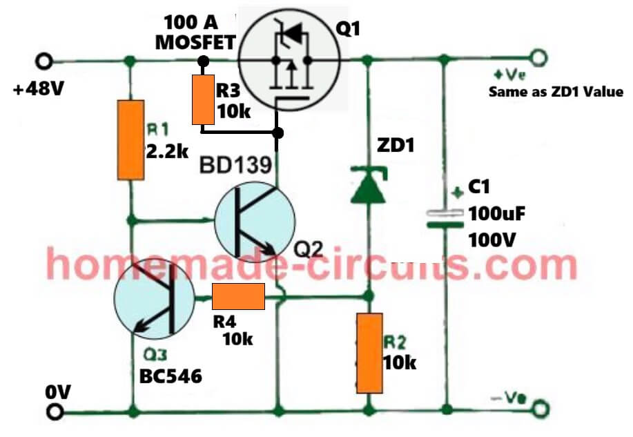
The proposed 60V to 12V, 24V buck converter circuit is shown in the figure below, the details may be understood as I have explained below:
The configuration could be divided into stages, viz. the astable multivibrator stage and the mosfet controlled buck converter stage.
BJT T1, T2 along with its associated parts forms a standard AMV circuit wired to generate a frequency at the rate of about 20 to 50kHz.
Mosfet Q1 along with L1 and D1 forms a standard buck converter topology for implementing the required buck voltage across C4.
The AMV is operated by the input 40V and the generated frequency is fed to the gate of the attached mosfet which instantly begins oscillating at the available current from the input driving L1, D1 network.
The above action generates the required bucked voltage across C4,
D2 makes sure that this voltage never exceeds the rated mark which may be fixed 30V.
This 30V max limit bucked voltage is further fed to a LM396 voltage regulator which may be set for getting the final desired voltage at the output at the rate of 10amps maximum.
The output may be used for charging the intended battery.
Circuit Diagram
Parts List for the above 60V input, 12V, 24V output buck converter solar for the panels.
- R1---R5 = 10K
- R6 = 240 OHMS
- R7 = 10K POT
- C1, C2 = 2nF
- C3 = 100uF/100V
- C4 = 100uF/50V
- Q1 = ANY 100V, 20AMP P-channel MOSFET
- T1,T2 = BC546
- D1 = ANY 10AMP FAST RECOVERY DIODE
- D2 = 30V ZENER 1 WATT
- D3 = 1N4007
- L1 = 30 turns of 21 SWG super enameled copper wire wound over a 10mm dia ferrite rod.
9) Home Solar Electricity Set up for an Off-the-grid Living
The ninth unique design explained here illustrates a simple calculated configuration which may be used for implementing any desired sized solar panel electricity set up for remotely located houses or for achieving an off the grid electricity system from solar panels.
Technical Specifications
I am very sure you must have this kind of circuit diagram ready. While going through your blog I got lost and could not really choose one best fitting to my requirements.
I am just trying to put my requirement here and make sure I understood it correctly.
(This is a pilot project for me to venture into this field. You can count me to be a big zero in electrical knowledge. )
My basic goal is to maximize use of Solar power and reduce my electrical bill to minimum. ( 🙁 I stay at Thane. So, you can imagine electricity bills. ) So you can consider as if I am completely making a solar powered lighting system for my home.
1. Whenever there is enough sunlight, I do not need any artificial light.2. Whenever intensity of sunlight drops below acceptable norms, I wish my lights will turn on automatically.
I would like to switch them off during bedtime, though.3. My current lighting system (which I wish to illuminate) consists of two regular bright light Tube lights ( 36W/880 8000K ) and four 8W CFLs.
Would like to replicate the whole setup with Solar-powered LED based lighting.
As I said, I am a big zero in field of electricity. So, please help me with the expected setup cost also.
The Design
36 watts x 2 plus 8 watt gives a total of around 80 watts which is the total required consumption level here.
Now since the lights are specified to work at mains voltage levels which is 220 V in India, an inverter becomes necessary for converting the solar panel voltage to the required specs for the lights to illuminate.
Also since the inverter needs a battery to operate which can be assumed to be a 12 V battery, all the parameters essential for the set up may be calculated in the following manner:
Total intended consumption is = 80 watts.
The above power may be consumed from 6 am to 6 pm which becomes the maximum period one can estimate, and that's approximately 12 hours.
Multiplying 80 by 12 gives = 960 watt hour.
It implies that the solar panel will need to produce this much watt hour for the desired period of 12 hours during the entire day.
However since we don't expect to receive optimum sunlight through the year, we can assume the average period of optimum daylight to be around 8 hours.
Dividing 960 by 8 gives = 120 watts, meaning the required solar panel will need to be at least 120 watt rated.
If the panel voltage is selected to be around 18 V, the current specs would be 120/18 = 6.66 amps or simply 7 amps.
Now let's calculate the battery size which may be employed for the inverter and which may be required to be charged with the above solar panel.
Again since the total watt hour fr the entire day is calculated to be around 960 watts, dividing this with the battery voltage (which is assumed to be 12 V) we get 960/12 = 80, that's around 80 or simply 100 AH, therefore the required battery needs to be rated at 12 V, 100 AH for getting an an optimal performance throughout the day (12 hours period).
We'll also need a solar charge controller for charging the battery, and since the battery would be charged for the period of around 8 hours, the charging rate will need to be around 8% of the rated AH, that amounts to 80 x 8% = 6.4 amps, therefore the charge controller will need to be specified to handle at least 7 amp comfortably for the required safe charging of the battery.
That concludes the entire solar panel, battery, inverter calculations which could be successfully implemented for any similar kind of set up intended for an off the grid living purpose in rural areas or other remote area.
For other V, I specs, the figures may be changed in the above explained calculation for achieving the appropriate results.
In case the battery is felt unnecessary and the solar panel could also be directly used for operating inverter.
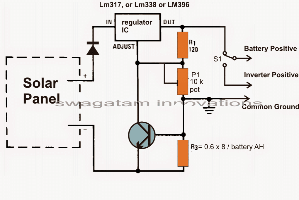
A simple solar panel voltage regulator circuit may be witnessed in the following diagram, the given switch may be used for selecting a battery charging option or directly driving the inverter through the panel.
In the above case, the regulator needs to produce around 7 to 10amps of current therefore an LM396 or LM196 must be used in the charger stage.
The above solar panel regulator may be configured with the following simple inverter circuit which will be quite adequate for powering the requested lamps through the connected solar panel or the battery.
Parts list for the above inverter circuit: R1, R2 = 100 ohm, 10 watt
R3, R4 = 15 ohm 10 watt
T1, T2 = TIP35 on heatsinks
The last line in the request suggests an LED version to be designed for replacing and upgrading the existing CFL fluorescent lamps. The same may be implemented by simply eliminating the battery and the inverter and integrating the LEDs with the solar regulator output, as shown below:
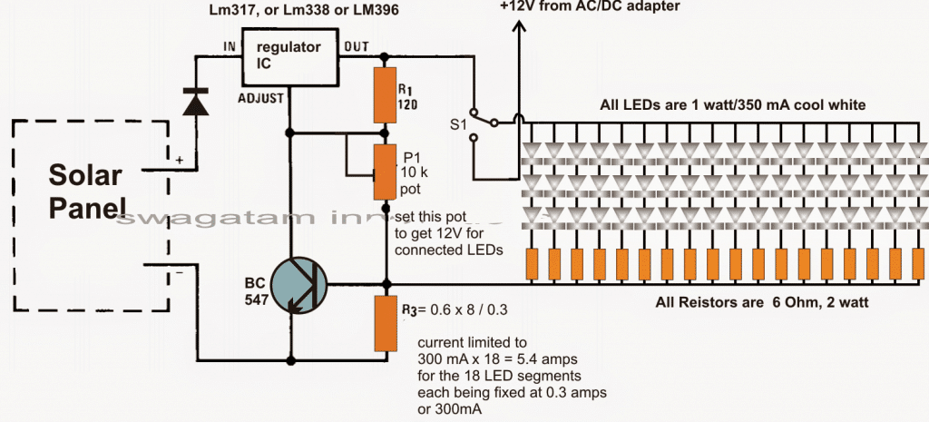
The negative of the adapter must be connected and made common with the negative of the solar panel
Final Thoughts
So friends these were 9 basic solar battery charger designs, which were hand picked from this website.
You will find many more such enhanced solar based designs in the blog for further reading. And yes, if you have any additional idea you may definitely submit it to me, I'll make sure to introduce it here for the reading pleasure of our viewers.
Feedback from one of the Avid Readers
Hi Swagatam,
I have come across your site and find your work very inspiring. I am currently working on a Science, Technology, Engineering and Math (STEM) program for year 4-5 students in Australia. The project focuses on increasing children’s curiosity about science and how it connects to real-world applications.
The program also introduces empathy in the engineering design process where young learners are introduced to a real project (context) and engages with their fellow school peers to solve a worldly problem. For the next three years, our focus is on introducing children to the science behind electricity and the real-world application of electrical engineering. An introduction to how engineers solve real-world problems for the greater good of society.
I am currently working on online content for the program, which will focus on young learners(Grade 4-6) learning the basics of electricity, in particular, renewable energy, i.e. solar in this instance. Through a self-directed learning program, children learn and explore about electricity and energy, as they are introduced to a real-world project, i.e. providing lighting to children sheltered in the refugee camps around the world. On completion of a five-week program, children are grouped in teams to construct solar lights, which are then sent to the disadvantaged children around the world.
As a not 4 profit educational foundation we are seeking your assistance to layout a simple circuit diagram, which could be used for the construction of a 1 watt solar light as practical activity in class. We have also procured 800 solar light kits from a manufacturer, which the children will assemble, however, we need someone to simplify the circuit diagram of these light kits, which will be used for simple lessons on electricity, circuits, and calculation of power, volts, current and conversion of solar energy to electrical energy.
I look forward to hearing from you and keep on with your inspiring work.
Solving the Request
I appreciate your interest and your sincerely efforts to enlighten the new generation regarding solar energy.
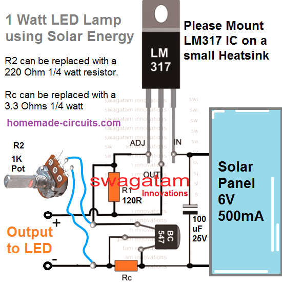
I have attached the most simple yet efficient LED driver circuit which can be used for illuminating a 1 watt LED from a solar panel safely with minimum parts.
Make sure to attach a heatsink on the LED, otherwise it may burn quickly due to overheating.
The circuit is voltage controlled and current controlled for ensuring optimum safety to the LED.
Let me know if you have any further doubts.
Request from one of the avid readers of this blog:
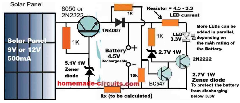
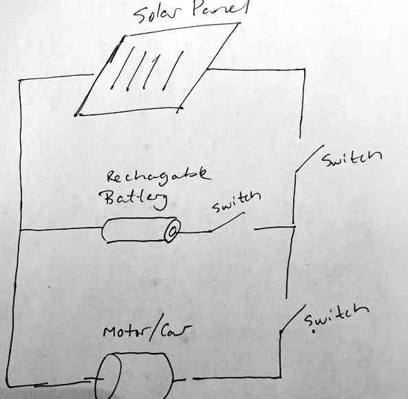
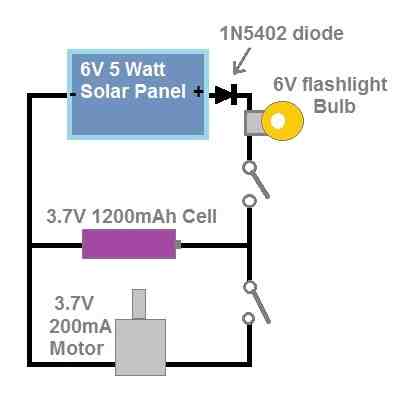
Hi, thank you for everything you do to help people out! My son would like to create a science fair experiment where he can show an electric car running on a solar panel only during the day while charging a battery and running on battery only during the night. For this, we planned to have a small solar panel connected to a battery and motor in parallel (see the attached drawing).
- Will this work?
- Can you recommend a size of solar panel, battery and motor?
- As to not overcharge the battery, should a resistor be added? What size would you recommend?
- Should a diode be added? What size would you recommend?
My Reply:
- yes, it will work.
- Use a 6 to 8V 1-amp solar panel.
- The switch in series with the battery is not required. The remaining two switches are fine. This switch can be replaced with a 4 ohm 2 watt, or simply a 6 V flashlight bulb.
- This bulb will illuminate while charging and will slowly shut off as the battery gets fully charged.
- You can add a diode in series with the positive wire of the solar panel. It can be a 1N5402 diode
- The battery can be any 3.7V 1200mAh Li-ion battery.
- Motor can be any 3.7V DC motor.
More Questions:
Couple more questions, I cannot find a solar panel with those specs, do you think you could send me one on the internet so I can find something similar? Great idea on the flashlight bulb, I assume this would need to be an incandescent light? Do you think this would properly protect the battery or would an additional resistor be needed?
My Reply:
For the solar panel, you can search for a 6V 5 watt solar panel.Yes, the flashlight bulb will need to be an incandescent type, so that the filament can be used to control the current.The bulb should be enough to control the current, no additional resistor will be required.Please find the attached diagram for the detailed schematic.

Questions & Answers
Good Evening Sir
On the last diagram of project 5, (the simplified transistorized) where can one feed in the charging and full charge indicator LEDs ?
Good Evening Ngang,
Unfortunately, battery status LEDs cannot be added in those designs directly….they can be added through an external opamp circuit or LM3915 based circuit, or separate BJT based low battery and full battery indicator circuits…
Good day Sir.
Can BD243 be used for the first transistor instead of 2N2222?
Hi Godwill, yes it will work, however it would like using an elephant in place of a horse to pull a carriage…not recommended
Hahaha
Good day Sir. l have removed the elephant and put the hors me and everything is working well.
I have utilized it to build emergency lamps Thank you Sir
Good Day Godwill,
Hahaha, you did the right thing, 2N2222 is the BJT and the work”horse” transistor for your specific application.
You are most welcome…
Hello sir, I am Gagana. I am pursuing my diploma final year in EEE. Now as a final year student we have to present a project so we have choosed the project title wireless solar powered EV charging station . We are facing problem in the circuit, we have no idea how to connect it , we searched in my websites though we didn’t get our circuit but we purchased some components like transmitter coil and reciever coil with its green board so sir please can u help us building a circuit or sir can u exactly tell what r the components we can purchase. And we are using 3 watt 9 volt solar panel for our project and rechargeable lithium ion batteries.
Hello Gagana,
I can give you the complete circuit diagram with all the details, just give me two days…
By the way I already have one such similar topic posted on this blog, you can check it here:
https://www.homemade-circuits.com/wireless-cellphone-charger-circuit/
I am gagana’s project teammate sir. As she requested please share the circuit diagram as you told sir please
Hi, you can find the details here:
https://www.homemade-circuits.com/make-this-ev-battery-charger-circuit/
Hi Karthik, I am designing the circuit now…and will give you by tomorrow morning, because I am designing a professional level design, not a hobby level…so it is taking little time.
Hello sir I am Karthik , thank u sir for that circuit but we have a problem about the circuit itself so we tried to contact u through Instagram but u didn’t reply. Actually the problem is we already bought a ready made transmitter and receiver coil which comes with a green board which directly converts ac to dc and dc to ac recommended by our seniors so sir please can u make us a circuit again and please reply us on Instagram so we will send our seniors model of that project and some pics of that model
Hello Karthik,
I am not active on Instagram, so I cannot reply you there, you can send me the pictures of your circuit boards on my email ID
homemadecircuits
@gmail.com
Swag, I’m looking to build a solar panel, charging (8) AA NiMH batteries that also has dusk to dawn that powers an LED (12v, 19 lumens). This will be mounted outdoors for a Halloween decoration for the month of October. The LED I have seen (Amazon) uses 8 AA batteries. As I live in Washington State we have about 8-9 hrs of daylight that time of year. I probably don’t need that many batteries but the LED drops off when the voltage drops to 9 volts. I’m new to all this and wish I paid more attention in my high school electronics class. I have done soldering of circuits before so I’m not completely new to all this. I also know how to waterproof everything.
I love this website and have spent lots of time going over alot of the material; simply amazing!
Hi Gary,
You can learn basic electronics from this website. Anytime if you want to learn anything new, just let me know.
Each AA cell = 1.2V, and your LED is 12V, so yes you will need 1.2 * 8 = 9.6V minimum to illuminate your 12V LED.
In fact you will need 10 of them in series.
However, since it looks like your LED current is very low, because its lumen capacity is just 19…so you can simply use a couple of AA cells in series and illuminate this LED with a buck converter in the middle.
Or you can simply use a Joule thief circuit, as explained in the following article. Let me know your opinion and I will quickly design the whole thing for you.
https://www.homemade-circuits.com/1-watt-led-driver-using-joule-thief/
hello again! another question regarding modifying circuit #4 to use a 18650 lithium battery:
my miniature solar panels put out 5V, not 6V. is that going to be a problem with the circuit as we’ve discussed with a 5V relay and 5.3V Zener?
Hi, unfortunately a 5V solar panel will not work for the specified application.
In that case you may try the first circuit explained in the following post:
https://www.homemade-circuits.com/simplest-automatic-led-solar-light/
Hello sir. My name is Emmanuel OKEDOKUN. I am one of your fans using one of your projects call the transistorized solar solar charger for a lithium battery of 12 volts 28 amps. I love the charger with all his future features and performance because I’m using it to charge one of my little lithium battery of 12 volts 23 amper. However I want to upgrade my solar system to a bigger one. please can you assist me to make a charge controller of transistorized type that can handle 50 amps of solar panel and charge and charge 200 amps of lithium battery. kindly equip it with overcharging protection. Thank you sir.
Thanks Emmanuel,
I think the following circuit will do the job for you. Over charge cut off may not be required if you adjust the max charging voltage output from the charger slightly lower than the extreme full charge level of the battery:
what if I connect two 5V panels in series will it work then? would be 10V 60mA supplied. they don’t make 6V miniature panels, at least I can’t find them.
Yes, that would work, but with a relay, the LEDs would turn ON too early, maybe at around 4 or 5 evening, that is why i would suggest you to go for the transistorized circuit which I gave in one of my earlier comments.
I’ll give it a try! if I use an 1800 mAh battery and a 30mA LED the early activation shouldn’t be a problem for the battery.
I Just forgot the charging current issue. A 60ma solar panel would take ages to charge a 1800mAh battery, it should be at least 300 to 500mA, which might allow the battery to get charged within 6 hours of peak sunlight. So it seems a 60mA solar panel might just not be enough.
Hello, good afternoon, Mr. Swagatam. I would like to ask if you have a circuit for charging 18650 lithium batteries without a transformer… That is, with a capacitive power supply. But it has to be a very safe charger because it has to be permanently connected and in my children’s room… Thank you very much in advance.
Hello Carlos,
A capacitive power supply can be made safe for charging 18650 lithium batteries, but it may not be safe for humans. If any section of the circuit connection is exposed and is touched while the circuit is powered ON, it can give a lethal electrical shock….so i won’t recommend it.
yes true but I don’t think 10-12hrs powering a single LED will drain the battery much? for the same reason I don’t think an overdischarge circuit is necessary. if I’m correct here the 60mA panel will replace most if not all of that loss.
I forgot the relay now needs to be rated 10V not 5…any other adjustments other than the LED resistor?
Sure, that makes sense! For the relay you can use 10V relay if it is available, or a 9V relay with a series 1N4007 diode just to drop that extra 1V, that’s all, no other changes would be required.
Also, since you have an extra 6V from the panel, you can consider replacing the transistor regulator with a buck converter to convert the excess voltage into extra current for the battery…. which means 60mA could well turn into 130mA.
did some reading…place the converter between the panel and the circuit and adjust the output to 6V. then I can use your original circuit, correct?
That’s correct! You have to do exactly that. Place the buck converter between the panel and the relay circuit, and let the buck converter transform the excess voltage from your solar panel into extra current for faster charging of your battery.
first of all apologies for the much delayed reply. I realized after I sent it the LED resistor never sees the charging side of the circuit. I’m intrigued by a buck converter boosting the charging amperage, but truthfully I’m clueless how to implement that. can you point me in the right direction?
Good morning Sir.
Can circuit 4 be used just for overcharging protection of 18650 lithium ion battery?
And how can I modify the circuit if the only available zener diode is 5.1V ?
H Godwill,
Yes you can definitely use this design to protect any battery from overcharging, simply by selecting the zener diode value such that the emitter output voltage from the transistor becomes slightly lower than the max full charge voltage value of the battery.
4) Automatic Solar Light Circuit using a Relay
this circuit’s exactly what I’ve been looking for! I’d like to modify (if possible) it to run off a single 3.7V 18650 Lithium ion cell. could you point me in the right direction? many thanks!
Thanks for your interest in this circuit.
For charging a 3.7V 18650 Lithium ion cell, you can do the following modifications:
Replace the relay with a 5V relay.
Adjust the zener diode, so that the voltage at the TIP122 emitter terminal reads precisely 4.1V. Make sure to connect a 1k resistor across the emitter of the transistor and the ground, otherwise the voltage reading will not be proper.
The solar panel can be a 6V or 9V 2 amp panel.
Wow….thanks for the quick reply! Digikey sells 4.1V Zener diodes, but one question:
I’d like to use three small solar panels in parralell with a total current of 120mA…will that work here? Charging time shouldn’t be an issue since the LED is the only load and won’t draw much from the battery…correct?
You are most welcome! The output from the emitter will be around 1.2V lower than the zener value, so maybe you may have to use a zener diode rated at 4.1 + 1.2 = 5.3V, or tweak the output level accurately using zener + 1N4148 diodes. 1N41418 diodes must be connected in reverse to the zener direction….all of them in series. Yep, 120 ma should be quite enough for any sort of LED….just make sure to connect a limiting resistor in series with it, using the formula: R = (emitter side voltage – LED fwd voltage)/LED max current
Good morning Sir,
Why do you say the output voltage at the emitter will be 1.2v lower than the zener’s village?
In the similar calculation on the last circuit of project No 5 above, you added but 0.6 to zener’s voltage to obtain full charge voltage of battery.
Good Evening Ngang,
If the BJT is not a Darlington, then the drop will be just 0.6V, however for a Darlington BJT like TIP122 which has two BJTs tied up internally, their 0.6 + 0.6V internal drop will give rise to a total of 1.2V.
Good morning Sir Wow, well understood Sir. Thank you so much. This information is also very useful
No problem Ngang, glad you found the information useful…
again thanks for the quick replies! one quickie: would it make sense to add another diode on the ground trace just to the left of the LED to protect the solar panel from positive voltage when the LED gets activated? I’m a newbie so maybe I’m way off here?
Sure, if you want to add a protection diode for the solar panel as well the circuit, then the best place is to put in series with the positive terminal of the solar panel, as shown in the following updated diagram:

But there’s a major drawback of this circuit, the LEDs might turn ON very early, maybe around 5 o clock evening, so I would rather recommend the following transistor version, which works in the same way as above but turns ON the LEDs only when it is quite dark…