A simple construction procedure of a motorcycle electronic 2 pin turn signal indicator with beeper circuit has been thoroughly I have explained in this article.
Normally, the electro-mechanical types of turn signal indicators are not reliable due to low consistency and vulnerability to changing weather conditions.
The present design easily withstands the above parameters and more importantly consists of an attached buzzer indication facility.
The inclusion of an audible signal makes it sure that once the required deviating turn is completed by the vehicle; the driver remembers to switch off the unit and save precious battery power
Conventionally a turn signal indicator will require three output terminals for its correct operation.
Uniquely the proposed circuit works with just a couple of terminals, and moreover incorporates a built-in buzzer.
Here we explain a simple motorcycle electronic turn signal with beeper circuit.
Video Test Result
Introduction
Also popularly known as “flasher with buzzer,” turn signal actuators are indispensable piece of devices for every vehicle.
The device is particularly used for switching or flashing the side indicator lights (left or right) of a vehicle while making a turn or a deviation from its normal path.
Basically the flashing of the lamps acts like a warning signal and makes it easier for the other vehicles to identify the track of the indicating vehicle.
This averts a possible collision and misunderstanding between vehicles. The device thus specifically helps in avoiding accidents and mishaps.
Nowadays many folks prefer the above devices accompanied with an audio indication like a buzzer or a beeper which may produce a rhythmic note with the light switching.
This facility proves to be useful in two ways, first: it assures the driver regarding the perfect working of the entire system and second: when the necessary deviating move or a turn is completed, the audio note keeps reminding the driver that the unit is still ON and needs to be switched off, thus saving precious battery power and false indications.
Cheapest 2-pin Flasher Buzzer for 2 Wheelers
The present circuit of a motorcycle electronic turn signal flasher with beeper has been exclusively designed by me and tested thoroughly, in fact I have already sold more than 90,000 pieces of them in the market and the demand keeps growing.
The circuit described here is very unique because of the following reasons:
· Its 2-pin design makes it compatible with almost all 2 wheeler wiring system.
· Since it is electronic and solid-state becomes very long lasting and weather proof.
· A built-in high quality piezo buzzer makes it a better choice with the folks.
Parts List
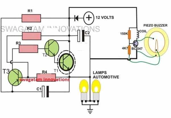
- R1, R2, R3 = 10K,R4 = 33K,T1 = D1351,
- T2 = BC547,
- T3 = BC557,
- C1, C2 = 33uF/25V
- D1 = 1n4007,
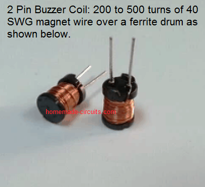
- COIL = Buzzer coil
Circuit Operation
Let’s try to understand its functioning with the following points:
From the circuit shown alongside we see that the whole circuit is built around just three inexpensive active components T1/T2 and T3.
A few other passive components in the form of resistors and capacitors are used to initiate the flashing action and sustain it as long as power remains switched ON to the circuit.
When power is first switched ON, capacitor C1 slowly charges via R1.
The moment it reaches its full charge, T3 is able to conduct and provides some sort of an initial biasing voltage to T1/T2.
T1/T2 partially conduct and in the process turns ON T3 much harder through R2, because now T3 receives full biasing through R2, T1 and the lamps switch ON.
The lamp now receives full power through T1/T2 and ignites.
But around this time C1 almost instantly discharges through R1, T1/T2 and the lamps, blocking the emitter of T3.
T3 immediately stops conducting, so does T1/T2 and the lamp shuts-off influencing a fresh cycle to begin. The lamps thus start flashing.
D1 and C2 are placed to filter out any AC component or spike that may be present in the auto electrical while it’s in motion.
The circuit of this motorcycle electronic turn signal beeper also incorporates a small yet powerful buzzer circuit connected in parallel to the supply line.
During the flashing process, at the instants when the lamp is turned ON the buzzer stops sounding and vice versa.
This happens because the lamps suck out almost all the power from the circuit and the buzzer is not able to receive the required voltage and is able to beep only when the lamp shuts off in between.
2-pin Turn Signal Flasher using a Single IC 4093
A single gate of the Schmitt Nand IC 4093 works like a 1Hz free-running-multivibrator and the remaining three gates in parallel function like a buffer stage to turn the BUZ1 1 power mosfet ON/OFF.
Zener diode shields the entire flasher circuit from voltage transients.
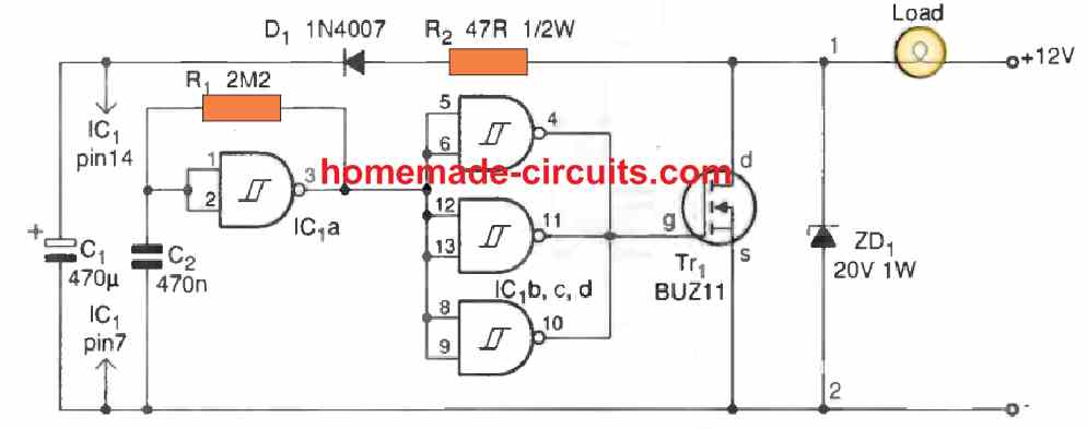
At power switch on, the status of the gates are such that the mosfet remains switched off and C1 starts charging through D1, R2 and the automotive lamp.
Throughout this period, C2 gets charged via R1, finally turning ON the multivibrator, and switching the mosfet and the series lamp ON.
The Power to the 2 pin flasher circuit is delivered throughout this time period is through the charged C1.
Capacitor C2 now begins discharging by means of R1; the opposite course of action starts transpiring, the mosfet is now turned off, making it possible for C1 to begin charging up again so that the cycle keeps repeating.


Questions & Answers
Hi Swagtam, I need two pin led flasher for my bike in which i replace the conventional lamp to led . But the built-in flasher does not run the led to be flash. It has two pin. So i want a two pin flasher circuit so that i can fit it in the flasher unit. Pls help mw out
Hi Chandrashekhar, you can try the first concept from the above article. Everything can remain as is, except T1 which can be replaced with TIP122. Also, make sure the LED is rated at least at 1 watt.
Hi swagtam it works, but the led not completely off and it glow little in off stage. With that the buzzer not running smoothly. However with lamp it run fine… But with LED It not completely off in off stage..pls suggest
Hi Chandrasekhar,
LEDs can remain illuminated even at upto 2V therefore it may show some glow even while the flasher is at the lowest shut off point. You can try adding a couple of 1N4007 diodes in series with the LED module and check if that helps or not. Regarding the buzzer I am not sure what may be the issue? It will need to be diagnosed practically.
thank you. It works
Glad to know it worked, thanks for updating!
But now the buzzer connected with the flasher two pin output dont beep. How to connect it for beeping for aby turn sognal when it is on.
Buzzer should beep when connected across the 2 output pins of the circuit. Remove the LEDs and connect a normal incandescent bulb and check if the buzzer beeps or not….if not then your buzzer may be faulty.
Ok now new buzzer is beeping. The problem is the led is not complete turn off while flashing, it dim little bit. How to get rid of this pls?
Then unfortunately there’s no remedy for this problem, because the circuit needs a high current load for functioning effectively.
Your design have less component then the diagram you gave in the post. Please explain your design of video you made.. I see that u have 2 capacitors 2 resistors and 2 transistor only..
Please add the details of video design…
The diagram in the above article has a buzzer section, barring that rest everything is same as in the video. Also in pace of T1, T2 you can use a single TIP122
Thank you very much
Thanks for your reply sir.. Is there any same other circuit that you make that works with LED bulb?
Can you please provide me a link sir..
Thanks a lot..
Paul
Hi Paul,
you can try one of the concepts explained in the following article
https://www.homemade-circuits.com/how-to-make-any-light-strobe-light/
Hello,
I have constructed this circuit and it was beeping and flashing but my problem is that the LED is not completely turn off when flashing.. How can i make it turn off completely when flashing
Thanks
Paul
Paul, the shown circuit is designed to work with filament lamps only, it will not work properly with LEDs s far as I know.
Hi sir
I connected this ckt with activate Honda
I observed that after some time d1351 becomes too much hote and it burned out
Why?
But same ckt is working well with others bike.
Hi LR,
Honda Activa has huge indicator bulbs almost twice the size of the other motor bikes…therefore you may need a bigger transistor to handle the huge current supply for the bulbs.
moreover D1351 was chosen to cut down cost since I had to sell the unit at very low prices in the market during my manufacturing days.
to solve the issue, you can replace T1/T2 with a single TIP142 transistor…but still make sure to connect a small heatsink with this transistor also.
Hi, are the resistors are half watt or quarter watts
all are 1/4 watt
I want to replace my stock flasher with a one which can flash LED Bulbs. Do you have a circuit that can do it or can this circuit be used with some modifications. I need a load independent circuit so the led wattage can vary.
Thanks.
the above circuit is load dependent, you can try the first circuit from the following article:
https://www.homemade-circuits.com/2011/12/make-interesting-flasher-and-fader-led.html
replace the LED/1k with a relay coil, then you can use the relay contacts for flashing the LEDs in series with the supply voltage.
use a diode in parallel with the relay coil
how to make it glow alternatively also is it possible to adjust the speed..please do a circuit such that it will blink fast 2 or 3 times and after 5 sec again blinks like that 🙂
I have corrected the above explanation, please refer to it,
Thanks for indicating the issue.