You might have probably come across these fantastic high power, high efficiency LED modules and wondered how do you make these? Here I have explained how to make a 100 watt LED flashlight out of it?
Introduction
The article revises the datasheet of this LED module and explains a simple driver circuit which can be used for operating it safely for the intended lighting purpose.
So far we have learned about LEDs with rather smaller features and applications. However the present article finds out how a LED module in the order of 100 watts can be actually used for illuminating a house at costs probably 5 times lower than the conventional lighting devices.
100 Watt LED Module Image
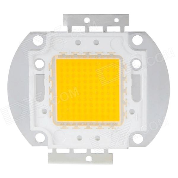
We have all studied a great deal about LEDs and about their high-efficiency with power consumption.
The LED technology has helped us to design and incorporate very high intensity light installations at minimal consumptions as compared to the other conventional form of lighting concepts.
Lower power consumption also means low heat emissions, which again is an added feature and helps to keep the crucial issue of global warming at bay when LEDs are utilized.
As days pass by, technology keeps on improving and we are able to witness many incredible and unbelievable results with these outstanding lighting devices.
The 100 watt LED module is one such marvel of modern science which has created a breakthrough in the field of LED lighting.
Not surprisingly, the device is able to generate an astonishing 6500 lumens of light intensity at a consumption of mere 100 watts, but the interesting part is the size, which is barely 40 square mm.
The saving made by these devices is estimated to be five times more than any other form of light producing device and the if we compare the specified intensity of 6500 lumens, that corresponds to an excess of 500 watts light power that might be acquired from a halogen lamp.
Let’s discuss the important specifications of this amazing LED in brief and in such a way that even a layman understands:
100 Watt LED Datasheet
Typically the preferred color is white, as that produces the most favorable and desirable illumination for all applications.
- The power consumed is 100 watts for optimal performance.
- The emanated heat for the specified white color is up to 6000 Kelvin.
- The intensity of light generated with the above specs is a staggering 6500 lumens.
- Typical operating voltage of the device is around 35 volts.
- The current required for producing the above light intensity is around 3 Amps.
- ESD level is safe and very high up to 4000 V.
- The safe operating temperature level is very wide, ranging from minus 40 to 110 degrees Celsius.
- The optimum angle of viewing is also wide, up to 120 degree.
- Dimension of the unit is truely mini, the height being 4.3 mm, length 56 mm and width 40 mm only.
Typical Specifications
- LED Type: 100W COB LED
- CRI: Ra70-80/ Ra80-85/ Ra90-95 / Ra95-98
- IF (Forward Current): 3500mA
- VF (Forward Voltage): 29-34volts
- Chip Category: Bridgelux
- Power Output: 100 Watt
- Angle of Beam: 120 degree
- Illumination Magnitude: 10000-14000lm
- Substrate: high-grade copper
- CCT: 3000K, 4000K, 5000K, 6000K.(any CCT can be customized)
- Main application areas: Spotlight, Roving head light, light in stage shows, photography, High intensity rescue floodlight, etc
The specification narrated are sufficient for illuminating a 20 square meter space amply, almost at flood light levels ….. baffling.
Main Features of the 100 Watt LED
The advantages include the following:
High power light output without degradation even after long usages.
Highly robust mechanical specifications, involving less wear and tear and high resistance to changing atmospheric hostilities.
The overall performance is consistently optimal throughout the operating life.
Having discussed the above features of the proposed 100 watt LED lamp, it would be interesting to also learn regarding a useful recommended circuit that may be used for driving or operating the device at safe levels.
How to Make a Current Controlled 100 watt LED flood Light Circuit
A simple two transistor, powerful current limiter, LED driver circuit, which can be used for converting the above discussed device into a 100 watt LED flashlight or to be more accurate, a floodlight is described below:
The circuit of a 100 watt LED flood light shown below has been discussed in few of my other articles also, due its versatile and rather straightforward design; the circuit becomes very suitable in places where current limiting at low costs becomes an issue.
Though the discussed designs mostly dealt with low current applications, the present circuit is specifically intended for handling high currents and up to 100 watts and more power.
Circuit Diagram
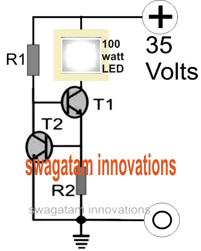
Looking at the figure we can see a couple of transistors are coupled together such that the base of the upper transistor T1 becomes the collector load of the bottom transistor T2.
The upper transistor T1 which actually carries the LED current is quite vulnerable itself, and is not equipped to control the amount of current through itself and the LED.
However since the base current of this transistor decides the amount of collector current that can pass, it simply means that by restricting its base current to some safe specified levels, it might be possible to keep the overall consumption within tolerable limits.
A current sensing resistor connected at the emitter of T1 is used to convert the current consumed, into a potential difference, across it. This potential difference becomes the base trigger for R2.
However as long as this voltage is below 0.6 volts or simply below the minimum forward voltage drop of T2, T2 remains unresponsive, but once it starts exceeding this value, triggers T2 which in turn clamps the base voltage of T1, rendering it inactive.
This instantaneous cut off of the base drive to T1 shuts the LED for some fraction of a second, bringing the current and the potential drop across the current limiting resistor to zero.
This action reverts the circuit to its original stance and the LED is again switched ON.
The process repeats a number of times per second to keep the LED and the current to safe and precisely tolerable limits.
The value of R2 is calculated in such a way that it keeps the potential difference across itself below 0.6 volts until the LED current reaches 100 watts, after which the restricting process begins.
Warning: The LED must be mounted on a correctly optimized heatsink as per the specifications provided in its datasheet..
How to Calculate the Constant Current Limiting Resistor
For calculating R1 you may use the following formula:
R1 = (Us - 0.7)Hfe/Load Current,
where Us = supply voltage, Hfe = T1 forward current gain, Load current = LED current = 100/35 = 2.5 amps
R1 = (35 - 0.7)30/2.5= 410 Ohms,
wattage for the above resistor would be = 35 x (35/410) = 2.98 or 3 watts
Formula for calculating R2 is:
R2 = 0.7/LED current
R2 = 0.7/2.5 = 0.3 ohms,
wattage may be calculated as = 0.7 x 2.5 = 2 watts
For an SMPS driver circuit please refer to this article
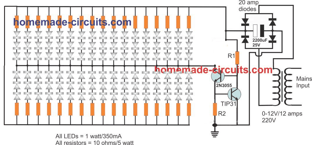
Current Controlled 100 watt LED Lamp complete schematic




Questions & Answers
I mean in what diameter 100 wt led flood light could be available?
You will have to check the datasheet of the lamp to find the exact diameter.
What are the component values to power 3 Lamps using 100 W, and 2 x 50 W lamps?
(i. e. Double the Wattage of the Circuit shown.)
What will be voltage rating of the LED modules?
one question please so this One cob led of 100 watt is consuming around 30-35 volt and 2.8-3.2 amper per hour right? i am wrong in something. also the minimum specs so this led cob can light on what are? thank you in advance
Your calculations are correct! The minimum specs can be 24V 1 amp, but this is as per my assumptions, I have not verified it practically
ok so i have a panel that can totaly light on 4 of that 100 watt led in a serie it means for sure the 3 of them is in full consumption right? and maybe the other one could be lower is is true to give to 4 of them full light means minimum lights on full the 3 of that i am correct thank you
You have not mentioned your panel specifications? And I can’t understand what exactly you are trying to ask!
trying to understand the panel power it can light on 5-6 100 watts in a row we know the volts around 100 can we find somehow amperes?
we know only volts and can light up strongly 5 leds of 100 watt without any problem for hours for that i am asking how to find the watts or amperes to know an estimated
Please use Ohm’s law for the calculations!
You can use Ohms law for the calculations: Current(I) = Watt (W) / Volts(V) = 100 / 100 = 1 amp
I am actually a B Tech civil engineer, but very much interested in electronic circuits. I assemble small and simple circuits and most of them work, some will not work. I don’t know to trouble shoot the reason for not working the assembled circuits because I am not an electronic engineer and know very less about the theory of working electronic components.
You will have to learn all the aspects from the beginning, and gradually grasp the theories along with practical experimentation…..this can take a lot of time…
Thanks for your response/reply.
I am actually trying to eliminate the driver(ac input) that comes with a 30w/50w led flood light unit and instead power the led flood light module with solar panel output as there is no mains supply in my location.
Guide me to realising this Sir.
I have two solar panels of 120 watts/12V.
Thank you Sir.
Oga, Please build the circuit which I provided in the link, your problem will be solved
hi in need your help in digital TDS meter reading is not stable
Sir how do I get 35V from a 12V battery to drive a 50w ac flood light above? Thanks.
Oga, you can try the following circuit
https://www.homemade-circuits.com/high-power-dc-to-dc-converter-circuit-12-v-to-30-v-variable/
Thanks Sir,Sir Is the aluminum plate is the heat sink used in this. Circuit?
yes heatsinks are always made with aluminum, make sure that the aluminum plate is much bigger than the area of the LED measured…you can bend the extra length of the aluminum backwards at 90 degrees to make the design compact
Thanks Sir,But sir my query is where I can connect heat sink in this given circuit? and what is the specification of heat sink? Plz sir help me.
Ritesh, I have already explained elaborately in the previews comment, please check the previous replies…
Sir where I can use the heat sink in this circuit? What is the specification of heat sink?
use heatsinks for the LEDs and the transistors
Thanks Sir,Sir how I can get 35 volt from 12volt transformer ?
as per the shown diagram you will need only 12V, 10 amps for the operating the 102 LEDs
Thanks Sir, Sir where I should use the heat sink,?And what is the specification of good heat sink,,,?
first find out how much total area the 102 LEDs would consume. next buy an aluminum sheet, 2mm thick with area as per the LED distribution measurement.
after that mark straight lines on the aluminum and determine the exact spots where the LeDs needs to be stuck on these line
as per the diagram layout start sticking the flat base of the 1 watt LeDs tightly with fevibond, use only fevibond no other adhesive.
make sure that the polarity are perfectly correct.
keep for drying, once hard and dry…start wiring the LED ends as per the diagram…and finally finish the remaining connections also as per the schematic.
test the module with the supply, if all the LEDs light up successfully you can assume that the LED were correctly fixed with no polarity errors, if not then check those specific series connections for the fault.
once everything is fixed, reinforce the LEDs on the aluminum with transparent epoxy glue such as Araldite….keep for drying until hard.
Thanks Sir, Sir how I can get 35 volt through a 12 v transformer Power Supply.? And how much led I can use for 100watt led? Is it 102 leds ?
Hi Ritesh, you wanted to use 1 watt LEDs, right? Therefore the shown circuit is designed using many series parallel 1 watt LEDs for creating a 100 watt LED module.
yes 102 LEDs will be required and will need to be connected as shown in the diagram.
Make sure to use a good heatsinking with the whole module.
Sir!
Thankyou so much for your quick respond.
But I want to vary the brightness of 100 watt led ( 100 noes of 1 watt leds)by useing a variable resistance for R2.How can I solve this problem with the new concept that you suggest me?Or for the sake of varying brightness,I have to stick with this circuit and combine it with the circuit of your suggestion?
Shigida, you can use the the first design from the following article:
https://www.homemade-circuits.com/how-to-make-current-controlled-12-volt/
Make sure to replace LM317 with LM338, fix Rc value as per the calculations.
And then you can use the voltage control pot for varying the brightness.
use a 22k pot for R2, and use a 24V as the input.
connect the LEDs as explained in the previously linked artilce.
Sir!
instead of a single 100 watt Led,i want to use 100 noes of 1 watt Leds by configuring them in series and parallel appropriately.Is it necessary to calculate and connect a resistor for each of
series line?I think by doing that,i can get a light even iff one of the series line going to burn out.
Isn`t it? Or you mean in this case ,there is no need of this circuit at all.I am confused.help me pls.
Shigida, a current controller will be required for all high LED circuits, for your application you can try the following concept and apply it as per the available voltage specification
https://www.homemade-circuits.com/make-this-1000-watt-led-flood-light/
Thanks. Can we use mpp type of capacitor like used in induction motor? These are easily available and cheap too.
you can use any type, it just needs to be a non-polar and rated at 400V
Hi swagatam, is it possible to drive a 100 watt led directly from 220 volt using capacitor based power? As for volt is 32 volt can we put more nos of such 100 watt led to match ouput of capacitor volt. Can capacitor based power supply handle 3 amp of current?
Hi Webmaster, yes a capacitive power supply can be built for driving a 100 watt LED using the technique that's explained in the following article:
https://www.homemade-circuits.com/2016/07/scr-shunt-for-protecting-capacitive-led.html
Hi, Swagatam,
I happened to come across your circuit and write up as i was trying to find some information for a diy project I am trying. I have a 50 w led chip light. Can I use a 12v 1a ad-dc adaptor to power it? what is the best way to power up the chip light for continous use? Any assistance would be much appreciated.
Hi Latif, 12V 1 amp cannot be used for driving a 50 watt LED optimally, because 12 x 1 = 12 watts, whereas your LED requires 50 watts.
so please identify the V and I specs of your LED and supply the specified amount power to it, without forgetting a current controller stage in the middle.
But where is the circuit diagram
for the input power you can use either a 35V transformer based power supply or an smps as described below
https://www.homemade-circuits.com/2014/09/32-v-3-amp-smps-led-driver-circuit.html
please suggest me to reduce the brightness of the LED
Dear sir,
I had 50W LED but getting much illumination than required so i want to know how to reduce the 50W illumination Please suggest me.
Santhosh, did you calculate the limiting resistor value correctly as suggested in the above article??
If it's calculated correctly then the LED will safely consumed the required amount of current.
If you provide the voltage and the current specs of your LED I might try to calculate it for you…
hey i want to make a circuit of 12V 8A AC/DC to run my project. Also I want it to be as compact as is can one like MVAB120 which is just 2" wide and 4" in lenght. Is it possible to make one my own. ur help is required.
sorry I do not have a 12V 8A SMPS circuit at the moment….