The stability of good quality RC oscillators can be expected to be around 0.1%, while normally we can assume the stability of LC oscillators to be up to 0.01%. When a much higher level of stability is required, we have to use a crystal based oscillator circuit.
The main reason why crystals are so important in oscillator circuits compared to LC networks, is their high degree of stability, which ensure precise oscillation frequencies with virtually no high output amplitudes.
LC resonance vs Crystal Resonance
As opposed to the electro-magnetic resonance associated with an LC circuit, we find an electro-mechanical resonance from the piezo-electric crystal. The only difference is that crystals could simply be processed through machines to get high precision results in terms of natural frequencies as close as 10 parts per million (ppm).
Which Material is used in Crystals
A number of crystalline materials, of which quartz happens to be a main example, have got the characteristics through which these are able to generate an electric field when exposed to mechanical stress. On the other hand, a quartze material tend to get physically deformed as soon as these are exposed to an electric field. This phenomenon is called the piezo-electric effect. As a result, you are able to cut a crystal to make it physically oscillate at some specified frequency as soon as it is exposed to an AC electric field.
Despite the fact that quartz is one of the most frequently used substances, other materials for example, lithium-tantalate, bismuth-germanium oxide, lithiumniobate, and aluminium-phosphate are also applied in several applications.
Additionally, you will find ceramic elements like the PZT ceramics being used for making crystals, which involves solid solutions of lead, zirconium and titanium. Yet another piezo-electric category includes polymers like polyvinyl chloride and difluorpolyethylene. For these materials, the piezo-electric characteristics is determined by how these are processed.
A fine plastic film using the above material is first warmed and then subjected to a powerful electrical field, and subsequently cooled down at room temperature. This process helps in the polarization of the substance, which subsequently gets the piezo-electric attributes.
Crystal Electronic Modelling
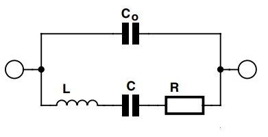
Looking with an electronic perspective, an RLC circuit as shown below could be implemented as a model for simulating the working of the crystal.

The inductor L can be compared to the mass of the quartz piece. The capacitor C compares to the the rigidity of the quartz piece. The resistor R corresponds to the energy losses taking place due to the physical distortions happening in the crystal.
The other capacitor, Co, behaves like the capacitance between the conductive electrodes coated on the two sides of the quartz material.
Normally, L can be a extremely large inductance while C is extremely low in value. For instance, in a crystal which is appropriately cut for vibrating at 200 kHz, L can be 27 H, C can be basically 0.024 pF, R can be 2 kΩ and C0 can be 9 pF.
The magnitudes like these are generally used while modelling the crystal behavior in computer simulations. The L to C ratio utilized is extremely high which we're able to obtain by making use of genuine electronic parts, providing the crystal an extremely high Q (quality factor).
A crystal often have a Q factor of around 100,000, whereas the Q of a most LC network is only in the range of a few hundred.
Operating Crystals in Series and Parallel Resonance Modes
You can operate crystals in the series resonance mode or in parallel resonance mode. When applied in the series resonance mode, the crystal behaves like a capacitor and inductance connected in series. The crystal impedance can be minimal (corresponding to R only).
When utilized in the parallel resonance mode, which can be somewhat larger, the crystal works like an inductor and capacitor hooked up in parallel. In this mode the crystal's impedance increases to the highest level at the applied resonance frequency.
Crystals are often cut in a way that allows them to operate optimally in either series or the parallel resonance modes.
The cut of the crystal determines how the crystal would oscillate, the manner in which it will vibrate, and the size of the crystal film that will be required for the implementation. In case, the crystal is excited for a longitudinal vibration function, the resonant frequency can be roughly calculated using the following given formula.
fo = 2.7 x 10³ / L
Here L denotes the size parameter of the crystal, where the unit will be in meter. The numerical constant in the formula symbolizes the phase velocity of the crystal's vibration.
Therefore, if the required frequency fo is selected to be 100 kHz, then L must be 2.7cm. In case fo is required to be 10 MHz, L would be 0.27 mm
Crystal Fundamental and Overtone Frequencies
Furthermore, they are often cut in a way that allows them to operate in the fundamental mode or at their harmonic (overtone) modes.
The overtones are the odd harmonics of the fundamental frequency of the crystal, that makes sure that the crystal is able to operate at the fundamental as well at its harmonics. For example if we have a crystal cut to oscillate at 100 kHz, then it should also oscillate at 300 kHz, 500 kHz, 700 kHz and at other bigger harmonics.
Crystal Limitation
One of the shortcomings that we may find in crystals is that when a crystal is cut to include a large fundamental frequency, may end up being extremely thin in thickness. Due to this it can easily become vulnerable to physical damage and breakage.
The highest frequency limit for fundamental mode crystals is approximately 70 Hz. Crystals made for operating at frequencies which may be in the range of many hundred MHz are cut such that they get a somewhat lower fundamental range but can be controlled in harmonic mode.
Through this method it is possible to get a maximum oscillating frequency of around 500 MHz for the crystal.
Thermal Stability in Crystals
Thermal stability is vital in certain oscillator applications. The temperature coefficient is determined by how a crystal is cut. As an example, the popular AT-cut provide crystals with a temperature coefficient of around ±0.002% for a temperature range of −55°C to +105°C.
This temperature coefficient range is equivalent to some % of most capacitors.
For getting an increased stability the crystal are often treated in an ‘oven’. In this process the crystal is cut so that it is able to acquire a minimum temperature coefficient at a temperature which may be higher than room temperature. Here, the oven is maintained at this specified higher than room temperature.
You may find disadvantages in this process due to the involvement of high power used in the oven, the involvement of huge bulky oven, and the amount of time taken by the oven to get heated.
However, the highly improved result that we get is an enhanced thermal stability for the crystal, approximately ±5 parts per ten million.
As high frequency communication channels increase, and as the clock speeds in digital circuits increase, crystals are gradually getting replaced by ceramic resonators. These ceramic resonators are usually tiny discs of PZT ceramics or similar piezo-electric components which are efficient at working with frequencies in the Gigahertz range.
Crystals in Oscillators
Due to their high stability crystals are employed to substitute or to partially substitute the LC resonant circuit stage in most oscillator circuits.
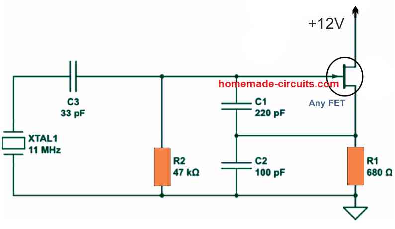
As an example, the crystal-controlled model of the Colpitts oscillator includes a crystal and a capacitor as opposed to the inductor L1.

When a crystal is installed in place of an inductor, the frequency gets a lot more accurately set. In this type of oscillator circuit, the crystals are generally controlled in parallel resonance mode, possessing highest possible impedance in the resonant frequency and thus generating an output frequency with very high amplitude.
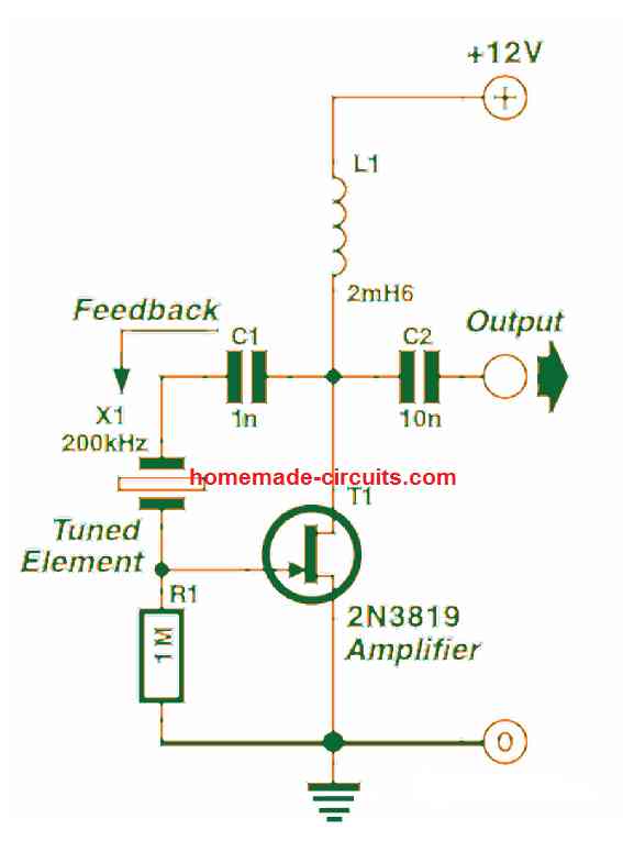
The Pierce oscillator demonstrated in the following figure is an example which exhibits a crystal working in the series resonance mode. Feedback is directed by means of the crystal and it attains the maximum level as the crystal resonates in the series mode, using minimum impedance.

Observe that this oscillator can work reliably with the need of a tuned circuit, depending simply on the crystal to decide its oscillating frequency. Crystal oscillators are not only very accurate with their functioning, they are in addition one of the fastest of the oscillators, typically. Present day digital circuits demand extremely fast clocks to operate them, with frequencies that may range in hundreds of megahertz.
Surface Acoustic Wave Devices
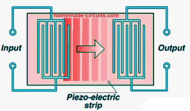
You will find a few of the fastest oscillators that work with surface acoustic wave (SAW) devices. They are tiny strips of piezo-electric substance having many electrodes plated towards their ends as shown below.
At one end which can be the input end, when an electrical field is applied between the electrodes, it results in the exterior of the strip to get deformed. This action produces an vibrational wave which travels along the surface area of the strip. This behaves like an acoustic wave which is able to move across the strip with very high speeds, as fast as the speed of the sound which is roughly 3000 m/s. After a fraction of a second, as soon as the wave influx extends to the other end, which can be the output of the strip, the electrical field involved with the wave generates a potential difference across the linked electrodes.

Since the gaps between the electrodes on the two ends ascertains which frequency would be fed more strongly into the SAW and retrieved from the other end, SAWs are generally applied in bandpass filters. The time required for the wave to travel across the strip provides the filter the characteristics of a delay line unit.
When used as an element of an oscillator, a SAW delay line can be used exactly in the above manner at the RC network of a phase shift filter. The time taken to create a phase shift of 180° is incredibly brief, and therefore, the frequency of this kind of oscillators is tremendously high. Normally, they range up to around 2 GHz. Oscillators that work with dielectric resonators in the feedback loop can even go beyond the 2 GHz range. At this level we could be effectively into the microwave spectrum, which possess their own specialized characteristics.
Post your comments here and get guaranteed replies. Comments must be related to the above article.