In this post I have explained the construction of a DC UV germicidal lamp ballast circuit which can be used for driving any standard 20 watt UV lamp through a 12 V DC source.
Although, the proposed ballast design was originally meant for illuminating a regular 20 watt fluorescent tube light, this can be also used for operating a 20 watt UV lamp, for the intended germicidal effects.
The following image shows the main features and image of a compatible 20 watt UV lamp.
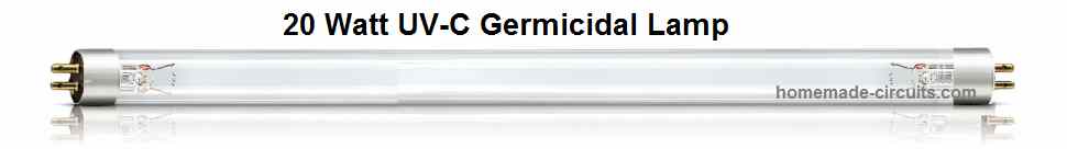
Lamp Features
- Short-wave UV radiation having a peak wave-length of 253.7 nm (UVC) effective for disinfection purposes against all types of bacteria and viruses.
- Specially created glass material of the lamp filters out the harmful 185 nm ozone building rays
- Inside protective covering guarantees practically constant UV output throughout the entire life span of the UV lamp.
- A Warning sign printed on the tube signifies that the lamp is designed to generate UVC.
Main Applications
- Deactivation of bacteria, viruses as well as other forms of microbes
- Domestic drinking water purification units.
- For purifying Fish aquarium water units.
- Disinfection of In-duct air treatment equipment.
- As Standalone air purifier systems.
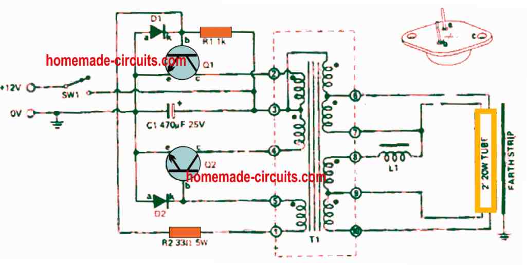
How the Circuit Works
Transformer T1 along with the transistors Q1 and Q2 work like a self-oscillating inverter stage. The operating frequency of the circuit is determined by the core material, the amount of primary winding and the supply voltage.
As described, the inverter is wired to oscillate at around 2kHz frequency when the input supply is provided from a 12.5 V source.
Parts List
| Quantity | Component | Description |
|---|---|---|
| 1 | R1 | Resistor 1k, ½ watt, 5% |
| 1 | R2 | Resistor 33 ohms, 5 watt, 5% |
| 1 | C1 | Capacitor, 470 µF, 25V, electrolytic |
| 1 | Q1 | Transistor 2N3055 |
| 1 | Q2 | Transistor 2N3055 |
| 1 | D1 | Diode, EM401, 1N4005, or similar |
| 1 | D2 | Diode, EM401, 1N4005, or similar |
| 1 | T1 | Transformer, see Table I |
| 1 | L1 | Choke, see Table II |
The secondary side winding of the transformer includes a couple of 4V windings to preheat the tube filaments, and also a 80 V winding to provide the discharge current supply across the tube and a 240V winding to generate a initial static voltage for starting the tube conduction.
Choke L1 can be seen connected in series with the 80 V winding of the transformer, in order to control the current through the tube.
Besides providing the current limit for the tube, the choke L1 also provides stabilization of the tube current for the supply voltage fluctuations.
When the input supply voltage rises, the inverter frequency also increases proportionately forcing the choke impedance to rise and vice-versa.
This automatically adjusting L1 impedance helps to keep lamp current steady in response to the variations in supply voltage between 10 V and 15 volts.
Construction Hints
The circuit schematic of the full UV lamp driver ballast circuit can be witnessed above. The winding info of transformer T1 and choke L1 are presented in Tables 1 and 2.
The winding for the transformer T1 is implemented over a 12mm x 12mm former or bobbin. The precise winding is easy to understand, yet somewhat laborious. The entire winding has to be done very uniformly; or else the whole winding may not accommodate well over the former.
Both the primary windings must be wound in a bifilar manner as explained in the following image.

This means that you must hold the wires for both the winding together and then begin winding the primary 1 and primary 2 simultaneously to make sure they are laid together in a combined way. This also implies that both these winding are laid down in perfectly adjacent with each other all through the length of the winding.
The other windings for T1 can be implemented in the regular fashion, but you must make sure that each of these winding is wound in the identical direction and also their start points and finish points are soldered to the appropriate terminals, as suggested in Table 1 below.
Table#1
| Winding | Start | Finish | Turns | Diameter | Notes |
|---|---|---|---|---|---|
| Primary 1 | Pin 2 | Pin 3 | 28 | 0.8 mm | Bifilar wound |
| Primary 2 | Pin 3 | Pin 4 | 28 | 0.8 mm | Bifilar wound |
| Feedback | Pin 5 | Pin 1 | 20 | 0.4 mm | 0.005" insulation |
| Secondary | Pin 8 | Pin 9 | 200 | 0.4 mm | |
| Filament 1 | Pin 9 | Pin 10 | 10 | 0.4 mm | |
| Filament 2 | Pin 6 | Pin 7 | 10 | 0.4 mm | 0.005" insulation |
| Starting Winding | Pin 3 | Pin 6 | 600 | 0.125 mm | 0.005" insulation |
After finishing the winding process, you may insert the pair of 'E' cores into the bobbin slots, and secure the whole construction firmly together using sticky tape or an appropriate metal clamp being careful that the metal clamp doesn't cause a short circuiting across any of the turn.
How to Wind the Choke
The choke L1 winding specifics are listed in Table#2 below:
Table#2
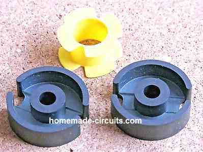
- Core: As shown in the following image or any similar contemporary pot core:
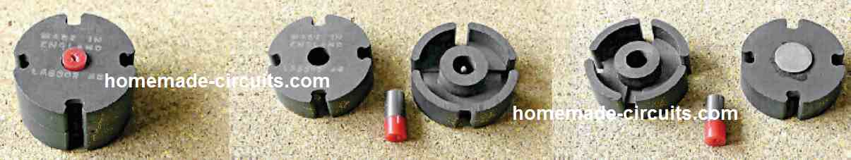
- Coil former: as shown in the image (in yellow):
- Note: cores should be clamped with each other through 3/16" brass bolt and nut- a 3/16" brass washer can be accustomed to create an air gap.
- Winding: 250 turns of 0.4 mm thick wire.
After the above steps, the winding are clamped between a pair of Mullard FX2242 cores as shown in the table#2 images. It is important to introduce a thin brass washer is interposed between the two cores, in order to create an air gap.
Wiring Layout
Wiring details of the parts and other aspects of the UV ballast circuit are demonstrated in the following figure. However, this exact component layout is actually not critical.
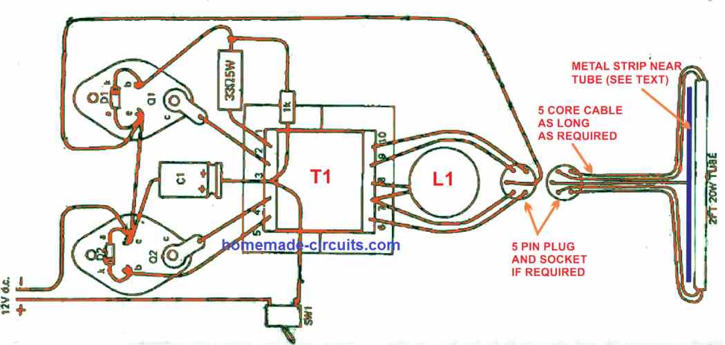
The transistors Q1 and 02 needs to be installed over an appropriate heatsink, which must have a minimum dimension of around 4" by 6".
Insulation washers should be applied to keep both the transistors well isolated from the heat sink. All the parts now can be casually hooked up and the full system attached to a 12V source.
Be careful not to touch the transistors or the transformer output side terminals because all these elements will be at fairly large voltage which could give you a painful electrical shock.
Current Adjustment
With the UV tubeligt switched ON, measure the current consumed by the circuit through the 12V supply. You should find this to be around 2.5 amps ± 0.2 amp.
In case you see this beyond this spec, you can try varying the air gap air of the choke until the issue is fixed to the specified limit. You will find that extending the the gap causes an increase in the current consumption and vice-versa.
Once the working and setting up are confirmed and tested, remove the transformer and immerse it into varnish in order to coat it with a layer of insulation, and let the varnish solidify across the winding and core. Once the transformer is entirely dried up, reconnect all the components for finalizing the UV lamp driver ballast circuit.
Since this UV lamp driver functions with 2 kHz you may hear slight noise around this frequency through the transformer and choke. This can be minimized by enclosing the key components inside heavy rigid box, or by covering the transformer and choke with epoxy resin coat.
220 V UV Lamp Driver Circuit Diagram
The design represents a 220 V operated simple UV lamp driver circuit, which can be effectively used to illuminate a UV lamp with minimum components.
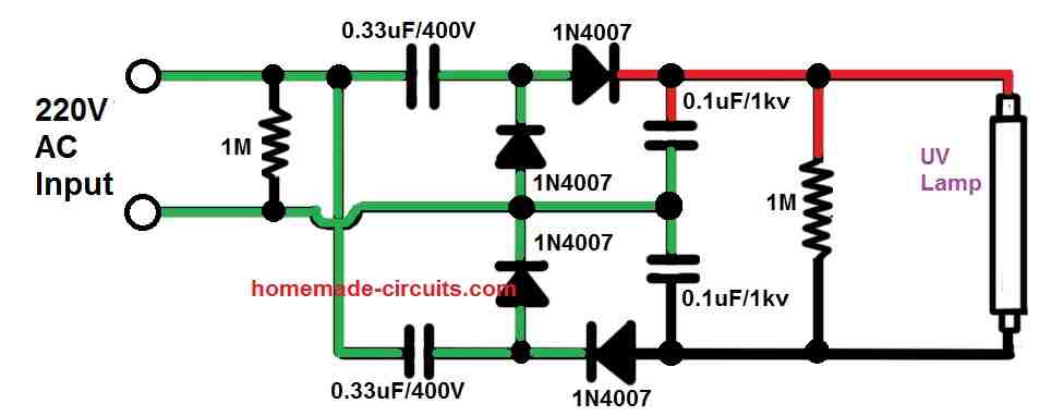
The circuit is basically a voltage doubler circuit. The horizontal 1N4007 diodes along with 0.33uF capacitors cause the input 220 V to become double at the output, across the UV lamp.
The peak voltage of 220 V RMS input is = 220 x 1.41 = 310 V.
After the voltage is doubled this 310 V turns into a massive 620 V peak to peak which is enough for driving any standard UV lamp brightly.
Warning: The circuit ideas were contributed by one of the dedicated members of this blog, the circuits are not practically verified by the author.

Questions & Answers
Hello Mr.Swagatam. Think Your for the great permanent activity in way of creation of something good.
1 – The described above cirquit “220 V UV Lamp Driver Circuit Diagram” is absolutely can not work with any lamps – both – with good and with broken filaments. I did test it in hundrids variants – lamps 18 and 36Watt and different diodes more than 400V&1Amp and different capacitors 0.01-50MicroFarads&650V and with Al-foil loop around filament’s side of tube and some other like has been recommended the “Radio” magazin at 1992-1995 years – in Russia it was hard to buy any fluorescent lamps at all for any money. The cirquit’s idea is totally can not work, maximal effect – a spark for less than 1 hour of light than MUST be changed the tube side’s polarity. Since autumn of 2005 fluorescent lamp supply has has started so good by Turque’s Osram LLC and I stop these attampts – thinks tham.
It is because of the – ALL fluorescent lamps can not work under any pulsation’s DC current, must be ONLY AC current – due to phisics of Hg-vapour’s discharge inside of tube = the Law of Nature.
2 – How many turns of transformer of the coil pin 6 to pin 3 – is it 600 turns or the L must be separately winded 600 turns but pin 6 to pin 3 just not described?
3 – The transformer is not easy to repeat – both – too expensive parts with so difficoult to wind “in hands/on a knee” with lack of appropriate winding equipment. There are 20-30 or more another cirquits with much more simple transformers design example – 2 coil only with IMC-driver or similar to a self-started multivibrator with primary simmetrical coil like pins 2-3-4 (20-50 turns each one) with one exit side coil 150-400 turns and filaments subsequently with capacitor 0.0005-0.001MicroF 650-1000V and Inductor 200-500 turns like L in the Mr. Swagatam’s article’s cirquit.
Best regards, good luck for all.
Thank you Igor, for updating the information.
The above circuits were taken from a very old magazine, it is reputed magazine.
And yes the transformer winding is critical. If there’s even a smallest of mistakes in the winding then the circuit won’t work.
However, I have tried and tested the second circuit and it works fine. I tested it with a 20 watt fluorescent tube and I could illuminate it fairly brightly.
Hello Swagatham,
I have also made a ballast circuit for Philips TUV 4W and 11W lamp. But we are facing an issue of lamp blackening. Our inverter is from 24VDC 220VAC while preheating and 80VAC while operating.
Also, we have faced that ballast circuit got stopped working after turning for some long duration for a week. I would like to take your suggestions on finetuning my transformer and inductor design. Please suggest how to connect and share the details of my circuit.
Hi Reshmi,
I understand the problem you are facing with your fluorescent tube ends darkening, which is normally caused due to overheating of the filaments. However, it can be difficult for me to troubleshoot the fault in your circuit because a fluorescent ballast has a complex ferrite transformer which requires complex calculations for getting an optimized output, and I am not well versed with the calculations involved with ballast circuits. I think a better idea would be to buy a ready-made Phillips ballast, reverse engineer it and then copy the design exactly to fulfill your requirements, or maybe someone else on this forum might be able to suggest something more useful.
Hi Swagatam,
Thanks for the quick reply.
Can you suggest some good and reliable readymade ballasts known to you?
Thanks Reshmi,
Since I have not used them practically, suggesting a reliable brand can be difficult for me. However, If you can find a Philips made unit that would be the best, although replicating a Philips model can be difficult.
I have a 30 watt UV with the usual 4 wires needed to drive the UV tube, just like the normal fluorescent tube. Do you have a 220 VAC ballast circuit for it?
You can find a few ballast circuits presented in the following page:
https://www.homemade-circuits.com/?s=ballast
hello swagatam,
i am here again. can we use Arduino to controller in this circuit. please guide
exactly i am using 24v dc.
i have visited the other sites of yours and found very informative.
still needing your guidance on the above circuit.
Thank you Ajit, Actually my knowledge of Arduino is not good, so it can be difficult for me to answer your question. I am not sure how an Arduino can be used in the above design.
thank you so much for your reply
You are welcome!
Hi thank you for your design.
Regarding the electrical wiring:
1) With what AWG cables do you connect the uvc lamps ?
2) With what material should be made the insulator of electrical wire ? I have seen PFTE or FEP are more resistant to high temperature.
Regards
You are welcome. The wire AWG is not crucial since the current through the wire is not very high. You can use any normal electrical wire which are used for LED lamps, or fluorescent lamps.
thanks
nice explanation, please mention how does the circuit work?
can it be used for 11watt or 16watt tube.
please explain.
Thank you! When one transistor is ON the other transistor is switched OFF and vice versa, in this way the whole system oscillates, producing the intended high voltage for the tube light. No it cannot be used for 11 watt or 16 watt tubes.
thank you for your reply. can you please advise the necessary changes that need to be done in order to use an 11-watt or 16-watt tube? I am a newcomer to this field. so expecting some help from you.
It is difficult to suggest a solution for your question, because that would need modifying the number of the turns of the secondary winding, which can be very complex, and will need to be done through some trial and error.
thank you for your generosity.