The circuit explained here employs a rather different approach for implementing a touch operated switch action. Here instead of the resistance, the warmth of the finger is used for sensing and operating the circuit's output.
Irrespective of the ambient conditions, our hands and fingers mostly exhibits some extra warmth or increase in the level of the temperature compared to the atmospheric levels.
Using Finger Warmth for the Triggering
This feature of our body has been exploited here for making this thermally activated touch switch circuit.
The proposed thermo-touch operated switch circuit has its own distinct advantages in contrast to the normal "touch resistance" based switches.
This design is not prone to humid areas, or wet conditions where normally a resistance based switch would falter and generate erratic results.
Using 1N4148 as the Sensor and IC 741 as the Comparator Driver
The circuit utilizes the ubiquitous 1N4148 diodes whose forward voltage drop alters by about 2 mV in response to a rise of 1 degree Celsius temperature over it.
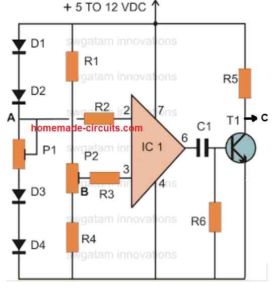
Looking at the circuit diagram, when the diodes D3 and D4 are touched with the finger, the voltage at point A drops rapidly in comparison to point B, sufficient to make the output of the IC 741 change state.
The IC 741 has been configured as a comparator, and it compares the forward voltage drop of the diodes with respect to the reference voltage clamped at point B.
The output generates a TTL or a CMOS compatible logic pulse at point C, which can be easily used for triggering a flip flop circuit and an intended load.
P1 and P2 are the presets which may used for setting and optimizing the circuits response or the sensitivity.
Parts List
- R1, R4 = 10K
- R2, R3 = 56K
- R5 = 1K
- R6 = 1M,
- P1 = 10K preset,
- P2 = 1K preset
- C1 = 104/ disc
- T1 = BC547
- IC1 = 741
- D1----D4 = 1N4148
Differential Finger Temperature Sensor Switch Circuit
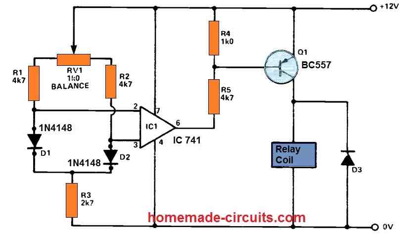
This low-cost device may serve as the foundation for a range of various home-control systems. The circuit employs a couple of standard silicon diodes as temperature sensors and a relay as an output "switch.'
The circuit action is such that the relay switches on as soon as warmth at 'A' (sensed by D1) is greater than warmth at 'B' (sensed by D2), regardless of the absolute magnitude of either temperature.
By simply inverting the sensor identities of D1 and D2, the circuit activity may be easily reversed, such that the relay switches on only when warmth at 'A' is lower than warmth at 'B'.
Ordinary silicon diodes may generate forward voltages of many 100 millivolts with current levels of one milliampere, with the actual voltage value being determined by the current value and the properties of the individual diodes employed.
Nevertheless, all silicon diodes have a nearly similar temperature coefficient of around -2mV/°C and may thus be employed as precise temperature-indicating sensors.
In the circuit, currents are allowed to pass via a couple of temperature-sensing diodes (D1 and D2) via the RV1-R1-R2-R3 network.
RV1 enables the similar specifications of the two currents to be modified over just a small range such that the diodes generate identical forward voltages once both the diodes are at the same temperature.
As a result, the differential or 'difference' voltage between the two diodes is precisely proportional to the temperature difference between them.
This difference voltage is applied to the input pins of the IC1 741, that is configured as a voltage comparator or differential voltage switch, and the output of the op-amp is applied to the relay through D1.
The operation is such that the relay activates as soon as D1's temperature exceeds that of D2. A 12 volt source is required to power the device.
When both sensor diodes (D1 and D2) are at identical warmth, RV1 is effectively changed such that the relay is turned off.
The relay can then switch on once the temperature of D1 is elevated a tiny bit over that of D2: remember, this specific behaviour may be tested at normal room temperature by just pressing D1 with finger, since body heat will provide the desired difference.
The relay connections can be used to control external devices. Any 12 volt relay having a coil resistance higher than 120 R will suffice.
This switch could be used to start a blower motor, as an example, to guarantee that a basement or underground is properly preheated by some outside airflow when the outside air temperature is increased than the cellar or basement temperature.
It may also be used to control a solenoid valve, ensuring that a storage tank is automatically replenished directly from the warmer of two water sources, and so on.
Finger Temperature Touch Switch using IC LM324
This circuit functions as a temperature-sensitive touch switch. It detects temperature changes in a diode when it comes into contact with a finger, and based on this, it can either turn an LED on or off.
Moreover, the output has the capability to activate a transistor for controlling a relay as well.
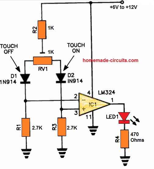
In this setup, IC1 LM324 serves as a comparator. Its non-inverting and inverting inputs are designed to monitor voltage drops across R1 and R3, respectively.
The adjustment of RV1 is critical to ensure that a slightly higher current flows through R1 compared to R3.
This configuration causes IC1's inverting input to exceed its non-inverting input, resulting in a low output signal and turning off the LED.
When you touch diode D2, the heat from your finger causes its temperature to increase. This, in turn, leads to a slight increase in its forward current, causing pin 2 to surpass pin 3.
As a result, pin 1 goes high, and the LED illuminates. Removing your finger from D2 will cause the LED to turn off.
If the ambient temperature is sufficiently high, surpassing the typical body temperature, the LED will not shut off and remain illuminated. To deactivate it in such situations, simply touch diode D1.


Questions & Answers
i want to make finger touch temperature controlling PCB circuit for appliances . can i get your contact number to meet you Personally
Sorry, due to work load it can difficult for me to accept external jobs. If you have any questions you can ask me here through comments, I will try to help.
I am interested in making this circuit for my college project, where can i get all these components, and which simulator software should i use for the same to generate output.
can you please explain how to design this circuit
circuit doesnt seem to work. the output stays on (ex. LED) is on all the time even after touching d3 and d4
you can replace D3/D4 with LM35 IC for getting confirmed results, or try the first circuit from the following article, which is a tested one:
https://www.homemade-circuits.com/2013/01/how-to-charge-25-nos-li-ion-cells-from.html