In this post I have explained 8 easy methods of building touch sensor switch circuits at home, which can be used for switching 220 V appliances ON/OFF with mere finger touch operat
ions. The first one is a simple touch sensor switch using a single IC 4017, the second one employs a Schmidt trigger IC, the 3rd one work with a flip flop based design and there's another one which uses the IC M668. I have explained the procedures in detail.
1) Using a 4017 IC for the Relay Touch Activation
Referring to the below given circuit diagram for the proposed first simple touch activated relay circuit, we can see that the entire design is built around the IC 4017 which is a 10 step johnson's decade counter divider chip.
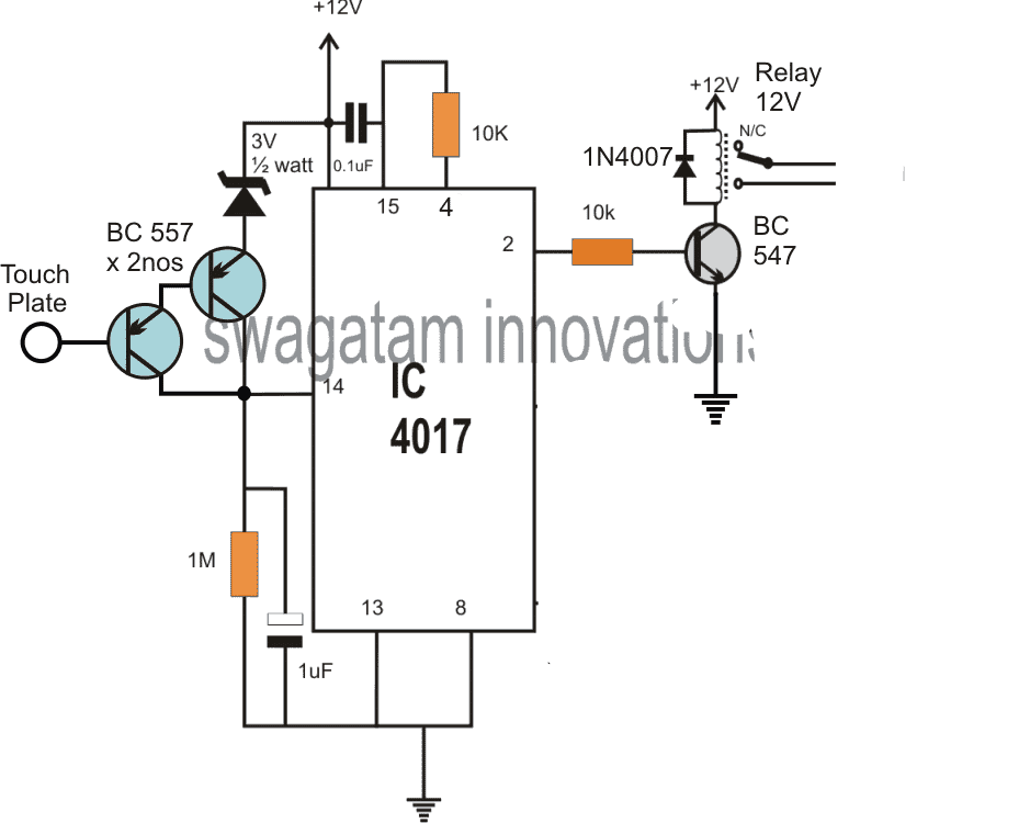
The IC basically consists of 10 outputs, starting from its pin#3 and randomly ending at pin#11, constituting 10 outputs which are designed to produce a sequencing or shifting high logics across these output pins in response to every single positive pulse applied at its pin#14.
The sequencing does not need to finish at the last pin#11, rather could be assigned to stop at any desired intermediate pinout, and revert to the first pin#3 to initiate the cycle afresh.
This is simply done by connecting the end sequence pinout with the reset pin#15 of the IC.
This makes sure that whenever the sequence reaches this pinout, the cycle stops here and reverts to pin#3 which is the initial pinout for enabling a repeat cycling of the sequence in the same order.
For example in our design pin#4 which is the third pinout in the sequence can be seen attached to pin#15 of the IC, implies that as the sequence jumps from pin#3 to the next pin#2, and then to pin#4 it instantly reverts or flips back to pin#3 to enable the cycle again.
How it Works
This cycling is induced by touching the indicated touch plate which causes a positive pulse to appear at pin#14 of the IC each time it's touched.
Let's assume at power switch ON the high logic is at pin#3, this pin is not connected anywhere and is unused, while pin#2 can be seen connected with the relay driver stage, therefore at this moment the relay stays switched OFF.
As soon as the touch plate is tapped, the positive pulse at pin#14 of the IC toggles the output sequence which now jumps from pin#3 to pin#2 enabling the relay to switch ON.
The position is held fixed at this point, with the relay in the switched ON position and the connected load activated.
However as soon as the touch plate is touched again, the sequence is forced to jump from pin#2 to pin#4, which in turn prompts the IC to revert the logic back to pin#3, switching OFF the relay and the load and enabling the IC back to its standby condition.
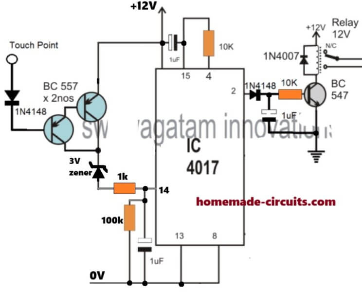
Improved Modified Design
The above touch operated flip flop bistable circuit might show some oscillation in response to finger contact, leading to relay chattering.
To eliminate this issue, the circuit should be modified as given in the following diagram.
Or you may also follow the diagram which is shown in the video.
2) Touch Sensitive Switch Circuit Using IC 4093
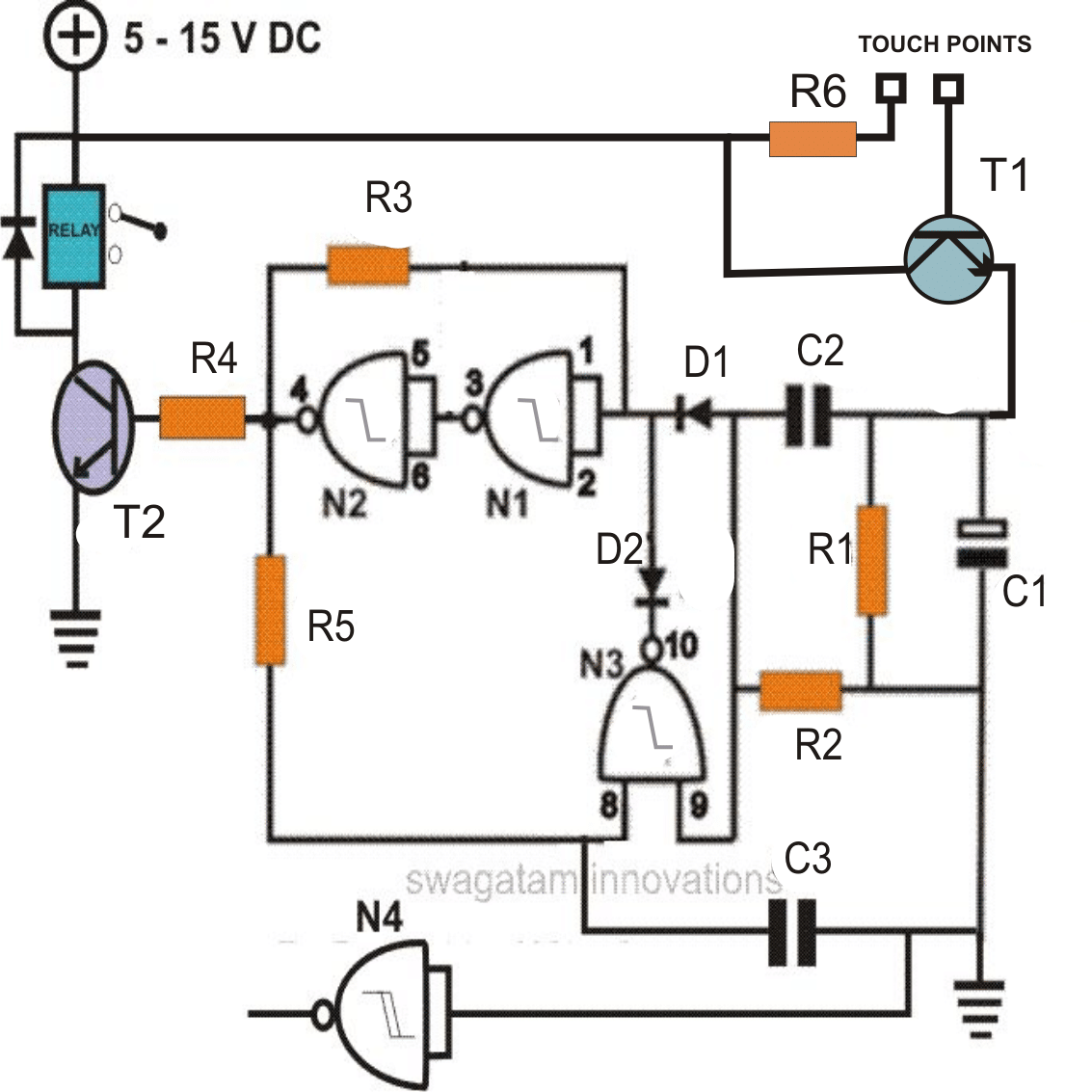
This second design is another accurate touch sensitive switch can be built using a single IC 4093 and a few other passive components.
The shown circuit is extremely accurate and fail-proof.
The circuit is basically a flip-flop that may be triggered through manual finger touches.
Using Schmitt Trigger
The IC 4093 is a Quad 2-input NAND Gate with Schmidt trigger. Here we employ all the four gates from the IC for the proposed purpose.
How the Circuit works
Looking at the figure the circuit may be understood with the following points:
All the gates from the IC are basically configured as inverters and any input logic is transformed into an opposite signal logic at the respective outputs.
The first two gates N1 and N2 are arranged in the form of a latch, the resistor R1 looping from the output of N2 to the input of N1 becomes responsible for the desired latching action.
Transistor T1 is Darlington high gain transistor which has been incorporated for amplifying the minute signals from the finger touches.
Initially when power is switched ON due to the capacitor C1 at the input of N1, the logic at the input of N1 is pulled to ground potential making N1 and N2 feedback system latch with this input producing a negative logic at the output of N2.
The output relay driver stage is thus rendered inactive during initial power switch ON.
Now suppose a finger touch is made at the base of T1, the transistor instantly conducts, driving a high logic at the input of N1 via C2, D2.
C2 charges instantly and blocks any further faulty triggers from the touch, making sure the de-bouncing effect does not disturb the operation.
The above logic high instantly flips the condition of N1/N2 which now latches to produce a positive at the output, triggering the relay drive stage and the corresponding load.
So far the operation looks pretty straightforward, however now the next finger touch should make the circuit collapse and return to its original position and for implementing this feature, N4 is employed and its role becomes truly interesting.
After the above triggering is done, C3 gradually gets charged (within seconds), bringing a logic low at the corresponding input of N3, also the other input of N3 is already held at logic low through the resistor R2, which is clamped to ground.
N3 now becomes stationed in a perfect stand by position “waiting” for the next touch trigger at the input.
Now suppose the next subsequent finger touch is made at the input of T1, another positive trigger is released at the input of N1 via C2, however it does not produce any influence over N1 and N2 as they are already latched in response with the earlier input positive trigger.
Now, the second input of N3 which is also connected to receive the input trigger via C2 instantly gets a positive pulse at the connected input.
At this instant both the inputs of N3 goes high. This generates a logic low level at the output of N3.
This logic low immediately pulls the input of N1 to ground via the diode D2, breaking the latch position of N1 and N2.
This causes the output of N2 to become low, switching OFF the relay driver and the corresponding load. We are back into the original condition and circuit now waits for the next subsequent touch trigger in order to repeat the cycle.
Parts List
Parts required for making a simple touch sensitive ON/OFF switch circuit.
- R1, R2 = 100K,
- R6 = 1K
- R3, R5 = 2M2,
- R4 = 10K,
- C1 = 100uF/25V
- C2, C3 = 0.22uF
- D1, D2, D3 = 1N4148,
- N1---N4 = IC 4093,
- T1 = 8050,
- T2 = BC547
- Relay = 12 volts, SPDT
The above design can be further simplified using just a couple of NAND gates, and a relay ON OFF circuit. The entire design can be witnessed in the following diagram:
3) 220V Electronic Touch Switch Circuit
It may be now possible to convert your existing mains 220V light switch circuit with the electronic touch switch circuit explained in this 3rd configuration.
This third idea is built around the chip M668 and it employs just a handful of other components for implementing the proposed mains touch switch ON/OFF application.
How this simple mains electronic touch switch circuit works
The indicated 4 diodes form the basic bridge diode network, the thyristor is used for switching the mains 220V AC for the load, while the IC M668 is used for processing the ON/OFF latching actions whenever the touch switch is touched.
The bridge network rectifies the AC into DC through R1 which limits the AC current to safe level for the circuit, and VD5 regulates the DC suitably.
The final outcome is a rectified, stabilized 6V DC which is applied to the touch circuit for the operations.
The touch plate is connected with a current limiting network using R7/R8 so that no shock sensation is felt by the user while putting finger on this touch pad.
The various pinout functions of the IC can be learned from the following points:
The supply positive is applied to pin#8 and ground to pin#1 (negative) The touch signal on the touch pad is sent to pin#2, and the logic is transformed into an ON or OFF at the output pin#7.
This signal from pin#7 subsequently drives the SCR and the connected load into either ON or OFF states.
C3 makes sure that the SCR is not false triggered due to multiple pulses in response to an improper or inadequate touching on the touch pad. R4 and C2 forms an oscillator stage for enabling the required processing of the signals within the IC.
A synchronization signal from R2/R5 is divided internal through pin#5 of the IC. Pin#4 of the IC has a very crucial and interesting function.
When connected with the positive line or Vcc, the IC enables the output to alternately toggle ON/OFF, allowing the light or the load to switch ON and OFF alternately in response to every touch on the touch pad.
However when pin#4 is connected to the ground or the negative line Vss, it transforms the IC into a 4 stage dimmer circuit.
Meaning in this position every touch on the touch pad causes the load ( a lamp for example) to reduce or increase its intensity sequentially, in a gradually dimming or gradually brightening manner ( and OFF at the ends).
If you have any questions regarding the functioning of the above discussed mains touch switch circuit please write them down through the comment box...
4) Touch Activated Lamp Circuit with Delay Timer
The fourth design is a transformerless touch activated 220V delay lamp switch circuit enables the user to momentarily switch ON a table lamp or any other desired bed lamp during night time.
How the circuit Works.
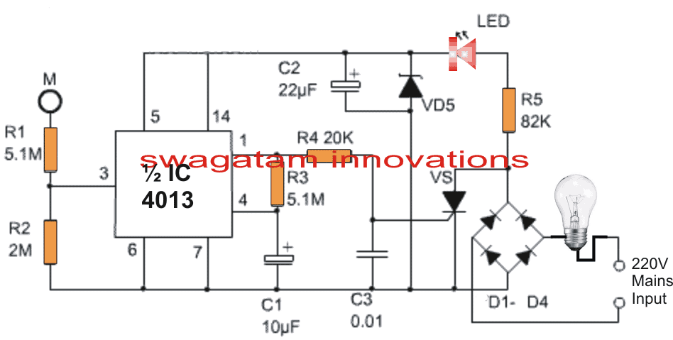
Referring to the circuit above, the four diodes at the input form the basic bridge rectifier circuit for rectifying the mains AC into DC.
This rectified DC is stabilized by the 12V zener and filtered by C2 to acquire a fairly clean DC for the accompanying touch switch circuit.
R5 is used for limiting the input mains current to a much lower level suitable for operating the circuit safely.
An LED can be seen connected with this supply which ensures a dim light is always ON near the circuit for facilitating quick location of the touch switch pad.
The IC used in this transformers touch lamp with delay circuit is a double D flip-flip IC 4013, which has 2 flip flop stages built inside it, here we make use of one of these stages for our application.
Whenever the indicated touch pad is touched by finger, our body offers a leakage current on the point causing a momentary high logic on pin#3 of the IC, which in turn causes the pin#1 of the IC to go high.
When this happen the attached triac is triggered via R4, and the bridge rectifier completes its cycle powering the series lamp. The lamp now illuminates brightly.
Also in the meantime, the capacitor C1 gradually starts charging via R3, and when it gets fully charged pin#4 is rendered with a high logic which resets the flip flop in its original condition.
This instantly turns pin#1 low switching OFF the SCR and the lamp.
The value of the R3/C1 produces a delay of about 1 minute, this can be increased or decreased by suitably increasing or decreasing the values of these two RC components as per individual preference.
5) Touch Sensor Switch using a Single MOSFET
Just a single MOSFET and few additional passive parts are all that's needed to build this 5th touch sensor circuit.
The MOSFET gate can be seen connected with a 22M resistor, and a touch sensor built using a PCB with copper mesh on it.
With the indicated 22 M resistor, even breathing on the sensor mesh will be enough for the MOSFET to turn OFF momentarily.
If you find this sensitivity to high, you can reduce the 22M to 10M then it will allow the MOSFET to turn OFF with a finger touch on the copper sensor board.
During the absence of a touch on the sensor, the MOSFET remains in the switched ON condition, due to the positive voltage arriving from R1.
During this period the base voltage to Q2 via R2 remains grounded through the MOSFET drain which causes the Q2 transistor to remain switched OFF. With Q2 switched OFF, the relay also remains switched OFF.
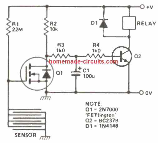
As soon as the sensor plate is touched, it instantly causes a grounding of the R1 voltage through the finger, forcing the MOSFET to turn OFF.
When the MOSFET is turned OFF, the Q2 transistor gets the access to the potential from the R2, and it turns ON now, When Q2 turns ON, the relay coil gets the required amount of power, and it also turns ON, switching ON any load that may have been configured across its contacts.
Removing the finger from the touch sensor, restores the circuit to its original form, and the relay switches OFF.
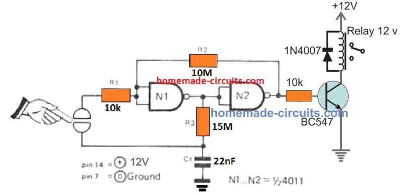
6) Using IC 4011
Working with just one 1 / 2 of an IC 4011, along with a few general purpose BJTs, this 7th touch operated switch could be designed which can be well suited for numerous battery powered circuits.
Considering that all the inputs to the leftover gates of the IC 4011 are connected to the ground line, the current consumed by the IC in the off state is practically zero which means the battery life will be long and unaffected.
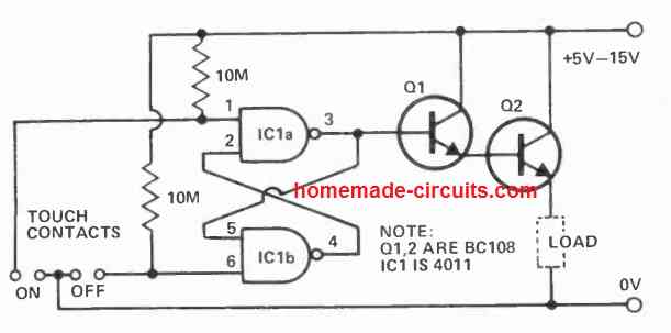
When the 'on' contacts are touched with a finger causes pin 3 to become high, which turns on the darlington pair and power is supplied to the load.
When the 'off' contacts are touched, the opposite happens, and the action switches OFF the load.
Q1 needs to be a high gain transistor, and Q2 picked out according to the current specifications of the load.
7) Using IC 4001 and IC 4020
In this 8th touch switch sensor idea, when the input contact of gate 1 (which, as the other three gates in the device, is linked to function as an inverter) is touched, stray mains hum is picked up and connected to the input of gate 1 (which, just like the other three gates in the device, is wired to function as an inverter) through R1.
The input signal is able to of switching gate 1 input from one logic level to the other since IC1 is a CMOS device with a very high input impedance.
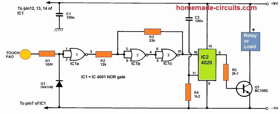
Because the IC 4001 circuit's input impedance is so large, the backward resistance of D1 is utilized to connect the input to ground during idle situations, preventing erroneous activity.
In combination with the circuit's input capacitance, R1 works as a low pass filter, attenuating noise and interference that may be encountered on the 50Hz mains signal.
The output from gate 1 still has substantial amount of noise components and a rise time that is insufficient to operate the circuit's end stage.
The trigger circuit built around gates 2 and 3 is used to resolve this issue.
Due to the connection with R2, R3 tries to keep gate 2 input in almost the same condition as gate 3 output, preventing any change in logic state induced by gate 1 output.
Because R2 is smaller than R3, gate 1 can drive the trigger circuit if its output signal is large enough.
The main 50Hz signal will be powerful indeed, however the noise spikes may not, and therefore will be removed from the trigger's output.
The connection across R3 guarantees a fast shift whenever the trigger's output begins changing state.
IC2 is a 14-stage binary (division by 2) counter, and Q1 is operated from the output of the seventh stage via current limit resistor R5.
At power up, C2 and R4 send a positive reset pulse to the counter, causing the outputs to be low and Q1 to be turned off.
The load for transistor Q1 is formed by the regulated device, which apparently gets no substantial power.
A 50Hz signal is provided to IC2 when the touch contact is activated, and the 7th stage output swaps state after 64 pulses.
The load is turned on and off as this output swings high and low. In practice, the contact is held just long enough for the unit to transition to the ideal state (which the user wants to do automatically).
In the "off" position, the unit uses around 1uA, while in the "on" position, it draws roughly 3mA.
Using IC 4093
Presenting an innovative touch-sensitive switch configuration with broad applicability that relies solely on easily available components.
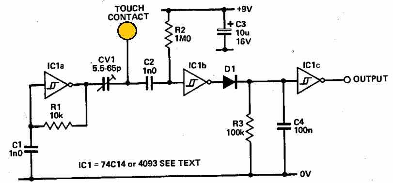
In its fundamental configuration, the output state rests at logic 0. Upon contact, an ingenious mechanism swiftly transforms the output to logic 1.
The core of the setup features IC1a operating within an oscillator arrangement generating an approximate 200 kHz frequency.
Throughout the periods when the contact remains untouched, a high-frequency signal of this oscillator circulates through CV1 and C2 before reaching the input of IC1b.
This Schmitt inverter synchronizes with the signal frequency, upholding the charge across C4.
However, when the touch plate encounters a finger touch, the signal transmitted to IC1b's input undergoes significant attenuation due to the combined influence of CV1's potential division and the finger's capacitance.
Consequently, IC1b's output ceases its oscillation, stabilizing at logic 0. Following this, C4 undergoes discharge via R3, leading IC1c's output to transition to logic 1.
To fine-tune sensitivity, optimal adjustments should be made to CV1.
Depending on the specific requirements, slight deviations in the value of C1 might be necessary due to the tolerances of the 74C14's Schmitt triggers.
The estimated operational frequency can be roughly calculated using the equation f = 2 / (R1 x C1).
Inclusion of C2 serves the purpose of suppressing potential hum-induced interference that might otherwise trigger IC1b erroneously.
As an alternative, one can opt for utilizing IC 4093 gates configured as inverters instead of the 74C14s for those who prefer that option.
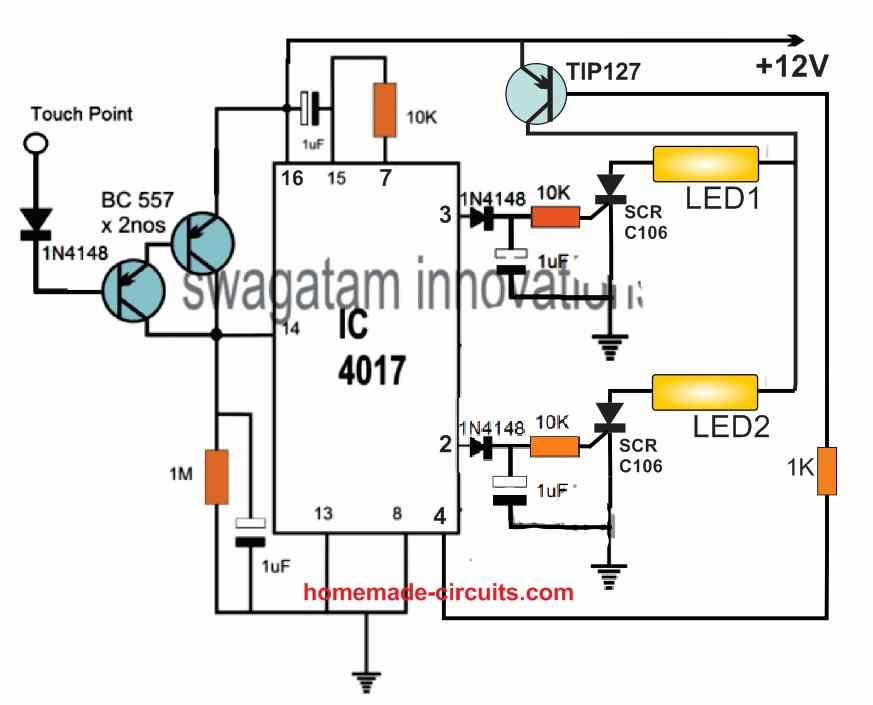
Touch Controlled Sequential LED Lamp Circuit
The following touch controlled sequential LED lamp will work in the following manner:
When power is switched ON, a short pulse is sent to pin#15 through the connected 1uF capacitor. The short positive pulse resets the IC such that a logic high is reached at pin#3.
With a logic high at pin#3 the connected SCR is switched ON and LED1 is also switched ON. Since the supply is DC, the SCR latches the LED1 permanently ON, and keeps it ON permanently.
After this, if the touch pad is touched once, the high logic at pin#3 jumps to pin#2.
The SCR on pin#2 similarly latches and switches ON LED2 permanently. Therefore now, both LED1 and LED2 are switched ON one after the other.
Next, if the touch pad is touched again, the logic high from pin#2 jumps to pin#4, which causes the TIP127 transistor to get a high logic at its base, so that it turns OFF.
When the TIP127 transistor is turned OFF, the DC supply to the LEDs is also turned OFF, which breaks the latching of the two SCRs. Both the SCRs now switch OFF and the LEDs also switch OFF.
At this position if the touch pad is touched yet again, causes the logic high at pin#4 to jump to the next output pin which is pin#7.
However, since pin#7 is connected to pin#15 of the IC this logic high resets the IC back. The resetting action causes the logic high to go back to pin#3, causing the relevant SCR to switch ON (latch)and the LED1 to illuminate. The process now repeats.
As we can see only two LEDs are used here, however since there are 10 outputs for the IC 4017, we can use a total number of 10 LEDs in this circuit.
The pinout sequence of the IC are in the order: 3, 2, 4, 7, 10, 1, 5, 6, 9, 11
As you will notice, in our circuit the first 4 sequencing pinout are used which 3, 2, 4, 7. Pin#4 is used to switch OFF the transistor and the SCRs, pin#7 is used to reset the IC back to pin#3.
It means, the two pinouts which comes immediately after the last LED in the sequence can be used for turning of the transistor and the resetting the IC respectively.
Let's say, we want to use 8 sequentially activating LEDs. For this we have to use the pinouts 3, 2, 4, 7, 10, 1, 5, 6 for connecting the SCR/LED networks.
In this situation, the two subsequent pinouts which comes after the pin#6 (which is the last LED pinout) can be used for turning off the transistor and for resetting the IC. These two pinouts are obviously pin#9 and pin#11.
This is how you can configure the pinouts of the IC 4017 for getting the desired number LEDs to illuminate sequentially, through touch activation.


Questions & Answers
Hello Swagatam,
I have a lamp with a four stage touch dimmer. Each touch cycles through LOW – MED – HIGH – OFF. It is a very nice lamp, but has two disadvantages:
1. it’s dimmer does not cope well with modern LED based Light bulbs. So traditional bulbs with higher watts are required to avoid flickering.
2. it can’t be controlled remotely with RF switches or the like, as it starts in the OFF – position, when disconnected and reconnected from mains voltage.
Therefore I would like to replace the original circuit board with the following dimmer:
And I would also like to maintain the local touch functionality for ON/OFF and dimming.
This has an input for a momentary switch – short impulses switch ON or OFF and closing the switch for a longer time does the dimming.
The switch does not have to carry much load, but is fed by the live mains-signal.
So I am looking for a ciruit like No. 3 or 4 but without the need to hold the state and no need to handle much load, as it’s just a signal line. So probably something even simpler than the two circuits.
Which modifications are necessary? could/should it be done emploing a TTP223?
Or would You take a completely different path?
Thanks for Your support
Kind regards
Frank
Hi Frank,
Thanks for your question, I will try to figure out the design and let you know soon, if it is possible for me…
Hi Swagatam,
Can you provide a reliable momentary single pad touch circuit with relay that i can power with 5v DC. Touch sensor pad with finger relay turns on instantly, take finger off pad relay turns off instantly.
Hi Lawrie,
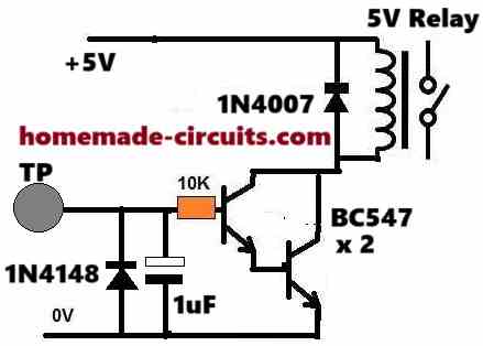
Please test the following circuit and see if it works or not:
Thank you for the circuit. It seems to work fine except the relay chatters when i touch TP with my finger. If I put 5v on at TP the relay works perfectly. Note – I don’t have a lot of options for components so am using a 50pF capacitor. I don’t have a 1N4148 so using the circuit without this Diode at the moment. Could that be causing my problem?
Yes, the chattering is happening because of not including the 1uF capacitor and the 1N4148 diode. Please try including them and let me know how it goes….
I have now included the 1N4148 diode and the 1uF polarised cap. When I touch TP I get no response from the reed relay.
OK, then please remove both of these components and connect a 4.7uF or 10uF capacitor directly across the relay coil, and check the response.
With the 4.7uF across the coil the relay still chattered and the TP became highly sensitive and would turn the relay on as my finger got close to it without actually touching TP. With the 10uF across the coil it still chattered but only activated when I touched TP.
With no other diodes or caps other than the flyback diode across the coil and the 10k resistor on the base of the first Transistor i place a 10uF cap on the emitter to base junction to ground.This now seems to work very well without any chatter in the relay. I don’t know if this is the right way to go about it but it works.
Also if i connect TP directly to the base of transistor 1 without the resistor it also works fine. Is it better to have the resistor on the base before the TP?? Your thoughts on the above will be appreciated.
Yes, adding a capacitor across base/emitter or base/ground is the recommended method, but I did not suggest it because you wanted the response to be instant. Adding a base/emitter capacitor would cause a slight delay in the relay operation. However if you are satisfied with the results then it is fine, you can use it. You can also try reducing the base/emitter capacitor value to 1uF so that the chattering also stops and the delay is negligible.
I would recommend having some resistance between the base and the TP instead of a direct connection… maybe a 100 ohm would be fine.
OK yes I have been playing with the base to ground capacitance and I’m satisfied so far with the amount of delay, which is not really noticeable and changed the resistor to 100ohm. I will test over the next few days to see how it performs. Many thanks for your help, it’s very much appreciated .
Sure, no problem! Let me know if you have any further issues with the circuit…
Good afternoon my good friend Swagatam.Perhaps you know a circuit with which I could sequentially press the touch sensor and turn on this or that load.
For example, I have 4 rows(10 pieces) of 5050 smd LEDs. The task is to turn on one row with one touch, turn on the second row with the second touch, and so on, and turn it all off with the last touch.
Thank you in advance for your hint.
Thank you Jorge,
I will surely try to figure out the circuit and will update it soon in the above article!
please can I use this circuit to switch on and off an induction motor using the reply?
You can do it, if you replace the SCRs with triacs. However, if the supply is AC then the induction motors will not latch and remain ON, they will switch ON/OFF alternately…
Waiting for your help!
Thank you for waiting friend! Please see the following example design, I have shown two LED stages, but you increase it up to 10 LED stages. Note the connection of pin#4 and pin#7, you will have to change these pinout numbers depending on how many LED stages you use.
Thank you, my friend!!!
But I need the explain of this circuit. How I can connect 4-6 stages of LED? How I need to change pin 4 and pin 7 for 5-6 stages? What type of LEDs you use in your circuit? I have smd5050 LED’s, is it sute?
My stupidity…Sorry…
No problem at all, I have explained the circuit at the bottom of the above article. You can check it out.
Yes you can use 5050 LEDs since they are 12 V modules.
Thank you, my friend! I’ll try to assemble this circuit, then send you report about it! It’s very useful for my aquarium illumination.
You are welcome my friend! let me know if you have any problems or doubts.
Thanks for your amazing work. Am designing a touch activated security alert system(cell phone speed dial, 4second on then off). Which of these do you suggest I use?
Hi, thanks! You can try the second design which is a tested one.
Hello, Swatagam ,
My problem is, when I use a long wire for the touch pad , the circuit becomes very sensitive et sometimes, it triggers without touching the touch pad . I mean I used a long wire between touch pad and the circuit. For example, the touch pad is connected to the door and the circuit itself is far away What to do in this case?
With many thanks.
Hello Mohamad, yes long wire will cause problems since it will work like an antenna and catch the unwanted hum signal from the atmosphere, so it is not recommended.
However, you an try adding a 0.22uF capacitor between the base of the BC557 and the positive 12V line and check the response! Hope it solves the issue.
Thanks very much for this prompt response
Greedings from Algeria
Thank you, I am glad to help!
i am trying to 3 circuit but IC is not available in market chennai then c3 and zener diode value and voltage not mentioned so please send me clear and details circuit diagram
If IC is not available to you, then you cannot build the circuit..
Touch Switch light Circuits
Thanks for your efforts in providing the touch activated switch. May I know why the 4th circuit is not published, or does one need to pay before getting the circuit diagram ?
4rth circuit is posted and clearly visible to me….please refreshing your page or try from some other browser…
Thanks for the urgency in reply. I actually used another browser (chrome) and I found the circuit.
My question now is that I will like to modify the circuit such that it will only operate on DC. If that be the case, I know the bridge rectifier, the 82k resistor and may be the 12v zener diode will be omitted…WHERE WILL I CONNECT THE ANODE OF THE SCR??
You are welcome! May I know the reason behind using an external DC, because with an SCR your circuit will not be isolated from mains anyway?
By the way you will need a triac instead of an SCR if you prefer to power the circuit from an external DC, and it won’t be isolated from mains
On 2nd circuit,
Left of pin 15,
Which connects to +12v.
Is it pin 16?
yes it is pin16
thx… works fine
Hello.
I built second circuit touch switch.(the one 1n4148 attached to touch plate).
Are the components correct and as it shows in the diagram?
Sadly not working…
Dear Sir,
I have mounted the touch circuit on a PCB and it works great. When I connected the touch pin to my main metal gate, it stays on.
I asked an electronics technician for advice, they told me the circuit was picking up all the signal around.
Can you please help me, how to mitigate all unwanted signals?
Cordially
Dear Henri, that is correct, the touch pate cannot be a large metallic object, otherwise it may pick up stray signals and causes problems. You can try putting a 0.22uF capacitor across the base and the positive supply line of the BC557 Darlington input transistors and see if that prevents the stray pick up
I have a weird question. I’m pretty novice when it comes to this stuff, so sorry in advance. I would like to make a momentary capacitive circuit that runs off a small wafer/watch battery, that turns on a surface mounted LED. But, instead of having one touch point that turns on the LED, I want several points touched at the same time, to complete the circuit. And, if only one point is touched, it would not turn on. Would this be possible? Thanks in advance for your help!
yes that seems possible by using multiple SCRs connected via separate diodes at the pin14 of the IC 4017, and SCR gates configured with separate touch switches